Vega VEGAFLEX 82 Quick Setup Manual
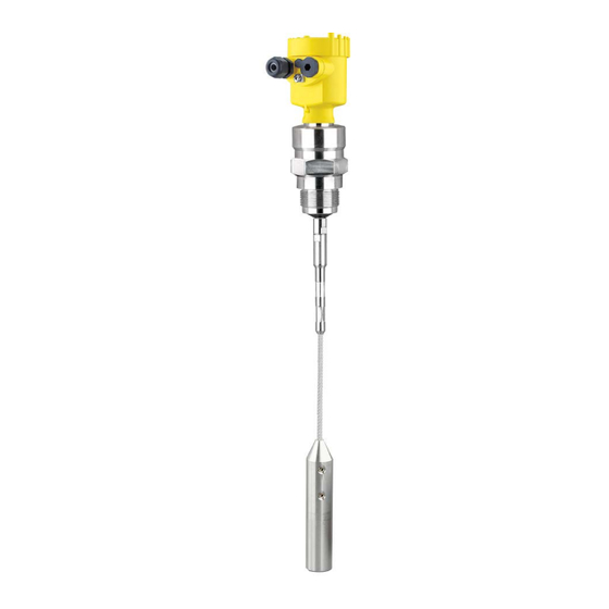
Tdr sensor for continuous level measurement of bulk solids
Hide thumbs
Also See for VEGAFLEX 82:
- Operating instructions manual (96 pages) ,
- Quick setup manual (20 pages) ,
- Supplementary instructions manual (24 pages)

Related Manuals for Vega VEGAFLEX 82


Summary of Contents for Vega VEGAFLEX 82
- Page 1 Quick setup guide TDR sensor for continuous level measurement of bulk solids VEGAFLEX 82 Two-wire 4 … 20 mA/HART SIL Rod and cable probe With SIL qualification Document ID: 47597...
-
Page 2: Table Of Contents
Operating Instructions Manual as well as the Safety Manual that comes with instruments with SIL qualification. These manuals are available on our homepage. Operating instructions VEGAFLEX 82 - Two-wire 4 … 20 mA/ HART - Rod and cable probe - With SIL qualifikation: Document- ID 44222 Editing status of the quick setup guide: 2023-05-23... -
Page 3: For Your Safety
During work on and with the device, the required personal protective equipment must always be worn. Appropriate use VEGAFLEX 82 is a sensor for continuous level measurement. You can find detailed information about the area of application in chapter " Product description". Operational reliability is ensured only if the instrument is properly used according to the specifications in the operating instructions manual as well as possible supplementary instructions. -
Page 4: Sil Qualification According To Iec 61508
DIN EN ISO 14001. Please help us fulfil this obligation by observing the environmental instructions in this manual: • Chapter " Packaging, transport and storage" • Chapter " Disposal" VEGAFLEX 82 • Two-wire 4 … 20 mA/HART SIL... -
Page 5: Product Description
Alternatively, you can access the data via your smartphone: • Download the VEGA Tools app from the " Apple App Store" or the " Google Play Store" VEGAFLEX 82 • Two-wire 4 … 20 mA/HART SIL... - Page 6 2 Product description • Scan the QR-code on the type label of the device or • Enter the serial number manually in the app VEGAFLEX 82 • Two-wire 4 … 20 mA/HART SIL...
-
Page 7: Mounting
" Technical data" of the operating instructions. Fig. 2: Vessel with conical bottom Type of vessel Plastic vessel/Glass vessel The guided microwave principle requires a metallic surface on the process fitting. Therefore, in plastic vessels, etc., use an instru- VEGAFLEX 82 • Two-wire 4 … 20 mA/HART SIL... - Page 8 Fig. 3: Mounting in non-metallic vessel Flange Metal sheet Concrete vessel When mounting in thick concrete ceilings, VEGAFLEX 82 should be mounted front flush to the lower edge. In concrete silos, the distance to the wall should be at least 500 mm (20 in). VEGAFLEX 82 • Two-wire 4 … 20 mA/HART SIL...
- Page 9 In such cases, always carry out a false signal suppression after mounting. You can find further information under " Setup procedure". DN25 ... DN150 ≤ 150 mm (5.91") ≤ 100 mm (3.94") > DN150 ... DN200 Fig. 5: Mounting socket When welding the nozzle, make sure that the nozzle is flush with the vessel top. VEGAFLEX 82 • Two-wire 4 … 20 mA/HART SIL...
- Page 10 3 Mounting Fig. 6: Nozzle must be installed flush Unfavourable mounting 2 Nozzle flush - optimum mounting VEGAFLEX 82 • Two-wire 4 … 20 mA/HART SIL...
-
Page 11: Connecting To Power Supply
7. Check the hold of the wires in the terminals by lightly pulling on them 8. Connect the shielding to the internal ground terminal, connect the external ground terminal to potential equalisation VEGAFLEX 82 • Two-wire 4 … 20 mA/HART SIL... -
Page 12: Wiring Plan, Single Chamber Housing
Display 6 7 8 Fig. 9: Connection compartment - double chamber housing Voltage supply, signal output For display and adjustment module or interface adapter For external display and adjustment unit Ground terminal for connection of the cable screening VEGAFLEX 82 • Two-wire 4 … 20 mA/HART SIL... -
Page 13: Set Up With The Display And Adjustment Module
The display and adjustment module is powered by the sensor, an ad- ditional connection is not necessary. Fig. 10: Installing the display and adjustment module in the electronics compart- ment of the single chamber housing VEGAFLEX 82 • Two-wire 4 … 20 mA/HART SIL... -
Page 14: Parameter Adjustment
- e.g. in a horizontal cylindrical or spherical tank. Activate the appropriate curve. Parameterization example The sensor measures the distance from the sensor (reference plane) to the product surface. VEGAFLEX 82 • Two-wire 4 … 20 mA/HART SIL... - Page 15 1. In the menu " Additional settings", menu item " Damping" you can adjust the requested damping of the output signal. 2. Select the parameter of the current output and the output charac- teristics in the menu item " Current output". VEGAFLEX 82 • Two-wire 4 … 20 mA/HART SIL...
-
Page 16: Setup With Smartphone/Tablet (Bluetooth)
The menu item " PIN" is only displayed if in the menu " Setup", " Lock/ Unlock adjustment" the adjustment is released. 2. Change sensor PIN Note: Bluetooth access can only be established if the current sensor PIN differs from the default setting " 0000". It is possible both when the VEGAFLEX 82 • Two-wire 4 … 20 mA/HART SIL... -
Page 17: Connecting
Bluetooth-capable instru- ments in the area. PC/Notebook Start PACTware and the VEGA project assistant. Select the device search via Bluetooth and start the search function. The device auto- matically searches for Bluetooth-capable devices in the vicinity. -
Page 18: Supplement
Ʋ for 9.6 V < U < 14 V ≤ 0.7 V (16 … 400 Hz) Ʋ for 18 V < U < 36 V ≤ 1 V (16 … 400 Hz) Load resistor Ʋ Calculation )/0.022 A Ʋ Example - with U = 24 V DC (24 V - 9.6 V)/0.022 A = 655 Ω VEGAFLEX 82 • Two-wire 4 … 20 mA/HART SIL... - Page 19 Notes VEGAFLEX 82 • Two-wire 4 … 20 mA/HART SIL...
- Page 20 Subject to change without prior notice © VEGA Grieshaber KG, Schiltach/Germany 2023 VEGA Grieshaber KG Am Hohenstein 113 Phone +49 7836 50-0 77761 Schiltach E-mail: info.de@vega.com...
Need help?
Do you have a question about the VEGAFLEX 82 and is the answer not in the manual?
Questions and answers