Table of Contents
Advertisement
Quick Links
AN2018-32 EVAL-M1-CTE620N3 User Manual
EVAL-M1-CTE620N3 User Manual
iMOTION™ Modular Application Design Kit
About this document
Scope and purpose
This user manual provides an overview of the evaluation board EVAL-M1-CTE620N3 including its main features,
key data, pin assignments and mechanical dimensions.
EVAL-M1-CTE620N3 is an evaluation board as part of the iMOTION™ Modular Application Design Kit. This power
board including a 3-phase CIPOS™ Tiny Intelligent Power Module (IPM) for motor drive application. In
combination with the control board equipped with the M1 20pin interface connector such as EVAL-M1-101T, it
features and demonstrates Infineon's CIPOS™ Tiny IPM technology and Advanced Motion Control Engine (MCE
2.0) technology for permanent magnet motors drive over the full speed range.
This evaluation board EVAL-M1-CTE620N3 was developed to support customers during their first steps
designing applications with CIPOS™ Tiny IPM and running any permanent magnet motor via sensorless
sinusoidal control.
Intended audience
This user manual is intended for all technical specialists who know motor control and high power electronics
converter and this board is intended to be used under laboratory conditions.
Table of contents
About this document ....................................................................................................................... 1
Table of contents ............................................................................................................................ 1
1
Safety precautions ................................................................................................................. 3
2
Introduction .......................................................................................................................... 4
3
EVAL-M1-CTE620N3 main features............................................................................................ 6
3.1
EVAL-M1-CTE620N3 board specifications .............................................................................................. 7
3.2
Pin assignment ........................................................................................................................................ 9
4
Getting Started with EVAL-M1-CTE620N3 ................................................................................. 11
4.1
Setting up the system............................................................................................................................ 11
4.2
iMOTION™ development tools and software ....................................................................................... 13
4.2.1
MCEWizard setup overview .............................................................................................................. 13
4.2.2
MCEDesigner setup overview .......................................................................................................... 15
5
Hardware description of EVAL-M1-CTE620N3 ........................................................................... 17
5.1
Inverter section using CIPOS™ Tiny IPM ............................................................................................... 17
5.1.1
DC bus sensing and MCEWizard configuration ............................................................................... 18
5.1.2
Motor External Current feedback configuration and calculation .................................................. 19
5.1.3
Inverter Overcurrent protection and Motor Gatekill configuration ............................................... 21
5.2
Thermistor/NTC Characteristics and protection calculation .............................................................. 22
5.2.1
CIPOS™ Internal NTC - Thermistor Characteristics ........................................................................ 22
5.2.2
Overtemperature Hardware Protection Circuit .............................................................................. 23
5.2.3
NTC shutdown value calculation and configuration ...................................................................... 24
5.3
Auxiliary power supply .......................................................................................................................... 25
User Manual
Please read the Important Notice and Warnings at the end of this document
Revision 1.0
2018-08-23
Advertisement
Table of Contents

Related Manuals for Infineon EVAL-M1-CTE620N3


Summary of Contents for Infineon EVAL-M1-CTE620N3
-
Page 1: Table Of Contents
This user manual provides an overview of the evaluation board EVAL-M1-CTE620N3 including its main features, key data, pin assignments and mechanical dimensions. EVAL-M1-CTE620N3 is an evaluation board as part of the iMOTION™ Modular Application Design Kit. This power board including a 3-phase CIPOS™ Tiny Intelligent Power Module (IPM) for motor drive application. In combination with the control board equipped with the M1 20pin interface connector such as EVAL-M1-101T, it features and demonstrates Infineon’s CIPOS™... - Page 2 EVAL-M1-CTE620N3 User Manual iMOTION™ Modular Application Design Kit Table of contents Schematics for EVAL-M1-CTE620N3 ..................... 26 PCB Layout for EVAL-M1-CTE620N3 ..................... 28 Reference ..........................35 Revision history..........................36 User Manual 2 of 37 Revision 1.0 2018-08-23...
-
Page 3: Safety Precautions
Table 1 Precautions Attention: The ground potential of the EVAL-M1-CTE620N3 system is biased to a negative DC bus voltage potential. When measuring voltage waveform by oscilloscope, the scope’s ground needs to be isolated. Failure to do so may result in personal injury or death and equipment damage. -
Page 4: Introduction
The EVAL-M1-CTE620N3 evaluation board is available through regular Infineon distribution partners as well as on Infineon's website. The features of this board are described in the main features chapter of this document, whereas the remaining paragraphs provide information to enable the customers to copy, modify and qualify the design for production according to their own specific requirements. - Page 5 EVAL-M1-CTE620N3 User Manual iMOTION™ Modular Application Design Kit Introduction The hardware circuit regarding overtemperature and overcurrent protection is also included in this power board. The sense connection to open emitter shunt resistor is connected to the 20 pins iMOTION™ MADK-M1 interface connector.
-
Page 6: Eval-M1-Cte620N3 Main Features
EVAL-M1-CTE620N3 main features EVAL-M1-CTE620N3 main features EVAL-M1-CTE620N3 is an evaluation board for motor drive applications with 3 phase IPM. Combined in a kit with one of the available MADK control board options, it demonstrates Infineon’s motion control IC and IPM technology for motor drives. -
Page 7: Eval-M1-Cte620N3 Board Specifications
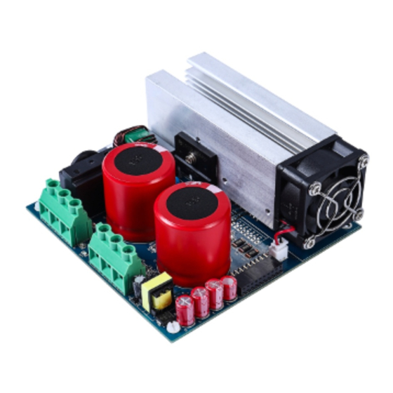
EVAL-M1-CTE620N3 User Manual iMOTION™ Modular Application Design Kit EVAL-M1-CTE620N3 main features EVAL-M1-CTE620N3 board specifications Table 2 depicts the important specifications of the evaluation board EVAL-M1-CTE620N3. Table 2 EVAL-M1-CTE620N3 board specifications Parameters Values Conditions / comments Input Voltage 165 - 265 V... - Page 8 Figure 2 Show the relationship between Output Power and Heatsink Temperature. Figure 2 The relationship between Output Power and Heatsink Temperature Figure 3 points out the functional groups on the top side of the EVAL-M1-CTE620N3 evaluation board. 1. J1 - AC Input connector 2. J3 - Motor phase connector 3.
-
Page 9: Pin Assignment
EVAL-M1-CTE620N3 User Manual iMOTION™ Modular Application Design Kit EVAL-M1-CTE620N3 main features Figure 4 points out the functional groups on the bottom side of the EVAL-M1-CTE620N3 evaluation board. 11. ICE5GR4780AG U1 12. Auxiliary power supply Current sensing shunt resistor RS1, RS2 13. - Page 10 EVAL-M1-CTE620N3 User Manual iMOTION™ Modular Application Design Kit EVAL-M1-CTE620N3 main features Ground PWMUL 3.3 V compatible logic input for low side gate driver-Phase U 4 GND Ground PWMVH 3.3 V compatible logic input for high side gate driver-Phase V +3.3V On board 3.3 V supply...
-
Page 11: Getting Started With Eval-M1-Cte620N3
Getting Started with EVAL-M1-CTE620N3 Getting Started with EVAL-M1-CTE620N3 In order to run the motor system, a combination of the iMOTION™ MADK power board (EVAL-M1-CTE620N3) and the matching MADK control board is required. The iMOTION™ Software Tools MCEDesigner and MCEWizard are also required in order to initialy setup the system, as well as to control and fine-tune the system performance to match users exact needs. - Page 12 EVAL-M1-CTE620N3 User Manual iMOTION™ Modular Application Design Kit Getting Started with EVAL-M1-CTE620N3 9. Program the MCE Firmware and system parameters into the internal Flash memory of iMOTION™ IC by clicking “Tools > Programmer “in the pull down menu, and then clicking on the “Program Firmware and Parameter”...
-
Page 13: Imotion™ Development Tools And Software
“Welcome Page” for MCEWizard, where the MADK control board or power board can be selected through the pull-down list. Infineon keeps releasing new MADK controller and power boards. Therefore, it could happen that some of the newest power boards are not pre-configured in the MCEWizard tool and cannot be selected through the pull-down menu. - Page 14 EVAL-M1-CTE620N3 User Manual iMOTION™ Modular Application Design Kit Getting Started with EVAL-M1-CTE620N3 available in each power board’s User Manual. Combination of this table and the corresponding table of the power board provides enough information to setup the MADK-based motor drive system in shortest time.
-
Page 15: Mcedesigner Setup Overview
EVAL-M1-CTE620N3 User Manual iMOTION™ Modular Application Design Kit Getting Started with EVAL-M1-CTE620N3 4.2.2 MCEDesigner setup overview After installing MCEDesigner installer, there is a shortcut for MCEDesigner on Windows desktop. Double click the shortcut to open MCEDesigner and then open “IMC101T_xx.irc” file as shown in Table 7. - Page 16 File”. Finally, click on the “Start” button to program the parameter file into the IMC101T-T038 IC. Figure 10 Program Firmware and Parameter in “Program IMC Controller” pop-up window All latest firmware file for different type of iMOTION control ICs are available for download via Infineon iMOTION website (http://www.infineon.com/imotion-software). User Manual 16 of 37 Revision 1.0...
-
Page 17: Hardware Description Of Eval-M1-Cte620N3
The inverter section is also implemented using the CIPOS™ Tiny IPM as sketched in Figure 11. This advanced IPM is a combination of Infineon’s newest low VCE(on) Trench IGBT technology optimized for best trade-off between conduction and switching losses and the industry benchmark 3 phase high voltage, high speed driver (3.3V compatible) in a fully isolated thermally enhanced package. -
Page 18: Dc Bus Sensing And Mcewizard Configuration
DCBSense voltage results in the range of 0 to 3.3 V on the pin reflecting a DC bus voltage range of 0 to 420 V.If a pull down resistor of 13.3 kΩ is inserted on both, EVAL-M1-CTE620N3 evaluation board and on the control card, the DCBSense results scale to 0-1.65 V. -
Page 19: Motor External Current Feedback Configuration And Calculation
EVAL-M1-CTE620N3 User Manual iMOTION™ Modular Application Design Kit Hardware description of EVAL-M1-CTE620N3 Figure 13 DC bus sensing configuration in MCEWizard 5.1.2 Motor External Current feedback configuration and calculation The current input value is product of the shunt resistance in milliohms and gain of External current sense amplifier for EVAL-M1-101T as shown in Figure 14. - Page 20 Please use same procedure to calculate the current input for other combinations of MADK boards and enter it into MCEWizard as shown in Figure 16. Figure 16 Current feedback configuration in MCEWizard for EVAL-M1-101T and EVAL-M1-CTE620N3 User Manual 20 of 37 Revision 1.0...
-
Page 21: Inverter Overcurrent Protection And Motor Gatekill Configuration
4700pF 16V 4700pF 16V +15VCC 10uF 16V Figure 17 Overcurrent protection circuit on the EVAL-M1-CTE620N3 evaluation board The typical value of ITRIP positive going threshold V is 300mV. So the inverter output peak current is about IT, TH+ 14.7Apeak. ∗... -
Page 22: Thermistor/Ntc Characteristics And Protection Calculation
EVAL-M1-CTE620N3 User Manual iMOTION™ Modular Application Design Kit Hardware description of EVAL-M1-CTE620N3 Thermistor/NTC Characteristics and protection calculation This board provides Thermistor/NTC output on pin 15 of the 20 pins connector J2. Temperatures can be calculated by resistor measurement. 5.2.1 CIPOS™ Internal NTC – Thermistor Characteristics The thermistor characteristics for CIPOS™... -
Page 23: Overtemperature Hardware Protection Circuit
Thermistor readout vs.temperature(with 4.7kohm Rext pull-down resistor)and typical thermistor resistance values vs.temperature table 5.2.2 Overtemperature Hardware Protection Circuit In this evaluation design kits EVAL-M1-CTE620N3 and EVAL-M1-101T, the VTH pin is directly connected to the VTH pin for controller IC IMC101T. +3.3V TP10 IM393-X6E 4.87Kohm 1/8W 1%... -
Page 24: Ntc Shutdown Value Calculation And Configuration
IM393 are 4.87kΩ and 2.902kΩ (see Figure 20). The typical value of R at 100°C is THERM 2.902kΩ for IPM IM393 which is used in EVAL-M1-CTE620N3. ℎ ℎ If the setting temperature is 100°C, the shutdown value should be 1.23V. If the setting temperature is 85°C, the shutdown value should be 1.62V. -
Page 25: Auxiliary Power Supply
Hardware description of EVAL-M1-CTE620N3 Auxiliary power supply Figure 22 depicts the schematic of the auxiliary power supply for the EVAL-M1-CTE620N3 board. The circuit includes the latest CoolSET 5 of Infineon and flyback toplogy, directly output 15V and 6V. V is connected to the gate drivers inside the CIPOS™... -
Page 26: Schematics For Eval-M1-Cte620N3
EVAL-M1-CTE620N3 User Manual iMOTION™ Modular Application Design Kit Hardware description of EVAL-M1-CTE620N3 Schematics for EVAL-M1-CTE620N3 The AC linear setion schematic for EVAL-M1-CTE620N3 is provided in Figure 23. DCBUS 10A 250V DCBUS NTC/5D-20 100Kohm 1/2W 5% 3300pF 250VAC 500Kohm 1/8W 1% 0.47uF 275VAC... - Page 27 EVAL-M1-CTE620N3 User Manual iMOTION™ Modular Application Design Kit Hardware description of EVAL-M1-CTE620N3 The Auxiliary Power Supply setion schematic for EVAL-M1-CTE620N3 is provided in Figure 25. R19 DNI +15V 2.7uH 4A SS3H10-E3/9AT-3A/100V 68k 1/4W 1nF 630V ECAP 25V 330uF 8*3.5 ECAP 25V 330uF 8*3.5 3.3V...
-
Page 28: Pcb Layout For Eval-M1-Cte620N3
Gerber-files. Figure 26 illustrates the top assembly print of the evaluation board. Figure 26 Top assembly print of the EVAL-M1-CTE620N3 evaluation board Figure 27 depicts the bottom assembly print of the evaluation board. User Manual 28 of 37 Revision 1.0... - Page 29 EVAL-M1-CTE620N3 User Manual iMOTION™ Modular Application Design Kit Hardware description of EVAL-M1-CTE620N3 Figure 27 Bottom assembly print of the EVAL-M1-CTE620N3 evaluation board User Manual 29 of 37 Revision 1.0 2018-08-23...
- Page 30 EVAL-M1-CTE620N3 User Manual iMOTION™ Modular Application Design Kit Hardware description of EVAL-M1-CTE620N3 The top layer routing of the PCB is provided in Figure 28. Figure 28 Top layer routing of the EVAL-M1-CTE620N3 User Manual 30 of 37 Revision 1.0 2018-08-23...
- Page 31 EVAL-M1-CTE620N3 User Manual iMOTION™ Modular Application Design Kit Hardware description of EVAL-M1-CTE620N3 Figure 29 illustrates the bottom layer routing of the PCB. Figure 29 Bottom layer routing of the EVAL-M1-CTE620N3 User Manual 31 of 37 Revision 1.0 2018-08-23...
- Page 32 EVAL-M1-CTE620N3 User Manual iMOTION™ Modular Application Design Kit Hardware description of EVAL-M1-CTE620N3 Table 9 provides the complete bill of materials for the EVAL-M1-CTE620N3. Table 9 Bill of materials Part description Designator Part number Manufacturer LLG2G471MELC ECAP ALUM 470μF 400V RADIAL E1,E2 Wurth Electronics Inc.
- Page 33 EVAL-M1-CTE620N3 User Manual iMOTION™ Modular Application Design Kit Hardware description of EVAL-M1-CTE620N3 Part description Designator Part number Manufacturer 07100KL RC1206JR- RES SMD 3MΩ 5% 1/4W 1206 R11,R12,R13 Yageo 073ML RC1206FR- RES SMD 65kΩ 5% 1/4W 1206 Yageo 0765KL RC1206JR- RES SMD 15MΩ 5% 1/4W 1206...
- Page 34 EVAL-M1-CTE620N3 User Manual iMOTION™ Modular Application Design Kit Hardware description of EVAL-M1-CTE620N3 Part description Designator Part number Manufacturer IC COMPARATOR VOLT SGL SOT LM397 Texas Instruments IC CIPOS Tiny Module U6/U7 IM393-X6E/F Infineon Technologies DIODE ZENER 22V 500mW SOD123 MMSZ525B-7-F Wurth Electronics Inc.
-
Page 35: Reference
AN2018-02 EVAL-M1-101T User manual MCEWizard User Guide MCEDesigner User Guide Note: All listed reference materials are available for download on Infineon’s website www.infineon.com/. All the iMOTION MADK evaluation board’s User Manuals are available at www.infineon.com/MADK All the CIPOS™ IPM’s Datasheets and documents are available at www.infineon.com/IPM. -
Page 36: Revision History
EVAL-M1-CTE620N3 User Manual iMOTION™ Modular Application Design Kit Reference Revision history Document Date of release Description of changes version 2018-08-27 First Release User Manual 36 of 37 Revision 1.0 2018-08-23... -
Page 37: Www.infineon.com
Do you have a question about this Except as otherwise explicitly approved by Infineon information given in this application note. Technologies in a written document signed by...
Need help?
Do you have a question about the EVAL-M1-CTE620N3 and is the answer not in the manual?
Questions and answers