Table of Contents
Advertisement
Quick Links
Advertisement
Table of Contents

Related Manuals for Crestron CHV-RSS


Summary of Contents for Crestron CHV-RSS
- Page 1 Crestron CHV-RSS Remote Slab Sensor Installation Guide...
- Page 2 This document was prepared and written by the Technical Documentation department at: Crestron Electronics, Inc. 15 Volvo Drive Rockleigh, NJ 07647 1-888-CRESTRON All brand names, product names and trademarks are the property of their respective owners. ©2005 Crestron Electronics, Inc.
-
Page 3: Table Of Contents
Mounting Position ...3 Slab Sensor Mounting in Tile or Wood Floors ...5 Tile Floor Mounting ...5 Wood Floor Mounting ...5 Hardware Hookup ...6 Using the CHV-RSS as an Outdoor Temperature Sensor ...7 Problem Solving...9 Troubleshooting...9 Further Inquiries ...9 Future Updates...10 Return and Warranty Policies ...11... -
Page 5: Remote Slab Sensor: Chv-Rss
Thermostat firmware version 2.xx and later supports four optional remote sensor inputs, in any combination, for each thermostat. Firmware version 2.xx and later is required if you want to use the CHV-RSS as a slab Installation Guide - DOC. 6229A Remote Slab Sensor ®... -
Page 6: Specifications
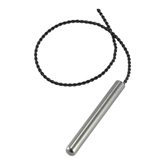
Refer to the illustrations below and on the following page. The sensor has a diameter of 0.32 inch (7.92 mm) and is 2.75 inches (6.98 cm) long. The CHV-RSS remote sensor is contained in a cylindrical stainless steel housing. CHV-RSS NOTE: The sensor determines the temperature using the entire surface of its steel housing. -
Page 7: Industry Compliance
0.312 in diameter (7.92 mm) Industry Compliance As of the date of manufacture, the CHV-RSS has been tested and found to comply with specifications for CE marking and standards per EMC and Radiocommunications Compliance Labelling. NOTE: This device complies with part 15 of the FCC rules. Operation is... - Page 8 • The sensor should be placed midway between the heating elements. Sensor Position – Top View Midway Between Heating Elements or Pipes 4 • Remote Slab Sensor: CHV-RSS Sensor Conduit Slab Heating Cables or Pipes Floor Installation Guide – DOC. 6229A...
-
Page 9: Slab Sensor Mounting In Tile Or Wood Floors
Wood Floor Mounting Installation Guide - DOC. 6229A Remote Slab Sensor Tiles (finished surface) Thin-set Mortar Heating Cables or Pipes Subfloor Floor Joists Slab Sensor Wood Floor Subfloor Floor Joists Slab Sensor Heating Cables or Pipes Remote Slab Sensor: CHV-RSS • 5... -
Page 10: Hardware Hookup
Connection Example 1: Connecting one air temperature/humidity sensor and one slab sensor (a CHV-RTS or a CHV-RTHS and a CHV-RSS) to the thermostat, each on its own channel. NOTE: Sensor wiring is non-polarized 1. -
Page 11: Using The Chv-Rss As An Outdoor Temperature Sensor
(CHV-RTS) and two floor temperature sensors (CHV-RSS) to the thermostat. CHV-RTS CHV-RTS NOTE: In this example, two CHV-RSS slab sensors are used for temperature averaging in a large room. Using the CHV-RSS as an Outdoor Temperature Sensor The rugged waterproof construction, stainless steel housing, and high degree of accuracy make this sensor ideal for outdoor use. - Page 12 3. Form a drip loop in the wire to prevent moisture from entering the building. Suggested Mounting Illustration Coaxial Cable Standoff Feedthrough Bushing 8 • Remote Slab Sensor: CHV-RSS CHV-RSS Silicon Adhesive Coaxial Cable Standoffs Twisted Pair Feedthrough...
-
Page 13: Problem Solving
Crestron website (www.crestron.com) for a listing of Crestron worldwide offices. You can also log onto the online help section of the Crestron website to ask questions about Crestron products. First-time users will need to establish a user account to fully benefit from all available features. -
Page 14: Future Updates
Remote Slab Sensor Future Updates As Crestron improves functions, adds new features, and extends the capabilities of the CHV-RSS, additional information may be made available as manual updates. These updates are solely electronic and serve as intermediary supplements prior to the release of a complete technical documentation revision. -
Page 15: Return And Warranty Policies
CRESTRON shall not be liable to honor the terms of this warranty if the product has been used in any application other than that for which it was intended, or if it has been subjected to misuse, accidental damage, modification, or improper installation procedures. - Page 16 Crestron Electronics, Inc. Installation Guide – DOC. 6229A 15 Volvo Drive Rockleigh, NJ 07647 (2009402) Tel: 888.CRESTRON 04.05 Fax: 201.767.7576 Specifications subject to www.crestron.com change without notice.
Need help?
Do you have a question about the CHV-RSS and is the answer not in the manual?
Questions and answers