Table of Contents
Advertisement
Quick Links
CRESTRON CNCS
FRONT PANEL
AC OUTPUT
CW = INCREASED THRESHOLD
1000 W
MAX
DESCRIPTION:
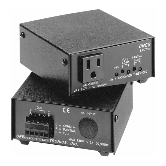
The CNCS, illustrated in figure 1, measures the average current of each half cycle of an AC load.
The current sensing circuitry is highly sensitive with a wide range of adjustment. The high
sensitivity makes the CNCS ideally suited for use with low power units such as VCRs, TV tuners,
and satellite receivers. The wide range makes the CNCS ideally suited for medium and high
powered units such as TV sets, video projectors, and power amplifiers.
The CNCS provides an isolated relay closure when the average current drawn by a monitored unit
exceeds the FULL LOAD preset threshold.
A second set of relay contacts determine whether the average current is less than FULL LOAD,
but more than no load. This PARTIAL LOAD threshold is also adjustable. The FULL LOAD and
PARTIAL LOAD relay closures are mutually exclusive so that only one closure is ever connected to
the common. However, FULL LOAD and PARTIAL LOAD indicators are implemented, so that at
FULL LOAD, both LEDs are illuminated.
Threshold Adjustments are accomplished by use of a 15-turn precision potentiometer (POT). The
POT permits highly accurate and repeatable current threshold settings.
LEADING SPECIFICATIONS:
Table 1 provides a summary of leading specifications for the CNCS. Dimensions and weight are
approximations rounded to the nearest tenth unit.
SPECIFICATION
Power Requirements
Maximum AC Load
Minimum AC Load
Voltage Range
Relay Contact Rating
R E M O T E
C O N T R O L
S Y S T E M S
CNCS
FULL
PARTIAL
LOAD
LOAD
PWR
Figure 1.
CNCS, AC Current Sensor
Table 1. Leading Specifications
Specifications subject to change without notice.
OUT
CRESTRON
ELECTRONICS,
DETAILS
24 VDC, Load Factor of 3 W
8.5 A, 1 KW at 120 VAC
0.033 A, 4 W at 120 VAC
0 to 220 VAC, 45 to 65 Hz
1 A, 24 V (AC or DC)
1
AC Current Sensor
BACK PANEL
AC INPUT
C
COMMON
P
PARTIAL
F
FULL
1000 W MAX
INC.
DOC. 8079C
Advertisement
Table of Contents

Subscribe to Our Youtube Channel
Related Manuals for Crestron CNCS


Summary of Contents for Crestron CNCS
- Page 1 Figure 1. DESCRIPTION: The CNCS, illustrated in figure 1, measures the average current of each half cycle of an AC load. The current sensing circuitry is highly sensitive with a wide range of adjustment. The high sensitivity makes the CNCS ideally suited for use with low power units such as VCRs, TV tuners, and satellite receivers.
- Page 2 Clockwise rotation of the 15-turn POT increases threshold (i.e., reduces sensitivity). THRESHOLD ADJUSTMENTS: Refer to figure 2 for a block diagram illustrating hookup connections for the CNCS. NOTES 1. Do not attempt adjustments during periods of high or low power line voltage or voltage fluctuations.
- Page 3 CNCS AC OUTPUT EQUIPMENT TO BE SENSED Figure 2. CNCS, Hookup Block Diagram Low Power (Loads such as VCRs) 1. Rotate FULL LOAD POT 15 turns counterclockwise (CCW). 2. Rotate PARTIAL LOAD POT 15 turns CCW. 3. Place VCR in "ON" mode. Red and yellow LEDs should illuminate.
- Page 4 CRESTRON CNCS NOTE If the LED flash and relay chatter can not be achieved in step 6, start procedure again with step 1. After performing step 4, rotate FULL LOAD POT two turns CCW. Continue procedure with step 5, omitting steps 6 and 7.
- Page 5 CRESTRON CNCS PROGRAMMING: A basic CNCS SIMPL program is illustrated in figure 4. The sample program illustrates discrete ON/OFF for toggle type IR control. NOTE The program example is provided as a sample of CNCS implementation and may not be relevant for every application.
- Page 6 CRESTRON CNCS Program Example: CNDIO Signal Assignment Rack: FULL-LOAD PARTIAL-LOAD F2-Detail back CNIN-16 Signal Assignment Rack: FULL-LOAD PARTIAL-LOAD F2-Detail back R E M O T E C O N T R O L S Y S T E M S Specifications subject to change without notice.
Need help?
Do you have a question about the CNCS and is the answer not in the manual?
Questions and answers