Table of Contents
Advertisement
Advertisement
Table of Contents

Related Manuals for Crestron CH-TEMP-WM


Summary of Contents for Crestron CH-TEMP-WM
- Page 1 Crestron CH-TEMP-WM Temperature sensor Operation Guide...
-
Page 2: Table Of Contents
Configuration Manager................ 7 Programming Manager..............8 Example Program................8 Show temperature on a Touchpanel……………………………… 8 Problem Solving Troubleshooting...................9 Futher Inquiries..................10 Crestron International • 2 Oude Keerbergsebaan • 2820 Rijmenam • Belgium Tel: +32 15 50 99 50 • info@crestron-int.be • www.crestron-int.be... -
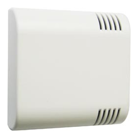
Page 3: Description
• Fits in a standard European 1-gang electrical box (55 – 65 mm diameter). • Bleu LED feedback for power indication. Applications: Heating / cooling Temperature display Crestron International • 2 Oude Keerbergsebaan • 2820 Rijmenam • Belgium Tel: +32 15 50 99 50 • info@crestron-int.be • www.crestron-int.be... -
Page 4: Technical Data
(with jumper for LED on / off) Includes Interface with 2x 4-pole mini phoenix connections. General view Figure 2: Cresnet connection Figure 3: Mounting view Crestron International • 2 Oude Keerbergsebaan • 2820 Rijmenam • Belgium Tel: +32 15 50 99 50 • info@crestron-int.be • www.crestron-int.be... -
Page 5: Setup
CH-TEMP-MW Product Manual Cresnet Connections Note: Before making any connections, CRESTRON recommends that all power is off and the installer reviews the latest revision of the network interconnection drawing (DOC5411i). Refer to figure 4 and connect the CH-TEMP-MW to the Cresnet network via a Cresnet network cable (CRESNET cable). -
Page 6: Cresnet Id
Figure 5: NET ID rotary switch Power Feedback When the CH-TEMP-WM is connected to the cresnet (see page 5) a bleu LED will illuminate. This bleu LED can be disconnected by removing the jumper that is located next to the rotary switch. When this jumper is removed the CH-TEMP-WM will keep on working but no LED feedback will be shown. -
Page 7: Programming
Configuration manager A CH-TEMP-MW needs to be defined as a CNTS-N in Simpl Windows (Figure 6). Figure 6: Hardware configuration Crestron International • 2 Oude Keerbergsebaan • 2820 Rijmenam • Belgium Tel: +32 15 50 99 50 • info@crestron-int.be • www.crestron-int.be... -
Page 8: Programming Manager
For each type of readout, different scaler settings are needed. Figure 8: Example program Crestron International • 2 Oude Keerbergsebaan • 2820 Rijmenam • Belgium Tel: +32 15 50 99 50 • info@crestron-int.be • www.crestron-int.be... -
Page 9: Problem Solving
Troubleshooting Table 1 Provides corrective action for possible trouble situations. If further assistance is required, please contact a Crestron Technical Support representative or submit your question on the Crestron True Blue On Line Service (www.crestron.com) Table 1: Troubleshooting Guide POSSIBLE CAUSE(S) -
Page 10: Futher Inquiries
If after reviewing this Operations Guide on the CH-TEMP-MW , you cannot locate specific information or have questions, please take advantage of Crestron's award winning customer service team by calling: • In Europe, call Crestron International at +32-15-50-99-50. • In the UK, call Crestron UK at +44-20.845.74.007.
Need help?
Do you have a question about the CH-TEMP-WM and is the answer not in the manual?
Questions and answers