
Related Manuals for Cypress CYW943907AEVAL1F


Summary of Contents for Cypress CYW943907AEVAL1F
-
Page 1: Cyw943907Aeval1F
CYW943907AEVAL1F Evaluation Kit User Guide Doc. No. 002-18703 Rev. *A Cypress Semiconductor 198 Champion Court San Jose, CA95134-1709 www.cypress.com CYW943907AEVAL1F Evaluation Kit User Guide, Doc. No. 002-18703 Rev. *B... - Page 2 Cypress is not liable, in whole or in part, and you shall and hereby do release Cypress from any claim, damage, or other liability arising from or related to all Unintended Uses of Cypress products.
-
Page 3: Table Of Contents
Micro SD Connector/Slot ............................. 32 JTAG Connector ..............................33 Connectors ................................33 UART Port Configuration on CYW943907AEVAL1F Kit ..................35 External ADC ............................... 36 4.10 PWM ..................................37 Code Examples ................................39 CYW943907AEVAL1F Evaluation Kit User Guide, Doc. No. 002-18703 Rev. *B... - Page 4 Contents AWSIOTPubSub Project ............................. 39 WiFiScanner ................................ 49 Revision History ................................... 50 CYW943907AEVAL1F Evaluation Kit User Guide, Doc. No. 002-18703 Rev. *B...
-
Page 5: Safety Information
Handling Boards CYW943907AEVAL1F boards are sensitive to ESD. Hold the board only by its edges. After removing the board from its box, place it on a grounded, static-free surface. Use a conductive foam pad if available. Do not slide the board over any surface. -
Page 6: Introduction
WICED Studio-based development flow. The CYW943907AEVAL1F EVK offers footprint-compatibility with Arduino shields. In addition, the kit features an RJ-45 Ethernet connector, a micro-SD-card slot, and onboard programmer/debugger and serial bridge chip. The CYW943907AEVAL1F EVK supports only 3.3 V as the operating voltage. - Page 7 Introduction Figure 1-1. CYW943907AEVAL1F Kit Contents Inspect the contents of the kit. If you find any part missing, contact your nearest Cypress sales office for assistance: www.cypress.com/support. Hardware Not Included with the Kit The CYW943907AEVAL1F EVK does not come with all the hardware needed to perform the demonstrations documented in this guide.
-
Page 8: Cyw943907Aeval1F Board Details
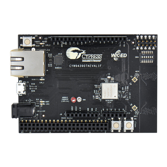
Introduction 1.2 CYW943907AEVAL1F Board Details The CYW943907AEVAL1F board consists of the blocks shown in Figure 1-2 and Figure 1-3. Reset Switch (SW2) RJ-45 Connector (J14) Micro USB (Programming and Debugging) (J5) 5–12 V Power Input (J8) WICED Header (J6) Arduino Header (J13) -
Page 9: Modus Toolbox Overview
Figure 1-4. WICED IDE 1.3 Modus Toolbox Overview ModusToolbox is a set of tools that enable you to integrate Cypress devices into your existing development methodology. One of the tools is a multi-platform, Eclipse-based Integrated Development Environment (IDE) that supports configuration and application development, called Modus IDE. -
Page 10: Getting Started
IoT device for your design, and quickly and effectively integrate the device into your design. Cypress provides customer access to a wide range of information, including technical documentation, schematic diagrams, product bill of materials, PCB layout information, and software updates. -
Page 11: Additional Learning Resources
Introduction 1.6 Additional Learning Resources Visit CYW943907AEVAL1F EVK and CYW43907 for additional learning resources including datasheets and application notes. 1.7 Document Conventions Table 1-1. Document Conventions for Guides Convention Usage Displays file locations, user entered text, and source code: Italics C:\ ...cd\icc\... -
Page 12: Software Installation
This chapter provides instructions for installing the ModusToolbox software – a set of tools that enables you to integrate Cypress devices into your existing development methodology. This is a Beta release of ModusToolbox, and it is only available through the ModusToolbox Early Access Program (EAP) website. - Page 13 Navigate to the directory where you moved the ModusToolbox.app file (e.g., /Applications/ModusToolbox) and run ModusToolbox.app. When the Modus IDE runs for the first time, a dialog opens to specify the Workspace location. The default location for the workspace is: [user_home]\mtw. CYW943907AEVAL1F Evaluation Kit User Guide, Doc. No. 002-18703 Rev. *B...
- Page 14 Refer to the Quick Start Guide for brief instructions to create, build, and program projects. Refer also to the Modus IDE User Guide for more detailed information. These documents are available from the ModusToolbox EAP website. CYW943907AEVAL1F Evaluation Kit User Guide, Doc. No. 002-18703 Rev. *B...
-
Page 15: Kit Operation
3. Kit Operation This chapter introduces you to the CYW943907AEVAL1F EVK and the features that will be used as part of the kit operation. Features such as Wi-Fi connection and programming/debugging are discussed in this chapter. The chapter also describes the USB-UART bridge that can be used to communicate with the CYW43907 device on this EVK. -
Page 16: Cyw943907Aeval1F Kit Connection
3.3 CYW943907AEVAL1F Kit Connection The CYW943907AEVAL1F EVK can be powered by either an external power supply or through USB. When using an external power supply, use a 5 V–12 V, 2 A power supply with a 2.1-mm DC Jack (center pin positive). When powered from USB, there are two logical USB devices: a USB-JTAG device and a USB-UART device. - Page 17 If an error occurs during the automatic driver installation process, the driver may be manually installed from the following directory: <WICED-SDK>\Drivers\Windows\wiced_uart. If the CYW943907AEVAL1F EVK does not appear in Device Manager, verify that the +3V3 LED (D2) is turned ON, and check the USB cable.
-
Page 18: Building, Programming, And Debugging Cyw943907Aeval1F Evk
3.4.1 Building and Programming a Project for CYW943907AEVAL1F in ModusToolbox To build and program a project for CYW943907AEVAL1F EVK, do the following: Launch Modus IDE. Run the “ModusToolbox” executable file to launch the IDE as applicable for your operating system. - Page 19 The dialog displays a list of boards, showing the Kit Name, MCU, and Radio (if applicable), and shows a description of the board that you select. For this example, select the CYW943907AEVAL1F board. CYW943907AEVAL1F Evaluation Kit User Guide, Doc. No. 002-18703 Rev. *B...
- Page 20 In this case, “WiFiScanner” is the default name. Click Next to open the Summary page. This page shows the options chosen for this project. Review them to ensure that they are correct. CYW943907AEVAL1F Evaluation Kit User Guide, Doc. No. 002-18703 Rev. *B...
- Page 21 Click Finish to create the project. After a few moments, the Modus IDE displays the progress information. When complete, project folders appear in the Project Explorer pane as Figure 3-11 shows. CYW943907AEVAL1F Evaluation Kit User Guide, Doc. No. 002-18703 Rev. *B...
- Page 22 Build Starter Project. After loading a project,. select Project > Build All (or press Ctrl+B). Figure 3-12. Build Project Messages appear in the console, indicating whether the build was successful (see Figure 3-13). CYW943907AEVAL1F Evaluation Kit User Guide, Doc. No. 002-18703 Rev. *B...
- Page 23 Do the following to view output messages with a terminal emulation program (such as Tera Term): Start the terminal emulation program. Set Terminal ID to VT100 and New-Line Receive to AUTO. Leave other settings at their default values. CYW943907AEVAL1F Evaluation Kit User Guide, Doc. No. 002-18703 Rev. *B...
- Page 24 Note: The exact port number will vary with the corresponding PC port. Figure 3-16. Serial Port Setup Press the Reset button (see Figure 1-1) on the CYW943907AEVAL1F EVK to view application startup messages. The terminal emulation program should look similar to Figure 3-17.
- Page 25 3.4.2 Debugging a Project for CYW943907AEVAL1F in ModusToolbox Click the Debug button. The first time you do this, the Debug Configurations dialog appears. You can select the appropriate configuration to use for debugging. CYW943907AEVAL1F Evaluation Kit User Guide, Doc. No. 002-18703 Rev. *B...
- Page 26 If required, the IDE builds the project and messages display in the console. If the build is successful, the IDE switches to debug mode automatically. If there are build errors, error messages appear. When a successful build is completed, the Modus IDE switches to debug mode as shown in Figure 3-19. CYW943907AEVAL1F Evaluation Kit User Guide, Doc. No. 002-18703 Rev. *B...
- Page 27 Kit Operation Figure 3-19 Modus IDE Debug Window CYW943907AEVAL1F Evaluation Kit User Guide, Doc. No. 002-18703 Rev. *B...
-
Page 28: Hardware
4. Hardware This chapter describes the CYW943907AEVAL1F EVK hardware and its different blocks, such as Bootstrap, reset control, Arduino-compatible headers, and module connectors. The schematic is available as part of the CYW943907AEVAL1F Hardware Files.zip file at http://www.cypress.com/documentation/development-kitsboards/cyw943907aeval1f-evaluation-kit. Bootstrap options available in the CYW943907AEVAL1F EVK are shown in Table 4-1. -
Page 29: User Switches
Figure 4-3. The CYW43907/BCM43907 datasheet states that HIB_REG_ON_IN needs to be delayed by at least two cycles of the 32.768-kHz clock after VBAT and VDDIO have reached CYW943907AEVAL1F Evaluation Kit User Guide, Doc. No. 002-18703 Rev. *B... -
Page 30: Ethernet
Table 4-4. CYW43907 EMAC to PHY Chip Connection Sl.No. CYW43907 Pin Name Net Name in Schematic BCM5241 Pin Name RMII_G_RXC MII_RXC RMII_G_COL MII_COL COL/ENERGYDET RMII_G_CRS MII_CRS CRS/STANDBY RMII_G_TXC MII_TXC_RMII_REF_CLK RMII_G_TXD0 MII_TXD0 TXD0 CYW943907AEVAL1F Evaluation Kit User Guide, Doc. No. 002-18703 Rev. *B... - Page 31 TXD2 RMII_G_TXD3 MII_TXD3 TXD3 RMII_G_RXD0 MII_RXD0 RXD0/PHYAD0 RMII_G_RXD1 MII_RXD1 RXD1/ANEN_L RMII_G_RXD2 MII_RXD2 RXD2/F100 RMII_G_RXD3 MII_RXD3 RXD3/ISOLATE RMII_MDIO MII_MDIO MDIO RMII_MDC MII_MDC RMII_G_TXEN MII_TXEN TXEN RMII_G_RXDV MII_RXDV_CRS_DV RXDV PWM_2 PWM_2 RESET_L CYW943907AEVAL1F Evaluation Kit User Guide, Doc. No. 002-18703 Rev. *B...
-
Page 32: Micro Sd Connector/Slot
4-5. Table 4-5. Micro SD Connector signals S No CYW43907 Based SIP Pin Name Micro SD Connector/Slot Name SDIO_DATA_0 DAT0 SDIO_DATA_1 DAT1 SDIO_DATA_2 DAT2 SDIO_DATA_3 CD/DAT3 SDIO_CMD SDIO_CLK PWM_0 DETECT CYW943907AEVAL1F Evaluation Kit User Guide, Doc. No. 002-18703 Rev. *B... -
Page 33: Jtag Connector
4.7 Connectors 4.7.1 WICED Header J6 is the WICED header available on the CYW943907AEVAL1F EVK. This is a 44-pin header containing I C, SDIO, UART, SPI, PWM lines, and I/Os. Note that some signals are shared with the Arduino header (UART0 Tx/Rx) and Onboard Programmer/debugger chip (UART1). - Page 34 USB2_DN J6.44 USB2_DP 4.7.2 Arduino-Compatible Headers J9, J13, J12, and J10 are Arduino headers available in the CYW943907AEVAL1F EVK. Table 4-8 shows the pinout of the Arduino header. Note the following points while connecting an Arduino shield to the board: ▪...
-
Page 35: Uart Port Configuration On Cyw943907Aeval1F Kit
UART is a 4-wire interface that can support up to a 3-Mbps baud rate. Slow UART is routed to the onboard programmer/debugger chip for UART-to-USB communication. UART peripherals are defined in the following file: CYW943907AEVAL1F Evaluation Kit User Guide, Doc. No. 002-18703 Rev. *B... -
Page 36: External Adc
Hardware <installed_location>/ModusToolbox_1.0/libraries/wiced_base-1.0/components/WIFI-SDK/platforms/ CYW943907AEVAL1F/platform.c. The following table (also available in platforms/CYW943907AEVAL1F/platform.h) shows the UART pins available on the kit. Table 4-9. HEADER SDK PERIPHERAL PIN NAME ON MURATA MODULE PIN NAME ENUMERATION ID CYW43907 ENUMERATION NUMBER WICED_PERIPHERAL_PIN_1 Rf_sw_ctrl_6 Rf_sw_ctrl_6_uart1_rxd j6:36 Wiced_uart_1... -
Page 37: Pwm
There are six dedicated PWM outputs available on CYW43907. These PWMs can be multiplexed onto different pins. You can find their definitions in platforms/CYW943907AEVAL1F/platform.c. These PWMs can be reassigned to other pins by changing the first argument of the platform_pwm_t platform_pwm_peripherals structure in platform.c. - Page 38 SELECTION NAME PIN_GPIO_7 J10.4.4 Arduino D3 (DEFAULT) PIN_GPIO_1 J10.1 Arduino D0 PIN_GPIO_9 J12.9 Arduino SCK PIN_GPIO_11 J12.3 Arduino D10 PIN_GPIO_13 J10.3 Arduino D2 PIN_GPIO_15 J10.7 Arduino D6 PIN_PWM_5 CYW943907AEVAL1F Evaluation Kit User Guide, Doc. No. 002-18703 Rev. *B...
-
Page 39: Code Examples
5. Code Examples This chapter demonstrates the functionality of CYW43907 devices using CYW943907AEVAL1F EVK code examples. The code examples are already bundled with the SDK, which can be found in <InstallationFolder>\ModusToolbox_1.0\libraries\wiced_base-1.0\examples\apps\snips. Code examples can be compiled after creating the ModusToolbox project. Refer to... - Page 40 Open https://aws.amazon.com and choose Create an AWS Account. Follow the online instructions. Part of the sign-up procedure involves receiving a phone call and entering a PIN using the phone keypad. CYW943907AEVAL1F Evaluation Kit User Guide, Doc. No. 002-18703 Rev. *B...
- Page 41 Note: It is possible to exchange messages without a need to create a Thing (by having a certificate with an attached policy), but AWS recommends that you create a Thing. CYW943907AEVAL1F Evaluation Kit User Guide, Doc. No. 002-18703 Rev. *B...
- Page 42 In Add a certificate for your thing window, select Create thing without certificate. Figure 5-4. Add a Certificate to Your Thing You will see your Thing successfully created on Things window. CYW943907AEVAL1F Evaluation Kit User Guide, Doc. No. 002-18703 Rev. *B...
- Page 43 (in our case, “943907_led_onoff” is the one defined as WICED_TOPIC macro in publish_subscribe.c), use the following Resource ARN “arn:aws:iot:us-east- 1:xxxxxxxxxxxx:943907_led_onoff”. Select the check box Allow Effect as shown in Figure 5-6. CYW943907AEVAL1F Evaluation Kit User Guide, Doc. No. 002-18703 Rev. *B...
- Page 44 In the AWS IoT Console window, go to Manage > Things and then click on the created thing (for example, 943907_aws). The created Thing window appears. In the left navigation pane, click on Security, then Create certificate as shown in Figure 5-7. CYW943907AEVAL1F Evaluation Kit User Guide, Doc. No. 002-18703 Rev. *B...
- Page 45 Download tabs. Click on Activate tab and Attach a policy as shown in Figure 5-8. Figure 5-8. Download and Activate Certificates Notes: ▪ The certificate and private key cannot be revisited later for download and must be saved while creating the certificate. CYW943907AEVAL1F Evaluation Kit User Guide, Doc. No. 002-18703 Rev. *B...
- Page 46 10. Click the specific Thing. The Thing ARN window appears. 11. In the left navigation pane, choose Interact. 12. Copy the Endpoint from the HTTPS tab as shown in Figure 5-10. CYW943907AEVAL1F Evaluation Kit User Guide, Doc. No. 002-18703 Rev. *B...
- Page 47 EVK. After it has been programmed, the CYW943907AEVAL1F EVK will try to connect to AWS IoT and subscribe to the specified topic. After that, if you press switch USER_1, it will turn LED_1 ON and OFF alternately as shown in Figure 5-11.
- Page 48 Code Examples Figure 5-11. Publish_Subscribe_aws Output Figure 5-12. Messages Published CYW943907AEVAL1F Evaluation Kit User Guide, Doc. No. 002-18703 Rev. *B...
- Page 49 Open a Terminal Emulation program and connect to the WICED serial port as detailed in Step 8 in the section UART Port Configuration on CYW943907AEVAL1F Kit to see the message printed at startup. Figure 5-13. Console Output for WiFiScanner Application CYW943907AEVAL1F Evaluation Kit User Guide, Doc. No. 002-18703 Rev. *B...
- Page 50 Updated ‘Section 5.5: Publish_subscribe_aws’ based on the new user interface of Amazon 06/18/2018 SHJL Porting of existing WICED Studio document (002-18703 rev*A) to Modus IDE based 07/31/2018 RROY development flow CYW943907AEVAL1F Evaluation Kit User Guide, Doc. No. 002-18703 Rev. *A...
Need help?
Do you have a question about the CYW943907AEVAL1F and is the answer not in the manual?
Questions and answers