
Related Manuals for Cypress CYW943907AEVAL1F


Summary of Contents for Cypress CYW943907AEVAL1F
- Page 1 CYW943907AEVAL1F Evaluation Kit User Guide Doc. No. 002-18703 Rev. ** Cypress Semiconductor 198 Champion Court San Jose, CA95134-1709 Phone (USA): 800.858.1810 Phone (Intnl): +1.408.943.2600 www.cypress.com...
- Page 2 Cypress is not liable, in whole or in part, and you shall and hereby do release Cypress from any claim, damage, or other liability arising from or related to all Unintended Uses of Cypress products.
-
Page 3: Table Of Contents
3.3.3 External Power Supply ........................... 20 Building, Programming, and Debugging CYW943907AEVAL1F EVK ..............21 3.4.1 Building and Programming a Project for CYW943907AEVAL1F in WICED Studio IDE ......21 3.4.2 Troubleshooting ............................24 3.4.3 Debugging a Project using Breakpoints ....................25 Hardware .................................. - Page 4 Publish_subscribe_aws ............................50 5.5.1 Project Description ..........................50 5.5.2 Hardware Connections ........................... 51 5.5.3 Flow Chart .............................. 51 5.5.4 Verify Output ............................52 Revision History ................................... 59 Document Revision History ............................59 CYW943907AEVAL1F Evaluation Kit User Guide, Doc. No. 002-18703 Rev. **...
-
Page 5: Safety Information
Safety Information The CYW943907AEVAL1F EVK is intended for use as a development platform for hardware or software in a laboratory environment. The board is an open-system design, which does not include a shielded enclosure. Due to this reason, the board may cause interference with other electrical or electronic devices in close proximity. -
Page 6: Introduction
1. Introduction Thank you for your interest in the CYW943907AEVAL1F Evaluation Kit (EVK). The CYW943907AEVAL1F EVK enables customers to evaluate and develop single-chip Wi-Fi applications using CYW43907 devices. The CYW943907AEVAL1F EVK uses WICED Studio 5.0 (or later) to develop and debug your CYW43907 project. - Page 7 Introduction Figure 1-1. CYW943907AEVAL1F Kit Contents Inspect the contents of the kit. If you find any part missing, contact your nearest Cypress sales office for assistance: www.cypress.com/support. Hardware Not Included With the Kit The CYW943907AEVAL1F EVK does not come with all the hardware needed to perform the demonstrations documented in this guide.
-
Page 8: Cyw943907Aeval1F Board Details
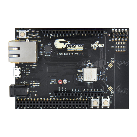
16. External JTAG Header (J3) 17. Arduino Header (J10) 18. Arduino Header (J12) 19. External PHY chip(U12) – BCM5241 20. External ADC Chip (U3) SD Connector/slot (J7) Figure 1-2. CYW943907AEVAL1F Evaluation Board CYW943907AEVAL1F Evaluation Kit User Guide, Doc. No. 002-18703 Rev. **... -
Page 9: Wiced Studio Development System Overview
Figure 1-3. CYW943907AEVAL1F Evaluation Board (Back View) 1.3 WICED Studio Development System Overview WICED Studio 5.0 (or later) supports application development using the WICED Evaluation Board (CYW943907AEVAL1F EVK). Tabs and their location in the WICED IDE are as shown in Figure 1-4. -
Page 10: Wiced Studio Code Examples
For more details on the WICED software stack and APIs, review the Application notes and documents available in the doc folder <WICED SDK installation folder>/WICED-Studio-5.0/43xxx_Wi- Fi/doc. WICED-QSG204 available in the same path is a good document to start with. CYW943907AEVAL1F Evaluation Kit User Guide, Doc. No. 002-18703 Rev. **... - Page 11 Introduction Figure 1-5. Filter for Wi-Fi Code Example in WICED Studio Figure 1-6. Code Examples under apps Category CYW943907AEVAL1F Evaluation Kit User Guide, Doc. No. 002-18703 Rev. **...
-
Page 12: Kit Code Examples
IoT device for your design, and quickly and effectively integrate the device into your design. Cypress provides customer access to a wide range of information, including technical documentation, schematic diagrams, product bill of materials, PCB layout information, and software updates. Customers can acquire technical documentation and software from the Cypress Support Community website (https://community.cypress.com). -
Page 13: Document Conventions
Power-on-Reset Power Management Unit VTRIM Voltage Trimming Low Power Oscillator GPIO General Purpose Input Output UART Universal Asynchronous Receiver/Transmitter Amazon Web Services Integrated Development Environment WLAN Wireless Local Area Network CYW943907AEVAL1F Evaluation Kit User Guide, Doc. No. 002-18703 Rev. **... -
Page 14: Software Installation
2. Software Installation This chapter describes the steps to install the software tools and packages on a PC for using the CYW943907AEVAL1F EVK. This includes the WICED IDE in which the projects will be built and used for programming. 2.1 Before You Begin All Cypress software installations require administrator privileges. - Page 15 5. Locate the WICED Wi-Fi-SDK directory in your PC. The default location is C:\Users\<user name>\Documents\WICED-Studio-5.0\43xxx_Wi-Fi, as shown in Figure 2-1. However, it may be in a different location depending on the path you choose when installing WICED Studio. Figure 2-1. WICED SDK Directory CYW943907AEVAL1F Evaluation Kit User Guide, Doc. No. 002-18703 Rev. **...
- Page 16 After unzipping, if the projects are not visible in WICED Studio 5.0 (or later), then right-click the top most folder (43xxx_Wi-Fi) and click Refresh, as shown in Figure 2-3. CYW943907AEVAL1F Evaluation Kit User Guide, Doc. No. 002-18703 Rev. **...
- Page 17 Software Installation Figure 2-3. Refresh Top Folder CYW943907AEVAL1F Evaluation Kit User Guide, Doc. No. 002-18703 Rev. **...
-
Page 18: Kit Operation
3. Kit Operation This chapter introduces you to the CYW943907AEVAL1F EVK and the features that will be used as part of Kit operation. Features such as Wi-Fi connection and programming/debugging are discussed in this chapter. The chapter also describes the USB-UART that can be used to communicate with the CYW43907 device on this EVK. -
Page 19: Cyw943907Aeval1F Kit Connection
When powered from USB, there are two logical USB devices: a USB-JTAG device and a USB- UART device. Drivers for the CYW943907AEVAL1F EVK are automatically installed during the WICED SDK installation process. When you connect the kit for first time to your PC, it will initiate the driver search as shown Figure 3-2. -
Page 20: Troubleshooting
If an error occurred during the automatic driver installation process, the driver may be manually installed from the following directory: <WICED-SDK>\Drivers\Windows\wiced_uart. If the CYW943907AEVAL1F EVK does not appear in the Device Manager, verify that the +3V3 LED is turned ON and check the USB cable. -
Page 21: Building, Programming, And Debugging Cyw943907Aeval1F Evk
To build and program a project for CYW943907AEVAL1F EVK, perform the following steps: 1. To open the WICED IDE on Windows PC, go to Start > All Programs > Cypress > WICED-Studio. 2. Select 43xxx_Wi-Fi in the WICED Target selector drop-down box as shown in . - Page 22 It is recommended to do Make clean when any new files are added or removed to the corresponding Target. Note: Ensure that you have connected CYW943907AEVAL1F EVK to the same PC via USB prior to executing the build target.
- Page 23 Figure 1-1) on the CYW943907AEVAL1F EVK to view the application start- up messages. 8. The output of the Terminal Emulation program should be similar to what is shown in Figure 3-6. CYW943907AEVAL1F Evaluation Kit User Guide, Doc. No. 002-18703 Rev. **...
-
Page 24: Troubleshooting
Kit Operation Figure 3-6. Console Output 3.4.2 Troubleshooting If a download_dct error message is displayed despite connecting the board, follow the steps outlined in this post. CYW943907AEVAL1F Evaluation Kit User Guide, Doc. No. 002-18703 Rev. **... -
Page 25: Debugging A Project Using Breakpoints
Kit Operation 3.4.3 Debugging a Project using Breakpoints After programming a project, it is possible to debug it in CYW943907AEVAL1F EVK using the built in debugger. Note that the scan example used in Building and Programming a Project for CYW943907AEVAL1F in WICED Studio IDE section is also used here. - Page 26 6. To terminate the Debugging session, click Run > Terminate, or click on the red Square icon. Once you terminate the session, click on “C/C++” in the upper right corner to return to the C/C++ perspective. CYW943907AEVAL1F Evaluation Kit User Guide, Doc. No. 002-18703 Rev. **...
- Page 27 8. Right-click the desired breakpoint checkbox and click Breakpoint Properties…. Click the last_built.elf check box, as shown in Figure 3-10. The check mark appears before the actual breakpoint indicating its association with the current execution. CYW943907AEVAL1F Evaluation Kit User Guide, Doc. No. 002-18703 Rev. **...
- Page 28 Kit Operation Figure 3-9. Show Breakpoints Icon Figure 3-10. Enabling Breakpoint for Current Execution CYW943907AEVAL1F Evaluation Kit User Guide, Doc. No. 002-18703 Rev. **...
-
Page 29: Hardware
4. Hardware This chapter describes the CYW943907AEVAL1F EVK hardware and its different blocks, such as Bootstrap, reset control, Arduino-compatible headers, and module connectors. The schematic is available at the following location after installing the software from Software Installation. <WICED_SDK_Directory>\43xx_Wifi\platforms\CYW943907AEVAL1F\schematics. 4.1 Bootstrap... -
Page 30: User Switches
WICED for these LEDs. Table 4-3. User LED Available on the Board Switch CYW43907 Pin Name WICED_ENUM_ID Alternate Enumeration in WICED LED_1 PWM_3 WICED_GPIO_16 WICED_LED1 LED_2 GPIO_9 WICED_GPIO_5 WICED_LED2 CYW943907AEVAL1F Evaluation Kit User Guide, Doc. No. 002-18703 Rev. **... -
Page 31: Reset Control
VDDIO have reached 90% of their final values. To ensure proper boot up, the RC delay circuit for HIB_REG_ON_IN is essential as shown in Figure 4-4. Figure 4-3. Reset Circuit Diagram Figure 4-4. HIB_REG_ON_IN RC Delay Circuit CYW943907AEVAL1F Evaluation Kit User Guide, Doc. No. 002-18703 Rev. **... -
Page 32: Ethernet
TXD2 RMII_G_TXD3 MII_TXD3 TXD3 RMII_G_RXD0 MII_RXD0 RXD0/PHYAD0 RMII_G_RXD1 MII_RXD1 RXD1/ANEN_L RMII_G_RXD2 MII_RXD2 RXD2/F100 RMII_G_RXD3 MII_RXD3 RXD3/ISOLATE RMII_MDIO MII_MDIO MDIO RMII_MDC MII_MDC RMII_G_TXEN MII_TXEN TXEN RMII_G_RXDV MII_RXDV_CRS_DV RXDV PWM_2 PWM_2 RESET_L CYW943907AEVAL1F Evaluation Kit User Guide, Doc. No. 002-18703 Rev. **... - Page 33 Hardware Figure 4-5. Ethernet MAC Controller to External PHY Connection CYW943907AEVAL1F Evaluation Kit User Guide, Doc. No. 002-18703 Rev. **...
-
Page 34: Micro Sd Connector/Slot
SL. NO CYW43907 Based SIP Pin Name Micro SD Connector/Slot Name SDIO_DATA_0 DAT0 SDIO_DATA_1 DAT1 SDIO_DATA_2 DAT2 SDIO_DATA_3 CD/DAT3 SDIO_CMD SDIO_CLK PWM_0 DETECT Figure 4-6. Micro SD Connector Circuit Diagram CYW943907AEVAL1F Evaluation Kit User Guide, Doc. No. 002-18703 Rev. **... -
Page 35: Jtag Connector
External JTAG device. Figure 4-8 shows the connection between Olimex and the CYW943907AEVAL1F EVK. Figure 4-7. External JTAG Connector Circuit Diagram CYW943907AEVAL1F Evaluation Kit User Guide, Doc. No. 002-18703 Rev. **... -
Page 36: Connectors
4.8 Connectors 4.8.1 WICED Header J6 is the WICED header available on CYW943907AEVAL1F EVK. This is a 44-pin header containing I2C, SDIO, UART, SPI, PWM lines, and I/Os. Note that some signals are shared with Arduino header (UART0 Tx/Rx) and On-board Programmer/debugger chip (UART1). - Page 37 WICED_GPIO_47 J6.35 SDIO_DATA_2 WICED_GPIO_46 J6.36 RF_SW_CTRL_6_UART1_RXD WICED_PERIPHERAL_PIN_1 WICED_UART_1 J6.37 UART1_TXD WICED_PERIPHERAL_PIN_2 WICED_UART_1 J6.38 RF_SW_CTRL_8_UART2_RXD WICED_PERIPHERAL_PIN_7 WICED_UART_3 J6.39 UART2_TXD WICED_PERIPHERAL_PIN_8 WICED_UART_3 J6.40 HIB_WAKE J6.41 HIB_LPO_SEL J6.42 HIB_REG_ON_IN J6.43 USB2_DN J6.44 USB2_DP CYW943907AEVAL1F Evaluation Kit User Guide, Doc. No. 002-18703 Rev. **...
-
Page 38: Arduino-Compatible Headers
Hardware 4.8.2 Arduino-Compatible Headers J9, J13, J12 and J10 are the Arduino headers available in the CYW943907AEVAL1F EVK. Table 4-8 shows the pinout of the Arduino Header. Note the following points while connecting an Arduino shield to the board: ... -
Page 39: Uart Port Configuration On Cyw943907Aeval1F Kit
Figure 4-9. Table 4-9. External ADC Connection I2C Line CYW43907 Pin Name WICED Enumeration Alternate Enumeration I2C_0_SDA WICED_GPIO_48 WICED_I2C_1 I2C_0_SCL WICED_GPIO_49 WICED_I2C_1 Figure 4-9. External ADC Circuit Diagram CYW943907AEVAL1F Evaluation Kit User Guide, Doc. No. 002-18703 Rev. **... -
Page 40: Pwm
There are six dedicated PWM outputs available on CYW43907. These PWMs can be multiplexed onto different pins. You can find their definitions in platforms/CYW943907AEVAL1F/platform.c inside WICED Studio. The PWMs can be re-assigned to other pins by changing the first argument of the platform_pwm_t platform_pwm_peripherals structure in platform.c... - Page 41 Header Name PIN_GPIO_7 (DEFAULT) J10.4.4 Arduino D3 PIN_GPIO_1 J10.1 Arduino D0 PIN_GPIO_9 J12.9 Arduino SCK PIN_GPIO_11 J12.3 Arduino D10 PIN_GPIO_13 J10.3 Arduino D2 PIN_GPIO_15 J10.7 Arduino D6 PIN_PWM_5 CYW943907AEVAL1F Evaluation Kit User Guide, Doc. No. 002-18703 Rev. **...
-
Page 42: Code Examples
5. Code Examples This chapter demonstrates the functionality of CYW43907 devices using the CYW943907AEVAL1F EVK code examples. Download and extract the zip file from the CYW943907AEVAL1F EVK web page as specified in Install Software section. The code examples once un-zipped can be viewed in WICED Studio 5.0 (or later). In addition to the added examples there are already many apps (snip.gpio, test.console, and so on) that are available in... -
Page 43: Verify Output
5.3 Config_join_ping 5.3.1 Project Description The config_join_ping project demonstrates connectivity between CYW943907AEVAL1F EVK and a Wi-Fi access point. This example is based on existing examples available in the WICED Studio 5.0 (or later) SDK namely, apps/snip/scan, apps/snip/dct_read_write and test/console. On startup, this application shows a console through which the user can enter commands to scan, configure, join, and ping Wi-Fi access points. -
Page 44: Flow Chart
Figure 5-1. config_join_ping Flow Chart System Initialized Initialize Command Console to STDIO UART Add New Commands to the Console Commands List Wait for Command from Console Execute Corresponding Function from Command Table CYW943907AEVAL1F Evaluation Kit User Guide, Doc. No. 002-18703 Rev. **... -
Page 45: Verify Output
Type the command help to see the list of available commands as shown in Figure 5-2. Figure 5-2. Initial Console Output Type the command scan to find the list of available Wi-Fi access points as shown in Figure 5-3. CYW943907AEVAL1F Evaluation Kit User Guide, Doc. No. 002-18703 Rev. **... - Page 46 DCT. Ping the Access point (usually 192.168.1.1) or 8.8.8.8 (IP address of Google, if your AP is connected to internet) and check if the network is up and responding. The message “Ping Reply 11ms” is displayed as shown in Figure 5-4. Figure 5-4. Join and Ping CYW943907AEVAL1F Evaluation Kit User Guide, Doc. No. 002-18703 Rev. **...
-
Page 47: Adc_Measure
VCC and ADC channel 2 (to simulate full scale) or a wire between GND and ADC channel 1 (to simulate zero scale). Alternately, you can connect an adjustable DC power supply to ADC channel Figure 5-5. Potentiometer Connection CYW943907AEVAL1F Evaluation Kit User Guide, Doc. No. 002-18703 Rev. **... -
Page 48: Flow Chart
Use the received time from NTP and build Use 00:00:00 UTC time and build the web the web page page Add 1 sec timed event (for measuring ADC output and updating web page) and start web page CYW943907AEVAL1F Evaluation Kit User Guide, Doc. No. 002-18703 Rev. **... -
Page 49: Access Point Credentials
5-8. It should be noted that the PC and CYW943907AEVAL1F EVK should be connected to the same access point. Rotate the potentiometer and verify that the value shown on web page changes accordingly. One easy way to validate the correct functioning is to rotate the potentiometer to one of the extremes and observe if the full scale value appears. -
Page 50: Publish_Subscribe_Aws
WPA2 security. The Wi-Fi access point must have access to the internet to connect with AWS. CYW943907AEVAL1F Evaluation Kit User Guide, Doc. No. 002-18703 Rev. **... -
Page 51: Hardware Connections
Bring-up WLAN Interface and Connect to MQTT Broker Error? Open Connection, Subscribe to messages and Publish messages when switch is pressed Error Publishing Exceed Retry Count? Throw Error Message and Exit CYW943907AEVAL1F Evaluation Kit User Guide, Doc. No. 002-18703 Rev. **... -
Page 52: Verify Output
AWS to create the same. 3. In the created Thing window, click the left arrow to navigate back to the AWS IoT Console window. CYW943907AEVAL1F Evaluation Kit User Guide, Doc. No. 002-18703 Rev. **... - Page 53 Select the check box Allow Effect and then click the Create button as shown in Figure 5-10. 6. In the created policy window, click to navigate back to the AWS IoT Console window. Figure 5-10. Create policy CYW943907AEVAL1F Evaluation Kit User Guide, Doc. No. 002-18703 Rev. **...
- Page 54 <WICED-SDK>\43xxx_Wi- Fi\resources\apps\aws_iot\. 4. Click the Activate button and then click the Attach a policy button as shown in Figure 5-12. The Add authorization to certificate window appears (see Figure 5-13). CYW943907AEVAL1F Evaluation Kit User Guide, Doc. No. 002-18703 Rev. **...
- Page 55 Figure 5-12. Activate and Attach policy 5. Select the check box next to the policy you want to choose and then click the Attach policy button, as shown in Figure 5-13. CYW943907AEVAL1F Evaluation Kit User Guide, Doc. No. 002-18703 Rev. **...
- Page 56 11. Click the specific Thing. The Thing ARN window appears. 12. In left navigation pane, choose Interact. 13. Copy the Endpoint from the HTTPS tab as shown in Figure 5-14. CYW943907AEVAL1F Evaluation Kit User Guide, Doc. No. 002-18703 Rev. **...
- Page 57 AWS console itself. In the AWS IoT Console window, go to Dashboard > Messages published and you should be able to see the number of messages exchanged as shown in Figure 5-15. CYW943907AEVAL1F Evaluation Kit User Guide, Doc. No. 002-18703 Rev. **...
- Page 58 Code Examples Figure 5-15. Publish_Subscribe Output Figure 5-16. Messages Published CYW943907AEVAL1F Evaluation Kit User Guide, Doc. No. 002-18703 Rev. **...
-
Page 59: Revision History
Document Revision History Document Title: CYW943907AEVAL1F Evaluation Kit User Guide Document Number: 002-18703 Origin of Revision Issue Date Description of Change Change 06/22/2017 KAVS Initial version of the kit guide. CYW943907AEVAL1F Evaluation Kit User Guide, Doc. No. 002-18703 Rev. **...
Need help?
Do you have a question about the CYW943907AEVAL1F and is the answer not in the manual?
Questions and answers