
Related Manuals for Cypress CYW920735Q60EVB-01


Summary of Contents for Cypress CYW920735Q60EVB-01
- Page 1 WICED Studio CYW920735Q60EVB-01 Evaluation Kit User Guide Associated Part Family: CYW20735 Doc. No.: 002-23764 Rev. ** Cypress Semiconductor 198 Champion Court San Jose, CA 95134-1709 www.cypress.com...
-
Page 2: Table Of Contents
2.6.7.3 View Traces Using the BTSpy Windows Application ............. 21 Kit Operation ................................23 Theory of Operation ............................23 Jumpers ................................28 Buttons and Switches ............................30 Arduino-Compatible Headers ........................... 31 CYW920735Q60EVB-01 Evaluation Kit User Guide Doc. No.: 002-23764 Rev. **... - Page 3 Thermistor ................................ 45 Motion Sensor ..............................45 LED .................................. 46 Analog Mic ................................ 46 5.10 Push Buttons ..............................47 Appendix A. CYW20735 Device IO Mapping ......................48 Document Revision History ............................. 51 CYW920735Q60EVB-01 Evaluation Kit User Guide Doc. No.: 002-23764 Rev. **...
-
Page 4: Safety Information
Handling Boards CYW920735Q60EVB-01 boards are sensitive to ESD. Hold the board only by its edges. After removing the board from its box, place it on a grounded, static-free surface. Use a conductive foam pad if available. Do not slide the board over any surface. -
Page 5: Introduction
CYW20735B1, dual-mode Bluetooth 5.0 (BLE and BR) wireless MCU. The CYW920735Q60EVB-01 EVB can be used with WICED™ Studio to develop and debug your CYW20735 project. The CYW920735Q60EVB-01 EVB offers footprint-compatibility with Arduino shields. In addition, the kit features an onboard programmer and USB-UART chip. -
Page 6: Cyw920735Q60Evb-01 Board Details
The WICED Studio Development System comprises a software development kit (SDK) along with the Eclipse integrated development environment (IDE) to enable development of projects with WICED evaluation boards. The CYW920735Q60EVB-01 board and WICED Studio can be used for feature evaluation, debugging, and developing Bluetooth applications based on the CYW20735 device. -
Page 7: Getting Started
Cypress applications engineers and experienced peers. 1.6 Additional Learning Resources Visit the http://www.cypress.com/documentation/development-kitsboards/cyw920735q60evb-01-evaluation-kit webpage for additional learning resources including datasheets and application notes. -
Page 8: Acronyms
Printed Circuit Board PUART Peripheral UART Pulse Width Modulation Radio Frequency Software Development Kit Special Interest Group System-On-Chip Serial Peripheral Interface Serial Wire Debug UART Universal Asynchronous Receiver/Transmitter Universal Serial Bus CYW920735Q60EVB-01 Evaluation Kit User Guide Doc. No.: 002-23764 Rev. **... - Page 9 Introduction Acronym Definition Voltage Drain Drain WICED Wireless Internet Connectivity for Embedded Devices XTAL Crystal Oscillator Table 1-2. List of Acronyms used in this Document CYW920735Q60EVB-01 Evaluation Kit User Guide Doc. No.: 002-23764 Rev. **...
-
Page 10: Wiced Studio
2.1 Before You Begin All Cypress software installations require administrator privileges. Make sure that you have the required privileges on the system for successful installation. Before you install the kit software, close any other Cypress software that is currently running. -
Page 11: Install Wiced Studio
If this command returns “1.6”, then you will need to fix the symbolic link using the following commands: rm -f /usr/bin/java ln -s /System/Library/Frameworks/JavaVM.framework/Versions/Current/Commands/java /usr/bin/java CYW920735Q60EVB-01 Evaluation Kit User Guide Doc. No.: 002-23764 Rev. **... -
Page 12: Connect The Wiced Evaluation Board
D6 (Green) indicates that VDD3P3 (3.3 V) power is ON D7 (variable color) indicates HCI UART activity D11 (variable color) indicates peripheral UART activity D1 (Yellow) and D2 (Red) are generic user LEDs controlled by GPIOs CYW920735Q60EVB-01 Evaluation Kit User Guide Doc. No.: 002-23764 Rev. **... -
Page 13: Verify Driver Installation
Note: On OS X versions 10.10 or earlier, the Apple version of the FTDI driver that ships with the OS has known issues. Follow the instructions here and update to a specific version. CYW920735Q60EVB-01 Evaluation Kit User Guide Doc. No.: 002-23764 Rev. **... -
Page 14: Using The Wiced Studio Ide
Make Target Window - Create and edit Make Targets for the platform to build your application or project. Console Window - View Build messages in the Console window. Help Window - Access Help that contains instructions on building and downloading applications. Figure 2-3. WICED Studio IDE CYW920735Q60EVB-01 Evaluation Kit User Guide Doc. No.: 002-23764 Rev. **... -
Page 15: Wiced Studio Sdk Directory Structure
WICED BT API usage for host MCU apps. Located within each subdirectory in the apps folder is a README.txt that lists and summarizes the applications located within the folder: CYW920735Q60EVB-01 Evaluation Kit User Guide Doc. No.: 002-23764 Rev. **... -
Page 16: Build And Load A Sample Application
The Make Target pane contains make targets that are preconfigured for sample applications that run on CYW920735Q60EVB-01 evaluation boards. The hello_sensor sample demonstrates basic LE sensor functionality. The source file hello_sensor.c contains information on how to exercise the application with the Hello Client host peer application. - Page 17 Note: The warnings ‘section '.XXX' mentioned in a -j option, but not found in any input file’ above are not problems; this is only an indication that the application did not use any data in the mentioned sections. CYW920735Q60EVB-01 Evaluation Kit User Guide Doc. No.: 002-23764 Rev. **...
-
Page 18: Hello Client Peer Application
(*) characters, in which case WICED Studio will generate random hexadecimal values for the asterisks using the host PC MAC address, so that the random digits will always be the same from a single PC, but different for other PCs. CYW920735Q60EVB-01 Evaluation Kit User Guide Doc. No.: 002-23764 Rev. **... -
Page 19: Testing The Hello Sensor Application
Press button SW3 on the WICED board (see Figure 3-3). The Hello X message is displayed in the Value field. Each time the button is pressed, the message number increments. CYW920735Q60EVB-01 Evaluation Kit User Guide Doc. No.: 002-23764 Rev. **... -
Page 20: Hello Configuration Characteristic
PUART by default. The other options (HCI_UART and WICED_UART) are provided in the source file as comments. You can comment out the PUART lines and uncomment either the HCI_UART or WICED_UART line if you want to try one of the other options. CYW920735Q60EVB-01 Evaluation Kit User Guide Doc. No.: 002-23764 Rev. **... -
Page 21: View Traces Using A Terminal Emulation Program
API for routing traces to the HCI UART port, and in any calls to the wiced_hal_puart_set_baudrate() API overriding the default rate for routing traces to the PUART port. CYW920735Q60EVB-01 Evaluation Kit User Guide Doc. No.: 002-23764 Rev. **... - Page 22 In the ClientControl utility, open the HCI UART COM port by clicking the Open Port button. Press Reset (SW2) on the WICED evaluation board to reset the kit and view trace messages in the BTSpy window. CYW920735Q60EVB-01 Evaluation Kit User Guide Doc. No.: 002-23764 Rev. **...
-
Page 23: Kit Operation
Development System for Bluetooth Classic (aka BR - Basic Rate) and Low Energy (LE) devices. This chapter introduces you to the CYW920735Q60EVB-01 EVB and the features that will be used as part of kit operation. This chapter also discusses features such as the Bluetooth connection and programming/debugging as well as the USB- UART bridge device that can be used to communicate with the CYW20735-B1 device on this EVB. - Page 24 Kit Operation Figure 3-2 illustrates the block diagram of the CYW920735Q60EVB-01 EVB. This board contains a CYW20735-B1 Bluetooth device and a USB-Serial interface/debugger. The kit features Arduino form-factor compatible headers, which enables Arduino shields to be plugged on top, extending its capabilities. It also features one user switch, one reset switch, one recovery switch, two user LEDs, a thermistor, and a motion sensor.
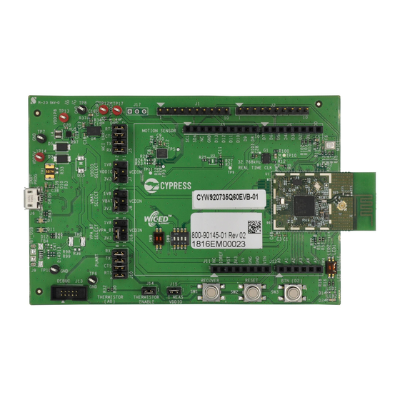
- Page 25 Kit Operation Figure 3-3 Figure 3-4 show the markup of the CYW920735Q60EVB-01 board. See the list below for a description of the numbered items. Figure 3-3. CYW920735Q60EVB-01 Evaluation Board CYW920735Q60EVB-01 Evaluation Kit User Guide Doc. No.: 002-23764 Rev. **...
- Page 26 13. Recovery Button (SW1): This button is used to put the device in recovery mode. To put the device in recovery mode, press and hold the recovery button, press and release the reset button, then release the recovery button. CYW920735Q60EVB-01 Evaluation Kit User Guide Doc. No.: 002-23764 Rev. **...
- Page 27 USB Slave. 36. PUART Voltage Level translator (U9): This voltage level translator IC allows the interoperability of devices with different high-level voltage and low-level voltage for input and output operations. CYW920735Q60EVB-01 Evaluation Kit User Guide Doc. No.: 002-23764 Rev. **...
-
Page 28: Jumpers
CYW20735 device. Also, use this 3 and 4 Open jumper to measure the current consumption of VBAT when using the coin cell supply (VCOIN). Table 3-3. Jumper J8 Pin Configurations CYW920735Q60EVB-01 Evaluation Kit User Guide Doc. No.: 002-23764 Rev. **... - Page 29 IO Domain (VDDIO) of the 1 and 2 Shorted LHL_VDDIO, BT_VDDIO CYW20735. Also, use this jumper to measure the current consumption of the IO Domain. Table 3-6. Jumper J15 Pin Configurations CYW920735Q60EVB-01 Evaluation Kit User Guide Doc. No.: 002-23764 Rev. **...
-
Page 30: Buttons And Switches
The DIP switch SW4 enables or disables the two onboard user LEDs. By default, both LED1 and LED2 are enabled. Connection on CYW20735 Description DIP SW4 Default State Device Enables LED1 Enables LED2 Table 3-9. SW4 DIP Switches Configuration CYW920735Q60EVB-01 Evaluation Kit User Guide Doc. No.: 002-23764 Rev. **... -
Page 31: Arduino-Compatible Headers
Analog mic, LEDs, Real Time clock, 9-axis Motion sensor and Thermistor. Pole 2, 3 and 4 of the SW8 allows the user to connect particular pins to the recovery button. The selections for poles 2, 3, and 4 should not be changed for the CYW920735Q60EVB-01 EVB – they are only used for other variations of the base board. Connection on CYW20735... - Page 32 WICED_P08 General purpose GPIO WICED_P09 General purpose GPIO WICED_P10 General purpose GPIO WICED_P11 General purpose GPIO WICED_P12 General purpose GPIO WICED_P13 General purpose GPIO Table 3-15. Header J12 Pin Configurations CYW920735Q60EVB-01 Evaluation Kit User Guide Doc. No.: 002-23764 Rev. **...
-
Page 33: Other Headers
SPI (Slave Select) External Flash Memory RSVD10 SF_SPI_CLK SPI (Clock) External Flash Memory Table 3-17. Header J2 Pin description J13 is a 10-pin debugger header to debug the CYW920735Q60EVB-01 using SWD. Connection to Header Connection on CYW20735 WICED Enum Name Description Header J13... -
Page 34: Usb Serial Interface Chip
Test point for VDD5V TP17 Test point for VCOIN Table 3-19. Test points for power domains available in CYW920735Q60EVB-01 J17 is a 3-pin test-point for testing purposes of the 9-axis motion sensor (U2) interrupts. Test-Point J17 Connection to Header pin... -
Page 35: Current Measurement
WICED Studio supports multiple ARM-JTAG adapters for debugging Bluetooth products like the CYW20735. Debugging is possible on CYW920735Q60EVB-01 through SWD (Serial Wire Debug) signals. SWD is a two-wire interface that uses SWDIO (SWD Input Output) and SWDCK (Serial Wire Clock) for debugging the device. These two lines can be brought out to any of the LHL GPIOs on the CYW20735. -
Page 36: Code Examples
This project demonstrates the ADC and BLE capability of the CYW20735 device. A negative temperature coefficient type of thermistor is used to measure ambient temperature. The thermistor present on the CYW920735Q60EVB-01 Evaluation board is PN NCU15W104F60RC from Murata. It is a 100 KΩ thermistor at 25 °C with 1% accuracy. The thermistor is connected to GPIO P8 on the CYW20735 device. -
Page 37: Flow Chart
BT Stack Initialization Initialize HAL Initialize Timer to Read ADC Calculate Temperature in Samples Periodically Celsius GATT DB Initialization Start Advertising Device Connected? Send Notifications Periodically Figure 4-1. thermistor_app Flowchart CYW920735Q60EVB-01 Evaluation Kit User Guide Doc. No.: 002-23764 Rev. **... -
Page 38: Verify Output
If no client is connected, you will see a “Connection is not up” message instead. Figure 4-3. env_sensing_temp output CYW920735Q60EVB-01 Evaluation Kit User Guide Doc. No.: 002-23764 Rev. **... -
Page 39: Hardware
5.1 Carrier Module The base board of the CYW920735Q60EVB-01 kit is designed to be modular so that many devices can be used with the same base board. The actual device (CYW20735 in this case) is on the carrier module. The carrier module interface is a generic interface that can be used across may devices. -
Page 40: Base Board
SCL and SDA. Please note that SW8.1(VDDP) should be turned on for any I2C devices to be connected because the pull-up voltages for SCL and SDA are supplied from VDDP. CYW920735Q60EVB-01 Evaluation Kit User Guide Doc. No.: 002-23764 Rev. **... - Page 41 Hardware Figure 5-3. 5 V Power Supply from USB Figure 5-4. 3.3 V Regulator Circuit CYW920735Q60EVB-01 Evaluation Kit User Guide Doc. No.: 002-23764 Rev. **...
- Page 42 Hardware Figure 5-5. 1.8 V Regulator Circuit Figure 5-6. Jumper J7 for VDDIO Selection Figure 5-7. Jumper J8 for VBAT Selection CYW920735Q60EVB-01 Evaluation Kit User Guide Doc. No.: 002-23764 Rev. **...
- Page 43 Hardware Figure 5-8. Jumper J16 for VPA_BT Selection Figure 5-9. DIP Switch SW8 functionality CYW920735Q60EVB-01 Evaluation Kit User Guide Doc. No.: 002-23764 Rev. **...
-
Page 44: Reset
SW2 Alternately in this case, the device can be reset by driving the Arduino header reset pin low allowing for an external reset source. Figure 5-11. Reset to Arduino Header CYW920735Q60EVB-01 Evaluation Kit User Guide Doc. No.: 002-23764 Rev. **... -
Page 45: Thermistor
Figure 5-12. Thermistor Circuit 5.7 Motion Sensor The CYW920735Q60EVB-01 has an onboard 9-axis motion sensor (LSM9DS1). It has three acceleration channels, three angular rate channels, and three magnetic field channels. The CYW20735 device communicates with this sensor over I The I C address to access the accelerometer and gyroscope is 0xD4 and to access the magnetometer, address is 0x38. -
Page 46: Led
CYW20735. Typical MIC_BIAS output voltage is 2.1V when supply voltage(MIC_AVDD) is 2.5V. Please refer to the datasheet for more details on ADC Electrical Specifications. In CYW920735Q60EVB-01 kit, the MIC_AVDD is powered by VDDIO which can have either 1.8V or 3.3V supply voltage. The R11 resistor’s position will determine the supply voltage to MIC1. -
Page 47: Push Buttons
Hardware Figure 5-15. Analog Mic 5.10 Push Buttons The CYW920735Q60EVB-01 has a reset button, recovery button, and a user button. See the RESET section for details on the Reset button. See the Build and Load a Sample Application section for details on using the recovery button during kit programming. -
Page 48: Appendix A. Cyw20735 Device Io Mapping
Headers) Debugger) J4.3 (ON J13.4 (OFF WICED_P03 SW9.1 (DIP Switch) for Arduino ROW3/DMIC_DATA/D5 Headers) Debugger) WICED_P04 ROW4/PCM_OUT/I2S_D0/D6 J4.2 RSVD6 Reserved J2.6 GND_87 Ground Ground WICED_P05 ROW5/PCM_IN/I2S_DI/D7 J4.1 WICED_P06 ROW6/SPI_MOSI/D11 J3.7 CYW920735Q60EVB-01 Evaluation Kit User Guide Doc. No.: 002-23764 Rev. **... - Page 49 ON for Recovery Motion Button) J3.2 sensor WICED_P26 LED2/SPI_INT SW4.2 DIP Switch J1.2 WICED_P27 LED1/SF_WP SW4.1 DIP Switch J1.1 J13.4, J4.7, WICED_P32 PUART_TXD/D1 J10.5 J13.2, J4.8, WICED_P29 PUART_RXD/D0 J10.7 GND_120 Ground Ground CYW920735Q60EVB-01 Evaluation Kit User Guide Doc. No.: 002-23764 Rev. **...
- Page 50 Reserved J2.3 RSVD2 Reserved J2.2 RSVD1 Reserved J2.1 GND_125 Ground Ground STATUS J1.5 TX_REQ/BT_SECI_OUT J1.6 TX_CONF/BT_SECI_IN J1.7 BT_HOST_WAKE HOST_WAKE J1.4 BT_DEV_WAKE J1.3 Table A-1. Carrier Module Interface and Pin Connections CYW920735Q60EVB-01 Evaluation Kit User Guide Doc. No.: 002-23764 Rev. **...
-
Page 51: Document Revision History
Document Revision History Document Title: CYW920735Q60EVB-01 Evaluation Kit User Guide Document Number: 002-23764 Revision Origin of Issue Date Description of Change Change 6168755 SIRK 05/17/2018 Initial release. CYW920735Q60EVB-01 Evaluation Kit User Guide Doc. No.: 002-23764 Rev. **... - Page 52 (“Unintended Uses”). A critical component is any component of a device or system whose failure to perform can be reasonably expected to cause the failure of the device or system, or to affect its safety or effectiveness. Cypress is not liable, in whole or in part, and you shall and hereby do release Cypress from any claim, damage, or other liability arising from or related to all Unintended Uses of Cypress products.
- Page 53 Mouser Electronics Authorized Distributor Click to View Pricing, Inventory, Delivery & Lifecycle Information: Cypress Semiconductor CYW920735Q60EVB-01...
Need help?
Do you have a question about the CYW920735Q60EVB-01 and is the answer not in the manual?
Questions and answers