Table of Contents
Advertisement
Quick Links
Advertisement
Table of Contents

Related Manuals for Cypress CY8CKIT-037


Summary of Contents for Cypress CY8CKIT-037
- Page 1 CY8CKIT-037 PSoC 4 Motor Control Evaluation Kit ® Guide Doc. No. 001-92562 Rev.*A Cypress Semiconductor 198 Champion Court San Jose, CA 95134 USA www.cypress.com ® CY8CKIT-037 PSoC 4 Motor Control Evaluation Kit Guide, Doc. No. 001-92562 Rev.*A...
- Page 2 Uses”). A critical component is any component of a device or system whose failure to perform can be reasonably expected to cause the failure of the device or system, or to affect its safety or effectiveness. Cypress is not liable, in whole or in part, and you shall and hereby do release Cypress from any claim, damage, or other liability arising from or related to all Unintended Uses of Cypress products.
-
Page 3: Table Of Contents
Kit Installation ..............................9 Prerequisite Software ............................9 Install Kit Software ..............................9 Uninstall Software ..............................12 Kit Overview ............................... 13 CY8CKIT-037 Evaluation Kit Overview ....................... 13 Kit Operation and Configuration Guide ........................ 13 3.2.1 DC Power Supply Connector ........................13 3.2.2 Motor Winding Connectors ........................ - Page 4 Reading the Motor Speed Using BCP Commands ................. 78 Appendix A: Board Schematics, Board Layout, and BOM ..................80 A.1 Board Schematics ..............................80 A.2 Board Layout ................................87 A.3 Bill of Materials ................................ 89 ® CY8CKIT-037 PSoC 4 Motor Control Evaluation Kit Guide, Doc. No. 001-92562 Rev.*A...
-
Page 5: Safety Information
If such interference is detected, suitable mitigating measures should be taken. The CY8CKIT-037, as shipped from the factory, has been verified to meet with the requirements of CE as a Class A product. -
Page 6: General Safety Instructions
Handling Boards CY8CKIT-037 boards are sensitive to ESD. Hold the board only by its edges. After removing the board from its box, place it on a grounded, static-free surface. Use a conductive foam pad if available. Do not slide the board over any surface. -
Page 7: Introduction
4 Motor Control Evaluation Kit (EVK). This kit enables engineers to evaluate Cypress's PSoC family of devices for motor control applications. Based on this kit, customers can create control solutions for three dominant motor types: permanent magnet synchronous motor (PMSM), stepper, and brushless DC (BLDC). -
Page 8: Additional Learning Resources
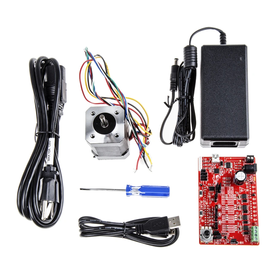
Introduction Figure 1-1. CY8CKIT-037 PSoC 4 Motor Control EVK Contents Visit www.cypress.com/shop for more information. Inspect the contents of the kit; if any parts are missing, contact your nearest Cypress sales office for help. 1.2 Additional Learning Resources Visit www.cypress.com for additional learning resources in the form of datasheets, technical reference manuals, and application notes. -
Page 9: Kit Installation
Figure 2-1. Available Formats for Downloading EVK Software CY8CKIT-037 CD ISO: This file is a complete package, stored in a CD-ROM image format, that you can use to create a CD or extract using ISO extraction programs, such as WinZip or WinRAR. The file can also be mounted like a virtual CD using virtual drive programs such as Virtual CloneDrive and MagicISO. - Page 10 Figure 2-2. Kit Installer Startup Screen Select the folder in which you want to install the CY8CKIT-037 kit-related files. Choose the directory and click Next. When you click Next button, the CY8CKIT-037 ISO installer automatically installs the required software, if it is not present on your computer.
- Page 11 Enter your contact information or select the option Continue without Contact Information. Click Finish to complete the CY8CKIT-037 kit installation. After the installation is complete, the kit contents are available at <Install_Directory>\CY8CKIT-037 Motor Control EVK\1.0. The default locations are as follows: ...
-
Page 12: Uninstall Software
Go to Start > All Programs > Cypress > Cypress Update Manager > Cypress Update Manager; click Uninstall for the appropriate software package. Select the “CY8CKIT-037 Motor Control EVK 1.0 Rev **” row and click Uninstall. In the Product Installation ... -
Page 13: Kit Overview
3.1 CY8CKIT-037 Evaluation Kit Overview The motor control system can be separated into two parts: the driver board and the controller board. The CY8CKIT-037 Motor Control EVK is the driver board, which contains the DC/DC power circuit, dual H-bridge circuit, motor current and bus voltage sampling and processing circuit, protection circuit, user configuration circuit, and connectors to the controller board. -
Page 14: Motor Winding Connectors
3 – HALL B Hall sensor B output – Green 4 – HALL C Hall sensor C output – White 5 – GND Hall sensor board ground – Black ® CY8CKIT-037 PSoC 4 Motor Control Evaluation Kit Guide, Doc. No. 001-92562 Rev.*A... -
Page 15: Connectors To Cy8Ckit-042 Board
The USB-to-UART bridge circuit on the EVK board and PC can be connected by USB cable through the J11 connector, Figure 3-6 shows. For schematic details of the USB-to-UART bridge circuit part, refer to USB-to-UART Bridge Controller Circuit. Figure 3-6. USB-to-UART Bridge Controller Circuit ® CY8CKIT-037 PSoC 4 Motor Control Evaluation Kit Guide, Doc. No. 001-92562 Rev.*A... -
Page 16: Kit Hardware Schematic Details
4. Kit Hardware Schematic Details 4.1 Block Diagram Overview Figure 4-1 illustrates the CY8CKIT-037 hardware block diagram. The major features are as follows: Input protection circuit DC/DC switching regulator MOSFET dual H-bridge and dual H-bridge PWM drivers ... -
Page 17: Input Protection Circuit
R2 divider with 10 kΩ and 2 kΩ will give exactly 1.225 at 7.35-V input. If the input goes below 7.35 V, LM5005 will be in an inactive state. ® CY8CKIT-037 PSoC 4 Motor Control Evaluation Kit Guide, Doc. No. 001-92562 Rev.*A... -
Page 18: Mosfet Dual H-Bridge And Dual H-Bridge Pwm Drivers
Considering the compatibility for different motor control types, the population of components J19, J20, and J21 needs to be adjusted to fit different motor type applications. Figure 4-5. MOSFET Dual H-Bridge ® CY8CKIT-037 PSoC 4 Motor Control Evaluation Kit Guide, Doc. No. 001-92562 Rev.*A... -
Page 19: Phase Current Detecting And Processing Circuit
IDAC. The comparator output is routed to the PWM kill terminal to shut down the PWM output, forcing the winding current to follow the IDAC current reference. ® CY8CKIT-037 PSoC 4 Motor Control Evaluation Kit Guide, Doc. No. 001-92562 Rev.*A... - Page 20 U7 amplifies and filters the sum of the currents. Its output is routed to the positive terminal of the internal LPComp to be compared with the overcurrent threshold set by the IDAC. Figure 4-8. Overcurrent Protection Circuit ® CY8CKIT-037 PSoC 4 Motor Control Evaluation Kit Guide, Doc. No. 001-92562 Rev.*A...
-
Page 21: Hall Sensors And Bemf Sensing Circuit
J16 and J17. Since the GPIO pin numbers of PSoC 4 are limited, these signals need to share two GPIO pins. Be sure to configure J16 and J17 correctly for the BLDC and stepper motor applications. Figure 4-11. Signal Configuration Jumpers ® CY8CKIT-037 PSoC 4 Motor Control Evaluation Kit Guide, Doc. No. 001-92562 Rev.*A... -
Page 22: Usb-To-Uart Bridge Controller Circuit
It uses only three pins. The stepper motor contains two independent windings, so it needs all four pins. ® CY8CKIT-037 PSoC 4 Motor Control Evaluation Kit Guide, Doc. No. 001-92562 Rev.*A... - Page 23 J1, J2, J3, and J4 on the Pioneer Kit, so users can plug the EVK board directly into the Pioneer Kit. Figure 4-15. Connectors to CY8CKIT-042 ® CY8CKIT-037 PSoC 4 Motor Control Evaluation Kit Guide, Doc. No. 001-92562 Rev.*A...
-
Page 24: Test Points
Figure 4-16 show some instances of test points. Figure 4-16. Test Points CAUTION Do not power the kit through these test points to avoid damage to the board. ® CY8CKIT-037 PSoC 4 Motor Control Evaluation Kit Guide, Doc. No. 001-92562 Rev.*A... -
Page 25: Example Projects
5. Example Projects Cypress provides five example projects with the Motor Control EVK board package, which can help you accelerate the motor control development process based on PSoC 4. 5.1 Configuration Jumpers for Different Motor Types CY8CKIT-037 supports three motor types: BLDC, PMSM, and stepper. When switching between different motor types or algorithms, the EVK board needs to be reconfigured via jumpers J13–J24. -
Page 26: Sensored Bldc Motor Control Example Project Overview
Motor current detection: Analog input pin that detects and cuts off the power device driver to protect the motor when an overcurrent condition is detected (see Firmware Introduction) (one analog input pin). ® CY8CKIT-037 PSoC 4 Motor Control Evaluation Kit Guide, Doc. No. 001-92562 Rev.*A... -
Page 27: Control Schematic Overview
“Speed Measurement” schematic. “Counter_Spd” uses one Hall signal to measure the RPM of the Figure 5-6 motor. It can work as real-time feedback of the closed-loop speed control. ® CY8CKIT-037 PSoC 4 Motor Control Evaluation Kit Guide, Doc. No. 001-92562 Rev.*A... -
Page 28: Firmware Introduction
So, the firmware processes only the closed-loop speed control, button detecting, and protective action. Figure 5-8. Main Loop Function Flow Chart ® CY8CKIT-037 PSoC 4 Motor Control Evaluation Kit Guide, Doc. No. 001-92562 Rev.*A... -
Page 29: Running The Sensored Bldc Motor Control Example Project
Configure the board via jumpers J13–J24 for the Sensored BLDC Motor Control example project (“HALL SENSOR BLDC” row in Figure 5-1). The CY8CKIT-037 is configured for sensored BLDC control by default. If you have not made any Step 3 – Plug CY8CKIT-037 into changes since receiving it from Cypress, bypass this step and go to CY8CKIT-042. - Page 30 Figure 5-11. Figure 5-11. Plug CY8CKIT-037 EVK into CY8CKIT-042 Pioneer Kit 5.2.5.4 Step 4 – Connect the Power Supply and Motor Connect the BLDC motor to the EVK board, including windings to J9/J10 and Hall sensor to J12. The wire sequence and...
- Page 31 Cypress for technical support. Figure 5-14. Buttons and Status LED Reset LED2 Do not remove jumpers while the kit is powered. This may damage the kit. CAUTION ® CY8CKIT-037 PSoC 4 Motor Control Evaluation Kit Guide, Doc. No. 001-92562 Rev.*A...
-
Page 32: Adapting The Example Project To Another Motor
This function initializes the parameters before the motor begins running, and the initializing value is dedicated for the motor shipped from Cypress in the kit package. If you want to use your own motor and have different functional requirements such as RPM or direction, change the initializing value in this function. -
Page 33: Sensorless Bldc Motor Control Example Project Overview
PWM signals to the high side of the MOSFET driver (three digital output pins) PWM signals to the low side of the MOSFET driver (three digital output pins) ® CY8CKIT-037 PSoC 4 Motor Control Evaluation Kit Guide, Doc. No. 001-92562 Rev.*A... -
Page 34: Control Schematic Overview
“SectorCtrl” output and its internal commutation table. “PWM_Drive” generates the right duty cycle to follow the user’s RPM request. “Counter_Spd” is used to measure motor speed; it can work as real-time feedback of the closed-loop speed control. ® CY8CKIT-037 PSoC 4 Motor Control Evaluation Kit Guide, Doc. No. 001-92562 Rev.*A... -
Page 35: Firmware Introduction
The main part of the sensorless startup and normal running control algorithm is in the PWM ISR. Figure 5-20 shows a flow chart of the PWM ISR. ® CY8CKIT-037 PSoC 4 Motor Control Evaluation Kit Guide, Doc. No. 001-92562 Rev.*A... -
Page 36: Running The Sensorless Bldc Motor Control Example Project
Kit because the Pioneer Kit does not provide a 5-V converter. It gets 5-V power directly from the USB port of the PC. Figure 5-9 shows the configuration. 5.3.5.2 Step 2 – Configure CY8CKIT-037 Configure the board via jumpers J13–J24 for the Sensorless BLDC Motor Control example project (“SENSORLESS BLDC” row in Figure 5-1). - Page 37 Example Projects 5.3.5.3 Step 3 – Plug CY8CKIT-037 into CY8CKIT-042 Plug the EVK board into the Pioneer Kit via connectors J1–J4, as shown in Figure 5-11. 5.3.5.4 Step 4 – Connect the Power Supply and Motor Connect the BLDC windings to J9 and J10 on the EVK board. Then connect the 24-V power adapter to J7, and connect...
-
Page 38: Adapting The Example Project To Another Motor
Direction_T direction; uint16 initSpeedRefRpm; /*-------------------------------------------------------------* * PID parameters *-------------------------------------------------------------*/ Uint32 Uint32 /*-------------------------------------------------------------* * preposition parameters *-------------------------------------------------------------*/ uint16 prepositionTime; uint16 prepositionDuty; /*-------------------------------------------------------------* * startup parameters *-------------------------------------------------------------*/ uint16 startDuty; ® CY8CKIT-037 PSoC 4 Motor Control Evaluation Kit Guide, Doc. No. 001-92562 Rev.*A... - Page 39 C, real-time updating of the parameters in the “BLDC_Config” variables is possible. Note that such as RS232, SPI, or I the Cypress code example does not include this kind of debugging code. Kit users must develop it themselves. void BLDC_ParameterInit(void) /* motor pole-pair number */ BLDC_Config.polePairNumber = MOTOR_POLE_PAIR_NUM;...
- Page 40 The following code illustrates the members of the “BLDC_Control _T” structure. typedef struct _Run_Control uint8 runFlag; Error_Code_T errorCode; uint8 sector; uint8 checkFallingEdge; uint8 inNormalRun; uint16 speedMeasuredRpm; uint16 speedRefRpm; uint16 speedGivenRpm; ® CY8CKIT-037 PSoC 4 Motor Control Evaluation Kit Guide, Doc. No. 001-92562 Rev.*A...
- Page 41 The code example provides a multistage startup procedure, as shown in Figure 5-24. This procedure contains six stages, and the PWM duty cycle varies for the different stages. ® CY8CKIT-037 PSoC 4 Motor Control Evaluation Kit Guide, Doc. No. 001-92562 Rev.*A...
- Page 42 A larger “accStageWait” value lengthens the duration of stage ACCELERATION. “accDutyStep” sets the increase step for the duty cycle, while “accTimeStep” sets the decrease step for the period of commutation in open loop. ® CY8CKIT-037 PSoC 4 Motor Control Evaluation Kit Guide, Doc. No. 001-92562 Rev.*A...
- Page 43 /* freerun stage fails, fail to enter close loop */ ANY_ERROR, /* for any unknown error */ ERROR_SIZE /* variable to store count of error types */ Error_Code_T; ® CY8CKIT-037 PSoC 4 Motor Control Evaluation Kit Guide, Doc. No. 001-92562 Rev.*A...
-
Page 44: Sensorless Foc Motor Control Example Project
B, C is aligned with the direction of the PMSM stator windings; is the flux linkage vector of the rotor magnet. The rotor rotates at angular speed and generates an angle between and phase A. ® CY8CKIT-037 PSoC 4 Motor Control Evaluation Kit Guide, Doc. No. 001-92562 Rev.*A... - Page 45 It first converts the three-phase reference frame (a, b, c) to a two-phase stationary reference frame (α, β) using the Clarke transformation (Figure 5-28). ® CY8CKIT-037 PSoC 4 Motor Control Evaluation Kit Guide, Doc. No. 001-92562 Rev.*A...
- Page 46 5-29). The current vectors in the (d, q) frame are Figure 5-29. Reference Frame Conversion Using Park Transformation Now the voltage in the d-q frame can be calculated by ® CY8CKIT-037 PSoC 4 Motor Control Evaluation Kit Guide, Doc. No. 001-92562 Rev.*A...
- Page 47 ON and OFF states. Corresponding to these different combinations are eight outputs, as shown in Table 5-2. are the phase (line-to-neutral) voltages, while are the line-to-line voltages. ® CY8CKIT-037 PSoC 4 Motor Control Evaluation Kit Guide, Doc. No. 001-92562 Rev.*A...
- Page 48 Figure 5-32. Voltage Vector in Sector I Then the can be expressed as Therefore ® CY8CKIT-037 PSoC 4 Motor Control Evaluation Kit Guide, Doc. No. 001-92562 Rev.*A...
- Page 49 This process is repeated until the error between is as small as required. Then the given value represents the actual BEMF ® CY8CKIT-037 PSoC 4 Motor Control Evaluation Kit Guide, Doc. No. 001-92562 Rev.*A...
-
Page 50: Sensorless Foc Motor Control Example Project Overview
Figure 5-33. Sensorless Foc Motor Control Example Project Block Diagram PMSM Inverter Motor Winding A Current Winding B Current GPIO GPIO GPIO GPIO GPIO GPIO SVPWM Current IDAC PSoC4A ® CY8CKIT-037 PSoC 4 Motor Control Evaluation Kit Guide, Doc. No. 001-92562 Rev.*A... -
Page 51: Control Schematic Overview
“ov” signal, and it samples for the following signals: two-phase winding currents, bus voltage, and potentiometer divider voltage. “Opamp_A” and “Opamp_B” are internal opamps to amplify and filter the motor winding currents combining the external resistors and capacitors network. Figure 5-35. ADC Schematic ® CY8CKIT-037 PSoC 4 Motor Control Evaluation Kit Guide, Doc. No. 001-92562 Rev.*A... -
Page 52: Firmware Introduction
Figure 5-37. Firmware Execution Flow Chart To create a multilayer, professional, and extensible library architecture for the Cypress motor control solution, the Sensorless Foc Motor Control example project utilizes a multilayer structure. - Page 53 Firmware to support tuning GUI Firmware to operate IDAC for debugging This layer is useful for debugging, but it may be removed in the final product. ® CY8CKIT-037 PSoC 4 Motor Control Evaluation Kit Guide, Doc. No. 001-92562 Rev.*A...
-
Page 54: Running The Sensorless Foc Motor Control Example Project
Figure 5-40 shows the EVK board configured for the Sensorless Foc Motor Control example project. Figure 5-40. CY8CKIT-037 Configuration for Sensorless Foc Motor Control Example Project 5.4.5.3 Step 3 – Plug CY8CKIT-037 into CY8CKIT-042 Plug the EVK board into the Pioneer Kit via connectors J1–J4, as shown in Figure 5-11. - Page 55 During the debugging process, if you modify the code in the firmware, make sure that the CAUTION changes do not turn on both the high-side and low-side MOSFETs. ® CY8CKIT-037 PSoC 4 Motor Control Evaluation Kit Guide, Doc. No. 001-92562 Rev.*A...
-
Page 56: Adapting The Example Project To Another Motor
Name: rampUp q15_t delayPrescaler delay prescaler Struct RampUp Type: q15_t stepSpeed step speed Location:Cymc_MAL.h q15_t output output speed Comments: motor parameters struct q15_t reference set point Name: pidSpeed ® CY8CKIT-037 PSoC 4 Motor Control Evaluation Kit Guide, Doc. No. 001-92562 Rev.*A... - Page 57 PID controller for d-axis current. The related macro definitions are located in Cymc_MAL.h as follows. #define PID_ID_KP _FQ(1.0) #define PID_ID_KR _FQ(1.0) #define PID_ID_KI _FQ(0.2) #define PID_ID_OMAX _FQ(0.7) #define PID_ID_OMIN _FQ(-0.7) ® CY8CKIT-037 PSoC 4 Motor Control Evaluation Kit Guide, Doc. No. 001-92562 Rev.*A...
-
Page 58: Singleshunt Foc Motor Control Example Project
When PWMA is ON, PWMB and PWMC are OFF (100 state), and current flows from phase A into phases B and C. At this time, the bus current is i , as Figure 5-44 shows. ® CY8CKIT-037 PSoC 4 Motor Control Evaluation Kit Guide, Doc. No. 001-92562 Rev.*A... -
Page 59: Singleshunt Foc Motor Control Example Project Overview
PWM signals to the low side of the MOSFET driver (three digital output pins) Overcurrent limit voltage set by the internal IDAC and an outside resistor ® CY8CKIT-037 PSoC 4 Motor Control Evaluation Kit Guide, Doc. No. 001-92562 Rev.*A... -
Page 60: Control Schematic Overview
5-34, you can see that the PWM duty cycle update and ADC trigger mechanism are different than in the two-shunt sensorless FOC because the current sensing and reconstructing method has been changed in the single-shunt sensorless FOC. ® CY8CKIT-037 PSoC 4 Motor Control Evaluation Kit Guide, Doc. No. 001-92562 Rev.*A... - Page 61 IDAC, “IDAC_IbusPt,” and routed to the negative terminal of ”LPComp_IbusPt.” When an overcurrent condition happens, ”LPComp_IbusPt” will generate an interrupt to disable the PWM output. Figure 5-49. Overcurrent Protection Schematic ® CY8CKIT-037 PSoC 4 Motor Control Evaluation Kit Guide, Doc. No. 001-92562 Rev.*A...
-
Page 62: Firmware Introduction
Figure 5-50 shows the EVK board configured for the SingleShunt Foc Motor Control example project. Figure 5-50. CY8CKIT-037 Configuration for SingleShunt Foc Motor Control Example Project 5.5.5.3 Step 3 – Plug CY8CKIT-037 into CY8CKIT-042 Plug the EVK board into the Pioneer Kit via connectors J1–J4, as shown in Figure 5-11. -
Page 63: Adapting The Example Project To Another Motor
5.6 Stepper Motor Control Example Project CY8CKIT-037 does not provide a stepper motor in the kit package. However, the kit does support a stepper motor controlled with microstep from hardware and firmware. A Stepper Motor Control example project is included in the kit installation directory. -
Page 64: Stepper Motor Control Example Project Overview
PWM output and force the winding current to decrease to the current reference set by the IDAC. Start/lock control: A digital input connected to a switch to start and lock rotation of the motor (one digital input pin). ® CY8CKIT-037 PSoC 4 Motor Control Evaluation Kit Guide, Doc. No. 001-92562 Rev.*A... -
Page 65: Control Schematic Overview
PWM output and synchronizes the real motor phase current with the sinusoidal reference current level. “Control_Reg_1” indicates the current stage of the stepper motor. It is dynamically modified by firmware to commutate two phase windings independently through “LUT_A” and “LUT_B.” ® CY8CKIT-037 PSoC 4 Motor Control Evaluation Kit Guide, Doc. No. 001-92562 Rev.*A... - Page 66 ISR. “ADC_SAR_Seq_1” is the SAR ADC to detect and measure bus voltage and potentiometer voltage. Figure 5-57. ADC,Button and Microstep Timer Schematic ® CY8CKIT-037 PSoC 4 Motor Control Evaluation Kit Guide, Doc. No. 001-92562 Rev.*A...
-
Page 67: Firmware Introduction
Select 3.3 V as VDD at jumper J9 on the Pioneer Kit. In this application, the USB cable is used only for burning firmware, so it can be removed from CY8CKIT-042 after programming. Figure 5-39 shows the CY8CKIT-042 configuration. ® CY8CKIT-037 PSoC 4 Motor Control Evaluation Kit Guide, Doc. No. 001-92562 Rev.*A... - Page 68 F2 may be broken. Please change the F2 with the provided backup fuse. Note: The CY8CKIT-037 PSoC 4 Motor Control EVK package does not include a stepper motor. Cypress recommends that you use a 42-mm (diameter or side length) stepper motor: CAUTION 42BYGH403AA (with 1.8-degree step angle and 1.65-A phase current).
- Page 69 During the debugging process, if you modify the code in the firmware, make sure that the CAUTION changes do not turn on both the high-side and low-side MOSFETs. ® CY8CKIT-037 PSoC 4 Motor Control Evaluation Kit Guide, Doc. No. 001-92562 Rev.*A...
-
Page 70: Adapting The Example Project To Another Motor
Therefore, you need to use the real-time debugging tool to monitor the status of the running motor. The BCP is a very useful and convenient real-time debugging tool provided by Cypress to monitor the motor state in the debugging process. This section introduces how to configure and use the BCP in real-time debugging for the motor control application. -
Page 71: Bcp Monitoring Overview
The first step in monitoring data on the BCP is to set up the hardware and install the driver program for the USB-to-UART bridge controller (CY7C65213) on CY8CKIT-037. Connect the USB cable to CY8CKIT-037 at connector J11. Then configure the hardware for the Sensored BLDC Motor Control example project following step1 to step 5 in section 5.2.5. - Page 72 CY7C65213 USB-to-UART Bridge Controller is finished. Do not press switch SW2 on the CY8CKIT-037 board during the installation process because the controller board (CY8CKIT-042) is unable to send any data to the USB-to-UART Bridge Controller CAUTION (CY7C65213) during the installation process.
-
Page 73: Upper Terminal Configuration Guide
Then click the Load button to import the variables.ini file into the Sensored BLDC Motor Control example project, as Figure 5-68 shows. Click the OK button to finish. Figure 5-68. Import variables.ini File ® CY8CKIT-037 PSoC 4 Motor Control Evaluation Kit Guide, Doc. No. 001-92562 Rev.*A... - Page 74 Rx8 [H=<byte0> <byte1> … <byteN>] <byte0> <byte1> … <byteK> [T=<byte0> <byte1> … <byteM>] Where “Rx8” is a start symbol that indicates the beginning of the RX8 command. ® CY8CKIT-037 PSoC 4 Motor Control Evaluation Kit Guide, Doc. No. 001-92562 Rev.*A...
- Page 75 5-70), ensure that switch SW2 on CY8CKIT-037 is not pressed. If you press it, you will not see data display on the BCP Chart window. However, if you do press SW2, press SW1 on CY8CKIT-037 to reset the motor, and then complete all the configuration steps shown in Figure 5-67 to Figure 5-70.
- Page 76 Then the stack memory will never be full, and the BCP can always show the latest data of the defined time length. Figure 5-73. BCP Reconfiguration ® CY8CKIT-037 PSoC 4 Motor Control Evaluation Kit Guide, Doc. No. 001-92562 Rev.*A...
-
Page 77: Lower Terminal Configuration Guide
= (uint8)(UI_Data.speedRpm & 0x00FF); /* speed reference */ bcpTxBuffer[index++] = (uint8)((UI_Data.speedRpmRef & 0xFF00) >> 8); bcpTxBuffer[index++] = (uint8)(UI_Data.speedRpmRef & 0x00FF); /* package tail */ bcpTxBuffer[index++] = 0xAA; UART_BCP_SpiUartPutArray(bcpTxBuffer, index); ® CY8CKIT-037 PSoC 4 Motor Control Evaluation Kit Guide, Doc. No. 001-92562 Rev.*A... -
Page 78: Reading The Motor Speed Using Bcp Commands
Section 5.2.5 Program the HEX file. Connect a USB cable at the J11 port of CY8CKIT-037 to enable the motor speed to be viewed in the BCP. (Wait until driver enumeration is complete.) Open the BCP and import the UART commands related to the Sensored BLDC project. Refer section 5.7.3. - Page 79 Example Projects Figure 5-76. Motor Speed in Editor Window Figure 5-77.Motor Speed in Chart Window ® CY8CKIT-037 PSoC 4 Motor Control Evaluation Kit Guide, Doc. No. 001-92562 Rev.*A...
-
Page 80: Appendix A: Board Schematics, Board Layout, And Bom
Appendix A: Board Schematics, Board Layout, and BOM A.1 Board Schematics ® CY8CKIT-037 PSoC 4 Motor Control Evaluation Kit Guide, Doc. No. 001-92562 Rev.*A... - Page 81 Appendix A: Board Schematics, Board Layout, and BOM ® CY8CKIT-037 PSoC 4 Motor Control Evaluation Kit Guide, Doc. No. 001-92562 Rev.*A...
- Page 82 Appendix A: Board Schematics, Board Layout, and BOM ® CY8CKIT-037 PSoC 4 Motor Control Evaluation Kit Guide, Doc. No. 001-92562 Rev.*A...
- Page 83 Appendix A: Board Schematics, Board Layout, and BOM ® CY8CKIT-037 PSoC 4 Motor Control Evaluation Kit Guide, Doc. No. 001-92562 Rev.*A...
- Page 84 Appendix A: Board Schematics, Board Layout, and BOM ® CY8CKIT-037 PSoC 4 Motor Control Evaluation Kit Guide, Doc. No. 001-92562 Rev.*A...
- Page 85 Appendix A: Board Schematics, Board Layout, and BOM ® CY8CKIT-037 PSoC 4 Motor Control Evaluation Kit Guide, Doc. No. 001-92562 Rev.*A...
- Page 86 Appendix A: Board Schematics, Board Layout, and BOM ® CY8CKIT-037 PSoC 4 Motor Control Evaluation Kit Guide, Doc. No. 001-92562 Rev.*A...
-
Page 87: Board Layout
Appendix A: Board Schematics, Board Layout, and BOM A.2 Board Layout Top Layer ® CY8CKIT-037 PSoC 4 Motor Control Evaluation Kit Guide, Doc. No. 001-92562 Rev.*A... - Page 88 Appendix A: Board Schematics, Board Layout, and BOM Bottom Layer ® CY8CKIT-037 PSoC 4 Motor Control Evaluation Kit Guide, Doc. No. 001-92562 Rev.*A...
-
Page 89: Bill Of Materials
Micro Commercial DIODE SCHOTTKY 100V 3A SMA SK310A-TP STMicroelectronic DIODE SCHOTTKY 60V 7.5A DPAK STPS15L60CB-TR D3, D4, D5, D6 DIODE FAST REC 50V 1A SMA US1A-TP Micro Commercial ® CY8CKIT-037 PSoC 4 Motor Control Evaluation Kit Guide, Doc. No. 001-92562 Rev.*A... - Page 90 RES 10.0K OHM 1/16W 1% 0603 TE Connectivity 5-1879337-9 R2,R64,R73,R74,R RES 2.00K OHM 1/10W 1% 0603 SMD Vishay Dale CRCW06032K00FKEA RES 143K OHM 1/10W 1% 0603 SMD Yageo RC0603FR-07143KL ® CY8CKIT-037 PSoC 4 Motor Control Evaluation Kit Guide, Doc. No. 001-92562 Rev.*A...
- Page 91 RES 220 OHM 1/10W 1% 0603 SMD Electronic ERJ-3EKF2200V Components Panasonic R103, R104 RES, 0.0 OHM, 1/10W, 5%, 0603, SMD Electronic ERJ-3GEY0R00V Components Panasonic SW1,SW2 SWITCH TACTILE SPST-NO 0.05A 12V EVQ-PE105K Electronic ® CY8CKIT-037 PSoC 4 Motor Control Evaluation Kit Guide, Doc. No. 001-92562 Rev.*A...
- Page 92 Semiconductor International U3,U4,U5,U6 IC DRIVER HIGH/LOW SIDE 8SOIC IR2101STRPBF Rectifier IC OPAMP GP 8.4MHZ RRO SOT23-5 Analog Devices AD8601ARTZ-R2 IC, CYPRESS, USB-UART LP, 512- Cypress CY7C65213-32LTXI BYTE FLASH, QFN-32 Semiconductor VARISTOR 67V 250A 1210 Littelfuse Inc V60MLA1210H CY8CKIT-037 MOTOR CONTROL SHIELD PCB (Size: 3.8 inch x 2.44 inch...
- Page 93 Manufacturer LBL, Kit Product Identification Label, Vendor Code, Cypress Semiconductor Datecode, Serial Number CY8CKIT-037 Motor Control EVK Rev**(YYWWVVXXXXX) LBL, QR Code, CY8CKIT-037 Printed Circuit Assembly, Cypress Semiconductor 13mm X 13mm ® CY8CKIT-037 PSoC 4 Motor Control Evaluation Kit Guide, Doc. No. 001-92562 Rev.*A...
- Page 94 Revision History Document History ® Document Title: CY8CKIT-037 PSoC 4 Motor Control Evaluation Kit Guide Document Number: 001-92562 Revision Orig. of Submission Description of Change Change Date 4784695 ROWA 06/02/2015 New document 5761068 AESATMP9 06/02/2017 Updated logo and copyright. ®...
- Page 95 Mouser Electronics Authorized Distributor Click to View Pricing, Inventory, Delivery & Lifecycle Information: Cypress Semiconductor CY8CKIT-037...
Need help?
Do you have a question about the CY8CKIT-037 and is the answer not in the manual?
Questions and answers