
Related Manuals for Advantech AIIS-1882


Summary of Contents for Advantech AIIS-1882
- Page 1 User Manual AIIS-1882 4-Channel PWM Lighting Controller Module for AIIS Vision System...
- Page 2 No part of this manual may be reproduced, copied, translated, or transmitted in any form or by any means without the prior written permission of Advantech Co., Ltd. The information provided in this manual is intended to be accurate and reliable.
- Page 3 This product has passed the CE test for environmental specifications when shielded cables are used for external wiring. We recommend the use of shielded cables. This type of cable is available from Advantech. Please contact your local supplier for ordering information.
- Page 4 Document Feedback To assist us with improving this manual, we welcome all comments and constructive criticism. Please send all such feedback in writing to support@advantech.com. Packing List Before system installation, check that the items listed below are included and in good condition.
- Page 5 In accordance with IEC 704-1:1982 specifications, the sound pressure level at the operator's position does not exceed 70 dB (A). DISCLAIMER: These instructions are provided according to IEC 704-1 standards. Advantech disclaims all responsibility for the accuracy of any statements contained herein. AIIS-1882...
- Page 6 Der arbeitsplatzbezogene Schalldruckpegel nach DIN 45 635 Teil 1000 beträgt 70dB(A) oder weiger. Haftungsausschluss: Die Bedienungsanleitungen wurden entsprechend der IEC- 704-1 erstellt. Advantech lehnt jegliche Verantwortung für die Richtigkeit der in die- sem Zusammenhang getätigten Aussagen ab. AIIS-1882 User Manual...
- Page 7 Do not touch any components on the CPU card or other cards while the PC is powered on. Disconnect the power before making any configuration changes. A sudden rush of power after connecting a jumper or installing a card may damage sensitive electronic components. AIIS-1882 User Manual...
- Page 8 AIIS-1882 User Manual viii...
-
Page 9: Table Of Contents
..5 Installation ....................6 Figure 2.1 Disassembling the enclosure of AIIS-3411....6 Figure 2.2 Assemble the AIIS-1882 into AIIS-3411 ..... 7 Figure 2.3 Lighting cable assembly ..........8 Figure 2.4 Module support pad sticking........8 Signal Connection and Pin Assignment ............ 9 2.2.1... - Page 10 Device Description and Configuration............. 21 Figure 3.16Device description shown in Navigator....21 Device Test in Navigator Utility ............... 22 Figure 3.17Profile setting of AIIS-1882........22 Figure 3.18Device Test for digital input ........22 Figure 3.19Device Test for digital output........23 Figure 3.20Device Test for lighting output........
-
Page 11: Chapter 1 Start Using Aiis-1882
Chapter Start Using AIIS-1882... -
Page 12: Product Overview
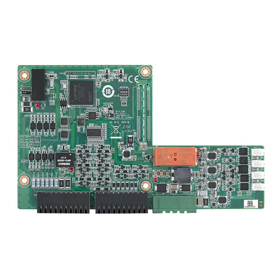
This chapter provides an overview of Advantech AIIS Vision System module AIIS- 1882, ranging the product lineups, features, driver, utility and accessories. The AIIS-1882 is a 4-ch lighting control with 12-ch isolated DI/16-ch isolated DO expansion module. Each lighting control channel contains one trigger input and a PWM output (for lighting). -
Page 13: Software Utility
AIIS-1882. All these software pack- ages are available on the Advantech website: http://www.advantech.com/. The Advantech Navigator is a utility that allows you to set up, configure and test your device, and later stores your settings in a proprietary database. - Page 14 AIIS-1882 User Manual...
-
Page 15: Chapter 2 Installation And Field Application
Chapter Installation and Field Application... -
Page 16: Installation
Remove I/O panel Figure 2.1 Disassembling the enclosure of AIIS-3411 Then, assemble the AIIS-1882 board in the chassis, lighting cables to the front panel, finally the I/O panel back to the front panel: Screw the four screw posts back into the holes that they came from. - Page 17 Plug the other end of the lighting cables into the front panel, CN10 to LT0, CN11 to LT1, CN12 to LT2, CN13 to LT3. (figure 2.3). Screw the I/O panel back onto the front panel. Screw the top enclosure back onto the AIIS-3411 Figure 2.2 Assemble the AIIS-1882 into AIIS-3411 AIIS-1882 User Manual...
- Page 18 Figure 2.3 Lighting cable assembly Figure 2.4 Module support pad sticking AIIS-1882 User Manual...
-
Page 19: Signal Connection And Pin Assignment
Signal Connection and Pin Assignment 2.2.1 Isolated Digital Input and Trigger The AIIS-1882 has 4 trigger inputs and 12 digital inputs. The digital input and trigger accepts only wet contact. Figure 2.5 Isolated digital input and trigger connection 2.2.2 Isolated Digital Output The digital outputs of AIIS-1882 are designed sink type and source type switchable via software. -
Page 20: Lighting Output
2.2.3 Lighting Output The lighting output provides internal 12V at maximum 1A capacity for each channel. Connecting external power could increase the capacity to 2A to each channel, and also 24V option. Figure 2.8 Lighting output connection AIIS-1882 User Manual... -
Page 21: Pin Assignment
2.2.4 Pin Assignment Figure 2.9 Layout view of AIIS-1882 Figure 2.10 Front view of AIIS-1882 Connector Name Description Connector Number on Board DI/TRG Connector for digital input and trigger input Connector for digital output DC IN External power for lighting output 1~4... - Page 22 1, 4 2-pin Lighting Connectors (LT0~LT3) The connector that AIIS-1882 provides by default is a 2-pin connector. If the lighting to be connected with it is 3-pin, then the 3-pin accessories (front panel and cable) need to be purchased separately. The pin definition for a 2-pin connector is shown below: Figure 2.13 Pin assignment of 2-pin lighting connector...
-
Page 23: Chapter 3 Function Details
Chapter Function Details... -
Page 24: Digital Input
Digital Input The AIIS-1882 has digital input function. The following sections describe the digital input acquisition mechanism. For detailed specifications of the functions, refer to Appendix A for details. 3.1.1 Digital Input Functions There are two functions, interrupt and debounce filter other than the input value read- ing function. -
Page 25: Instant Digital Input Acquisition
With instant digital input acquisition, the software controls the sample timing. Each time the software sends a “read instant digital input sample” command, the state of all digital input channels is sampled as shown in Figure 3.8. Figure 3.6 Instant digital input acquisition. AIIS-1882 User Manual... -
Page 26: Digital Output
Digital Output The AIIS-1882 has digital output function. The following sections describe the digital output update/generation mechanism. For detailed specification of the functions. refer to Appendix A. 3.2.1 Static Digital Output Update With static digital output update, the digital output state is updated only when the soft- ware sends a “write static digital output sample”... - Page 27 PWM output respectively. The output count specifies the number of PWM period that the output generates in each output cycle. The configuration interface in Navigator is as shown below: Figure 3.10 PWM properties in Navigator AIIS-1882 User Manual...
-
Page 28: Infinite Lighting Output
In SDK programming reference, the corresponded parameters could also be found. The prototype of PWM high/low argument structure declaration could be found in C:\Advantech\DAQNavi\Inc\bdaqctrl.h. (In this manual, we take C++ as programming example for guidance. Other programming languages follow the same concept and programming style.) -
Page 29: Finite Lighting Output Period
The table below lists some examples for different settings and results. High (ms) Low (ms)* Output Count Strobe Duration (ms) * Low could be set to any figure, as long as it wouldn’t affect the cycle time. AIIS-1882 User Manual... -
Page 30: Trigger Mode Setting For Lighting Output
Trigger Mode Setting for Lighting Output There are two trigger modes in AIIS-1882, which can be configured according to the application scenario: finite pulse generation and gated pulse generation. The modes could be determined in trigger settings. There are four modes to choose from in Trig- ger Edge: Rising edge, Falling edge, High and Low. -
Page 31: Device Description And Configuration
The Device Description is used to differentiate the modules in the system. It's given by combining the model name and boardID (0 for AIIS-1882). You can change the description in Navigator, or just leave it as default. The description is used in your own program in order to get control or device handler from the device. -
Page 32: Device Test In Navigator Utility
Device Test in Navigator Utility To test the functions of AIIS-1882, the Navigator utility should be installed in advance. The AIIS-1882 provides digital input, digital output and PWM lighting output. All of these function tests can be found in Device Test in Navigator. The parameter set in the Profile page will be applied to Device Test, as long as the profile is saved. - Page 33 Figure 3.19 Device Test for digital output PWM Lighting Output Switch the tab to Counter, then connect the lighting directly to LT1~4. Set the PWM high/low period. Check the Start box will start the lighting output. Figure 3.20 Device Test for lighting output AIIS-1882 User Manual...
- Page 34 AIIS-1882 User Manual...
-
Page 35: Chapter A Specifications
Appendix Specifications... -
Page 36: Lighting Output (Pwm)
Edge detection Rising edge, falling edge, or both edges, software configurable per channel Pattern match detection: By port detection, each channel can be Interrupt enabled or disabled by software independently Frequency: 1 kHz max. State latch: Latch port state when interrupt occurs AIIS-1882 User Manual... -
Page 37: Digital Output
1x 4-pin connector for external power input Dimensions (L x W) 175 x 101 mm (6.89" x 3.98") Operating Temperature 0 ~ 60°C (32 ~ 140°F) Storage Temperature -40 ~ 70°C (-40 ~ 158°F) Storage Humidity 5 ~ 95% RH (non-condensing) Function Block AIIS-1882 User Manual... - Page 38 No part of this publication may be reproduced in any form or by any means, such as electronically, by photocopying, recording, or otherwise, without prior written permission from the publisher. All brand and product names are trademarks or registered trademarks of their respective companies. © Advantech Co., Ltd. 2022...
Need help?
Do you have a question about the AIIS-1882 and is the answer not in the manual?
Questions and answers