
Related Manuals for Advantech APAX-5580


Summary of Contents for Advantech APAX-5580
- Page 1 User Manual APAX-5580 High Performance DIN-Rail PC Controller w/ 2xGbE, 2 x mPCIe, 4 x USB, VGA...
- Page 2 No part of this manual may be reproduced, copied, translated or transmitted in any form or by any means without the prior written permission of Advantech Co., Ltd. Information provided in this manual is intended to be accurate and reliable. How- ever, Advantech Co., Ltd.
- Page 3 Because of Advantech’s high quality-control standards and rigorous testing, most of our customers never need to use our repair service. If an Advantech product is defec- tive, it will be repaired or replaced at no charge during the warranty period. For out- of-warranty repairs, you will be billed according to the cost of replacement materials, service time and freight.
- Page 4 Technical Support and Assistance Visit the Advantech web site at www.advantech.com/support where you can find the latest information about the product. Contact your distributor, sales representative, or Advantech's customer service center for technical support if you need additional assistance. Please have the following information ready before you call: –...
- Page 5 The sound pressure level at the operator's position according to IEC 704-1:1982 is no more than 70 dB (A). DISCLAIMER: This set of instructions is given according to IEC 704-1. Advantech disclaims all responsibility for the accuracy of any statements contained herein.
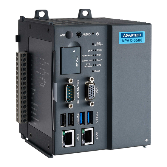
- Page 6 APAX-5580 User Manual...
-
Page 7: Table Of Contents
1.4.2 Hardware Specifications ............... 4 Chapter Hardware Functionality .......5 Introduction ....................6 Figure 2.1 Front Panel of APAX-5580 ......... 6 Figure 2.2 APAX-5580 Dimensions ..........6 APAX-5580 Interface (COM1)..............7 2.2.1 RS-232 Interface (COM 1) ............7 2.2.2 Automatic Data Flow Control Function for RS-485 ....... 7 LAN: Ethernet Connector ................ - Page 8 LED Indicators ..................32 Table A.10:PWR LED ..............32 Table A.11:RUN LED..............32 Table A.12:SATA LED ..............32 Table A.13:ERR LED..............32 Table A.14:Over Temp LED ............32 Table A.15:Abnormal Voltage LED..........32 Table A.16:SYS Recovery LED ..........33 APAX-5580 User Manual viii...
-
Page 9: Chapter 1 Overview
Chapter Overview This chapter provides an overview of APAX-5580 specifications. Sections include: Introduction Hardware specification Safety precautions Chassis dimensions... -
Page 10: Introduction
The APAX-5580 can operate in wide temperature ranges from -20 to 60°C. The APAX-5580 also uses an Intel Core i7/i3/Celeron CPU and up to 8G DDR3 RAM. The APAX-5580 provides great expansion including 2 x Mini-PCIe and SIM card sup- port. -
Page 11: Accessories
Accessories Please refer below for the accessory list: mPCIe screws (Advantech P/N: 1935020300) 2 x PCS jumpers (Advantech P/N: 1653302122) Driver DVD Warranty card If anything is missing or damaged, contact your distributor or sales representative immediately. -
Page 12: Hardware Specifications
Dimensions (W x D x H) 128 x106 x110mm Enclosure Aluminum Housing Mounting DIN-Rail, Wall mount Weight (Net) 1.8kg (4.0lbs) Power Requirement ±20% Power Consumption 28W(Typical), 72W(Max) Operation Temperature -10~60°C Storage Temperature -40~85°C Relative Humidity 10~95%@40°C (non-condensing) APAX-5580 User Manual... -
Page 13: Chapter 2 Hardware Functionality
Chapter Hardware Functionality This chapter shows how to setup the APAX-5580’s hardware func- tions, including connecting peripherals, setting switches and indicators. Sections include: Peripherals RS-232 Interface RS-422/485 Interface LAN / Ethernet Connector Power Connector Audio Connector ... -
Page 14: Introduction
Introduction The following figures show the connectors on APAX-5580. The following sections give you information about each peripheral. Figure 2.1 Front Panel of APAX-5580 Figure 2.2 APAX-5580 Dimensions APAX-5580 User Manual... -
Page 15: Apax-5580 Interface (Com1)
The USB interface supports Plug and Play, which enables you to connect or discon- nect a device whenever you want, without turning off the computer. The APAX-5580 provides four connectors of USB interfaces, which gives complete Plug & Play and hot swapping for up to 127 external devices. -
Page 16: Rtc Battery Specification
RTC Battery Specification The APAX-5580 has an RTC Battery to ensure the setting in bios and system clock can be kept, even with power disconnected for a short time. Type: Panasonic BR-1/2AAC2P (LITH Battery) Output Voltage: 3 V Location: Refer to the figure below ... -
Page 17: Pci Express Mini Card Socket
2.10 PCI Express Mini Card Socket The APAX-5580 supports two sockets for one full size and one half size PCI Express mini cards. The first interface(CN2) is with a SIM card slot. The second interface (CN44) is a half size PCI Express mini card. Users can easily install WLAN, GPRS, 3G, GPS and other communication cards using those interface. -
Page 18: Expansion Module (Apax-5402 Series)
To add the PCI express module or APAX I/O module, you need purchase APAX-5402 series to expand I/O capacity. After hardware installation, download the necessary driver and library: APAX I/O driver and library, from www.advantech.com/support Caution! Make sure the whole system is switched off when you are installing the APAX-5402 series and peripheral I/O Module. - Page 19 Note! APAX-5402L leverages new technology which enables the CPU to han- dle the APAX bus. As a result, a driver is needed to complete the setup of APAX-5402L. Please download driver from our support website. APAX-5580 User Manual...
- Page 20 APAX-5402-E2A1AE and APAX-5402L-E2A2AE is two pieces. If you need to add more than two pieces use an external power. source. First, you need to add a plastic plate on the right hand side of APAX-5580 (PN: 1930002141). Attach with four screws as shown below.
- Page 21 Finally, the system should look like the following configuration: Note! Before installing the APAX-5402 module on APAX-5580, please make sure the power is off for at least 30 seconds to avoid the remaining capacitive effect from damaging the system. APAX-5580 User Manual...
- Page 22 APAX-5580 User Manual...
-
Page 23: Chapter 3 Initial Setup
Chapter Initial Setup This chapter introduces how to initialize the APAX-5580/. Sections include: Inserting an mSATA Card Chassis Grounding Connecting Power BIOS Setup and System Assign- ments... -
Page 24: Inserting A Msata
Screw the two screws on board to fix mSATA. Screw back the bottom cover. Chassis Grounding APAX-5580 provides good EMI protection and a stable grounding base. There is an easy-to-connect chassis grounding point to use. Figure 3.1 Chassis Grounding Connection Please also note that system ground and chassis ground are separated in the APAX-5580. -
Page 25: Installing A Wireless Lan Card And Antenna
Installing a Wireless LAN Card and Antenna Please contact Advantech to prepare the following optional kit: Antenna The internal cable: 1750006043 (15cm) Wireless Module (PCI Express mini card) One of the suggested modules is EWM-W151H01E which is a verified Wireless IEEE 802.11b/g/n module... -
Page 26: Bios Setup
Press “F2” in the boot-up screen to enter the BIOS setup utility. Please follow the instruction on the screen to do the necessary settings. Note! You can try to “Load Optimized Defaults” from the BIOS Setup manual if the APAX-5580 does not work properly. APAX-5580 User Manual... -
Page 27: Amt Configuration
This item allows users to enable or disable ASF Configure Function. Activate Remote Assistance Process This item allows users to enable or disable PET event progress to receive PET events or not. USB Configure This item allows users to enable or disable USB Configure Function. APAX-5580 User Manual... - Page 28 AMT CIRA Timeout OEM defined time out for MPS connection to be established. Watchdog This item allows users to enable or disable WatchDog Timer. OS Timer Sets OS Watchdog Timer. BIOS Timer Sets BIOS Watchdog timer. APAX-5580 User Manual...
-
Page 29: Teaming Configuration
Please install the OS and LAN driver first. After entering the OS, please right click the mouse on Network adaptors to con- figure the Network Connection properties in the device manager. Set Teaming with other adapters in Teaming and then press New Team. APAX-5580 User Manual... - Page 30 Select the adapters to include in this team then press Next. Specify the name for the team then press Next. Select a team mode. Here Adaptive Load Balancing is chosen. APAX-5580 User Manual...
- Page 31 Finally, the wizard has the settings needed to create the team, the Network adapters will show as a TEAM in the device manager. APAX-5580 User Manual...
- Page 32 APAX-5580 User Manual...
-
Page 33: System Settings And Pin Assignments
Appendix System Settings and Pin Assignments... -
Page 34: Board Connectors And Jumpers
Board Connectors and Jumpers There are several connectors and jumpers on the APAX-5580 board. The following sections tell you how to configure the APAX-5580 hardware setting. Figure A.1 shows the locations of the APAX-5580’s connectors and jumpers. Figure A.1 Connector & Jumper Locations (front) Table A.1: Connectors and Jumpers... - Page 35 Termination Resistor Select This switch is used to select Termination Resistor (120 ohm) for long dis- Description tance transmission or device matching. RS422 OFF RS485 OFF RS422 OFF RS485 ON RS422 ON RS485 OFF RS422 ON RS485 ON APAX-5580 User Manual...
-
Page 36: Sw102 Function Switch
A.1.1 SW102 Function Switch The bottom of APAX-5580 provides one PCI express mini card for mSATA HDD. You can install your system disk from this interface. SW102 is the function switch for the following functions; refer to this table for each DIP switch and its function: Table A.4: SW102 Selection... -
Page 37: Rs-232 Standard Serial Port
RS-232 Standard Serial Port Table A.5: RS-232 Serial Port Pin Assignments Pin Name RS-422/485 Serial Port Table A.6: RS-422/485 Serial Port Pin Assignments RS-422 RS-485 Data- Data+ APAX-5580 User Manual... - Page 38 Power Connector (PWR) Table A.7: Power connector pin assignments V1+ (24V +V_CHG BATT +V BATT BATT CHG PRENT# BATT SMB CLK BATT SMB DAT GND (Earth) BATT CHG SMBALERT BATT CHG EN APAX-5580 User Manual...
- Page 39 Black Table A.9: USB 3.0 Connector Pin Assignments Signal Name Description VBUS Power USB2.0 differential pair Ground for power return StdA_SSRX- SuperSpeed receiver differential pair StdA_SSRX+ GND_DRIAN Ground for signal return StdA_SSTX- SuperSpeed transmitter differential pair StdA_SSTX+ APAX-5580 User Manual...
- Page 40 OS Recovery Table A.14: Over Temp LED Description User Defined BIOS Setting Normal LED Status Over temp Green OS Recovery Table A.15: Abnormal Voltage LED Detect AC1 and AC2 power high and low limit voltage Description BIOS Setting Safety LED Status Abnormal* Green OS Recovery *Due to the resolution of the chipset, the real lower limitation will be around 19.3V (2LSB) APAX-5580 User Manual...
- Page 41 When the system starts the OS recovery processes, ERR LED. The Over temp LED, Abnormal voltage LED will flash one-by-one in green and follow this sequence: ERR LED→Over temp LED→Abnml voltage LED→ERR LED→Over temp LED→Abnml voltage LED... APAX-5580 User Manual...
- Page 42 No part of this publication may be reproduced in any form or by any means, electronic, photocopying, recording or otherwise, without prior written permis- sion of the publisher. All brand and product names are trademarks or registered trademarks of their respective companies. © Advantech Co., Ltd. 2014...
Need help?
Do you have a question about the APAX-5580 and is the answer not in the manual?
Questions and answers