Toshiba MMD-AP0724H2UL Service Manual
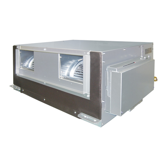
High static ducted type
Hide thumbs
Also See for MMD-AP0724H2UL:
- Engineering data book (213 pages) ,
- Wiring diagram (16 pages)

Related Manuals for Toshiba MMD-AP0724H2UL


Summary of Contents for Toshiba MMD-AP0724H2UL
- Page 1 All manuals and user guides at all-guides.com FILE NO. A10-1506 SERVICE MANUAL AIR-CONDITIONER (MULTI TYPE) <High Static Ducted Type> MMD- AP0724H2UL MMD- AP0964H2UL R410A PRINTED IN JAPAN, Aug., 2015 ToMo – 1 –...
-
Page 2: Table Of Contents
All manuals and user guides at all-guides.com CONTENTS SAFETY CAUTION ................3 1. SPACIFICATIONS ................8 2. CONSTRUCTION VIEWS (EXTERNAL VIEWS) ......9 3. WIRING DIAGRAM ............... 10 4. PARTS RATING ................11 5. FAN CHARACTERISTIC .............. 12 6. REFRIGERATING CYCLE DIAGRAM ......... 15 7. -
Page 3: Safety Caution
All manuals and user guides at all-guides.com SAFETY CAUTION The important contents concerned to the safety are described on the product itself and on this Service Manual. Please read this Service Manual after understanding the described items thoroughly in the following contents (Indications/Illustrated marks), and keep them. - Page 4 All manuals and user guides at all-guides.com WARNING Before troubleshooting or repair work, check the earth wire is connected to the earth terminals of the main unit, otherwise an electric shock is caused when a leak occurs. If the earth wire is not correctly connected, contact an electric engineer for rework. Check earth wires.
- Page 5 All manuals and user guides at all-guides.com WARNING After the work has finished, be sure to use an insulation tester set (500V Megger) to check the resistance is 2MΩ or more between the charge section and the non-charge metal section (Earth position). If the resistance value is low, a disaster such as a leak or electric shock is caused at user’s Insulator check side.
- Page 6 All manuals and user guides at all-guides.com • Refrigerant (R410A) This air conditioner adopts HFC type refrigerant (R410A) which does not deplete the ozone layer. 1. Safety Caution Concerned to Refrigerant (R410A) The pressure of R410A is high 1.6 times of that of the former refrigerant (R22). Accompanied with change of refrigerant, the refrigerating oil has been also changed.
- Page 7 All manuals and user guides at all-guides.com 4. Tools 1. Required Tools for R410A Mixing of different types of oil may cause a trouble such as generation of sludge, clogging of capillary, etc. Accordingly, the tools to be used are classified into the following three types. 1) Tools exclusive for R410A (Those which cannot be used for conventional refrigerant (R22)) 2) Tools exclusive for R410A, but can be also used for conventional refrigerant (R22) 3) Tools commonly used for R410A and for conventional refrigerant (R22)
-
Page 8: Spacifications
All manuals and user guides at all-guides.com 1. SPACIFICATIONS Concealed Duct High Static Pressure Type AP0724H2UL AP0964H2UL Model name MMD- Cooling Capacity kBtu/h Heating Capacity kBtu/h Power supply 230V(208/230V) 1phase 60Hz Electrical charastaristics Power consumption(208V / 230V) 1.37 / 1.44 1.20 / 1.63 Appearance Zinc hot dipping steel plate... -
Page 9: Construction Views (External Views)
All manuals and user guides at all-guides.com 2. CONSTRUCTION VIEWS (EXTERNAL VIEWS) ³ – 9 –... -
Page 10: Wiring Diagram
All manuals and user guides at all-guides.com 3. WIRING DIAGRAM – 10 –... -
Page 11: Parts Rating
All manuals and user guides at all-guides.com 4. PARTS RATING Model MMD- AP0724H2UL AP0964H2UL STF-200-370-4AR Fan motor Running condenser for fan motor AC 450 V, 12 μF Pulse motor EDM-MD12TF-3 Pulse motor valve EDM-BAOYGTF-1 length: 818 mm TA sensor Lead wire Ø4 size lead wire length: 2000 mm Vinyl tube (Blue) TC1 sensor Ø6 size lead wire length: 2000 mm Vinyl tube (Black) -
Page 12: Fan Characteristic
All manuals and user guides at all-guides.com 5. FAN CHARACTERISTIC MMD-AP0724H2UL Power source: 230 V / 60 Hz Power source: 208 V / 60 Hz External static pressure Standard air flow rate External static pressure Standard air flow rate (in.WG) (cfm) (in.WG) - Page 13 All manuals and user guides at all-guides.com MMD-AP0964H2UL Power source: 230 V / 60 Hz Power source: 208 V / 60 Hz External static pressure Standard air flow rate External static pressure Standard air flow rate (cfm) (cfm) (in.WG) (in.WG) High 1.099 High...
- Page 14 All manuals and user guides at all-guides.com Wire connection change of fan motor This duct is composed of 3 fan motors. To change external static pressure by duct resistance, connect the 3 connectors of the orange lead wires that are connected to the underside of the fan tap changing terminal block to the same number (F1, F2 or F3) terminal.
-
Page 15: Refrigerating Cycle Diagram
All manuals and user guides at all-guides.com 6. REFRIGERATING CYCLE DIAGRAM Liquid side Gas side Strainer Capillary tube Air heat exchanger at indoor side Pulse Motor Valve (PMV) Strainer Sensor (TCJ) Sensor (TC2) Sensor (TC1) Sensor Fan motor (TA) Functional part name Functional outline Pulse Motor Valve (Connector CN082 (6P): Blue) -
Page 16: Control Outline
All manuals and user guides at all-guides.com 7. CONTROL OUTLINE Item Outline of specifications Remarks When power 1) Distinction of outdoor unit supply is reset When the power supply is reset, the outdoors are distinguished and the control is selected according to the distinguished result. - Page 17 All manuals and user guides at all-guides.com Item Outline of specifications Remarks Automatic 1) Based on the difference between Ta and Ts, the capacity control operation capacity is determined by the outdoor unit. COOL HEAT ˚F (˚C) ˚F (˚C) +3.6 (+2) +1.8 (+1) +1.8 (+1) Ts: Setup temp.
- Page 18 All manuals and user guides at all-guides.com Item Outline of specifications Remarks Air speed <HEAT> selection (Continued) Ta ˚F (˚C) L <L+> (–0.9) –1.8 [(–0.5) –1.0] L+ <H> (0) Tsh H <H+> (+0.9) +1.8 [(+0.5) +1.0] <HH> (+1.8) +3.6 [(+1.0) +2.0] (+2.7) +5.4 [(+1.5) +3.0] <HH>...
- Page 19 All manuals and user guides at all-guides.com Item Outline of specifications Remarks Freeze prevention 1. In all cooling operation, the air conditioner TC1: Temperature of indoor control operates as de-scribed below based upon temp. heat exchanger sensor (Low temp. release) detected by TC1, TC2 and TCJ sensors.
- Page 20 All manuals and user guides at all-guides.com Item Outline of specifications Remarks Recovery control The indoor unit which is under STOP/Thermo-OFF • The indoor unit which is for heating status or which operates in [FAN] mode performs the under thermo-OFF (COOL) refrigerant (Oil) following controls when it received the heating refriger- status or which operates in...
- Page 21 All manuals and user guides at all-guides.com Item Outline of specifications Remarks Display of < READY> Displayed on the remote controller • <READY > display [READY] 1) When the following check codes are indicated No display for wireless [HEAT READY] type remote controller •...
- Page 22 All manuals and user guides at all-guides.com Item Outline of specifications Remarks Save operation 1) The save operation starts when SAVE button on the remotecontroller is turned on. 2) While the save operation is performed, segment goes on the screen of the wired remote controller. 3) The request capacity ratio is restricted to approx.
-
Page 23: Applied Control And Function
All manuals and user guides at all-guides.com 8. APPLIED CONTROL AND FUNCTION 8-1. Indoor Controller Block Diagram 8-1-1. When Main (Simple) Wired Remote Controller Connected – 23 –... - Page 24 All manuals and user guides at all-guides.com 8-1-2. When Wireless Remote Controller Kit Connected – 24 –...
- Page 25 All manuals and user guides at all-guides.com 8-1-3. When Both Wired (Simple) Remote Controller and Wireless Remote Controller Kit Connected – 25 –...
- Page 26 All manuals and user guides at all-guides.com 8-1-4. Indoor Printed Circuit Board MCC-1403 – 26 –...
- Page 27 All manuals and user guides at all-guides.com 8-1-5. P.C. Board Optional Switch/Connector Specifications Function Connector No. Pin No. Specification Remarks Fan output DC12 V Factory default setting: ON when indoor unit in operation and OFF when indoor unit at rest Output CN32 * Fan can be operated on its own by pressing FAN...
- Page 28 All manuals and user guides at all-guides.com 8-2. Functions at test run Cooling/Heating test run check The test run for cooling/heating can be performed from either indoor remote controller or outdoor interface P.C. board. 1. Start/Finish operation of test run Test run from indoor remote controller Wired remote controller: Refer to the below item of “Test run”...
- Page 29 All manuals and user guides at all-guides.com <In case of wireless remote controller (TCB-AX21UL)> Procedure Description Turn on power of the air conditioner. The operation is not accepted for 5 minutes when power has been turned on at first time after installation, and 1 minute when power has been turned on at the next time and after.
- Page 30 All manuals and user guides at all-guides.com Check function for operation of indoor unit (Functions at indoor unit side) This function is provided to check the operation of the indoor unit singly without communication with the remote controller or the outdoor unit. This function can be used regardless of operation or stop of the system. However, if using this function for a long time, a trouble of the equipment may be caused.
- Page 31 All manuals and user guides at all-guides.com 8-3. Method to Set Indoor Unit Function DN Code (When performing this task, be sure to use a wired remote control- ler.) <Procedure> To be performed only when system at rest CODE No. Push the buttons simultaneously and hold for at SET DATA...
- Page 32 All manuals and user guides at all-guides.com Function CODE No. (DN Code) Table (Includes All Functions Needed to Perform Applied Control on Site) Item Descrip tio n At sh ip men t Filter display delay timer 0000: None 0001: 150H According to type 0002: 2500H 0003: 5000H...
- Page 33 All manuals and user guides at all-guides.com 8-4. Applied Control in Indoor Unit Remote location ON/OFF control box (TCB-IFCB-4UL) [Wiring and setup] • Use the exclusive connector for connection with the indoor control P.C. board. • In a group control, the system can operate when connecting with any indoor unit (Control P.C. board) in the group.
- Page 34 All manuals and user guides at all-guides.com Ventilating fan control from remote controller [Function] • The start/stop operation can be operated from the wired remote controller when air to air heat exchanger or ventilating fan is installed in the system. •...
- Page 35 All manuals and user guides at all-guides.com Leaving-ON prevention control [Function] • This function controls the indoor units individually. It is connected with cable to the control P.C. board of the indoor unit. 2E 2E 2E 2E 2E • In a group control, it is connected with cable to the indoor unit (Control P.C. board), and the CODE No. is set to the connected indoor unit.
- Page 36 All manuals and user guides at all-guides.com Address setup (Manual setting from Wired remote controller) In case that addresses of the indoor units will be determined prior to piping work after wiring work • Set an indoor unit per a remote controller. (Example of 2-lines cabling) (Real line: Wiring, Broken line: Refrigerant pipe) •...
- Page 37 All manuals and user guides at all-guides.com Confirmation of indoor unit No. position 1. To know the indoor unit addresses though position of the indoor unit is recognized • In case of individual operation (Wired remote controller : indoor unit = 1 : 1) (Follow to the procedure during operation) <Procedure>...
- Page 38 All manuals and user guides at all-guides.com How to check all the unit No. from an arbitrary wired remote controller <Procedure> Carry out this procedure during stop of system. The indoor unit No. and the position in the identical refrigerant piping can be checked. An outdoor unit is selected, the identical refrigerant piping and the indoor unit No.
- Page 39 All manuals and user guides at all-guides.com How to change an indoor unit address by using a wired remote control Use this method to change the address of indoor units (one to one or group control) that have had the original address set automatically.
- Page 40 All manuals and user guides at all-guides.com How to change all indoor addresses from an arbitrary wired remote controller (It is possible when setting has finished by automatic addresses.) Contents: The indoor unit addresses in each identical refrigerant piping line can be changed from an arbitrary wired remote controller.
- Page 41 All manuals and user guides at all-guides.com Function to clear error 1. Clearing method from remote controller How to clear error of outdoor unit In the unit of refrigerant line connected by indoor unit of the remote controller to be operated, the error of the outdoor unit currently detected is cleared.
- Page 42 All manuals and user guides at all-guides.com Monitoring function of remote controller switch When using the remote controller (Model Name: RBC-AMT32UL), the following monitoring function can be utilized. Calling of display <Contents> The temperature of each sensor of the remote controller, indoor unit and outdoor unit and the operating status can be checked by calling the service monitor mode from the remote controller.
- Page 43 All manuals and user guides at all-guides.com CODE No. Data name Display format Unit Remote controller display example Room temperature (During control) ×1 ˚F [0081]=71˚F(27˚C) Room temperature (Remote controller) ×1 ˚F Indoor suction temperature (TA) ×1 ˚F Indoor coil temperature (TCJ) ×1 ˚F Indoor coil temperature (TC2)
- Page 44 All manuals and user guides at all-guides.com Changing of settings for Celsius display • Push button if the unit stops. ON / OFF Procedure Push simultaneously buttons for 4 seconds or more. TEST 10 10 10 10 10 After a while, the display part flashes as shown right. Check the displayed CODE No. is [ 1 1 1 1 1 0 0 0 0 0 •...
-
Page 45: Troubleshooting
All manuals and user guides at all-guides.com 9. TROUBLESHOOTING 9-1. Overview (1) Before engaging in troubleshooting (a) Applicable models All Super Module Multi (SMMS-i) models. (Indoor units: MMD-APOOO, Outdoor units: MMY-MAPOOO) (b) Tools and measuring devices required Screwdrivers (Philips, flat head), spanners, long-nose pliers, nipper, pin to push reset switch, etc. Multimeter, thermometer, pressure gauge, etc. - Page 46 All manuals and user guides at all-guides.com 9-2. Troubleshooting Method The remote controllers (main remote controller and central control remote controller) and the interface P.C. board of an outdoor unit are provided with an LCD display (remote controller) or a 7-segment display (outdoor interface P.C.
- Page 47 All manuals and user guides at all-guides.com (Error detected by main remote controller) Check code Display of receiving unit Outdoor 7-segment display Indicator light block Typical fault site Description of error Main remote controller Operation Timer Ready Sub-code Flash No master remote controller, Signals cannot be received from indoor unit;...
- Page 48 All manuals and user guides at all-guides.com List of Check Codes (Outdoor Unit) IPDU: Intelligent Power Drive Unit (Inverter P.C. board) : Lighting, : Flashing, : Goes off (Errors detected by SMMS-i outdoor interface - typical examples) ALT.: Flashing is alternately when there are two flashing LED SIM: Simultaneous flashing when there are two flashing LED Check code Display of receiving unit...
- Page 49 All manuals and user guides at all-guides.com Check code Display of receiving unit Outdoor 7-segment display TCC-LINK Indicator light block Typical fault site Description of error central control or main remote Operation Timer Ready Sub-code controller Flash display Outdoor suction Outdoor suction temperature sensor (TS1) has –...
- Page 50 All manuals and user guides at all-guides.com Check code Display of receiving unit Outdoor 7-segment display TCC-LINK Indicator light block central control Typical fault site Description of error or main remote Operation Timer Ready Sub-code controller Flash display A3-IPDU Fan A3-IPDU IPDU IPDU...
- Page 51 All manuals and user guides at all-guides.com (Errors detected by IPDU featuring in SMMS-i standard outdoor unit - typical examples) Check code Display of receiving unit Outdoor 7-segment display TCC-LINK Indicator light block central control Typical fault site Description of error or main remote Operation Timer Ready Sub-code...
- Page 52 All manuals and user guides at all-guides.com 9-3. Troubleshooting Based on Information Displayed on Remote Controller Using main remote controller (RBC-AMT32UL) (1) Checking and testing When a fault occurs to an air conditioner, a check code and indoor unit No. are displayed on the display window of the remote controller.
- Page 53 All manuals and user guides at all-guides.com Using indoor unit indicators (receiving unit light block) (wireless type) To identify the check code, check the 7-segment display on the header unit. To check for check codes not displayed on the 7-segment display, consult the “List of Check Codes (Indoor Unit)” in “9-2. Troubleshooting Method”.
- Page 54 All manuals and user guides at all-guides.com Light block Check code Cause of fault Heat exchanger temperature sensor (TCJ) error Operation Timer Ready Heat exchanger temperature sensor (TC2) error Indoor unit temperature sensor Heat exchanger temperature sensor (TC1) error errors Ambient temperature sensor (TA) error Alternate blinking Discharge temperature sensor (TF) error...
- Page 55 All manuals and user guides at all-guides.com Light block Check code Cause of fault Operation Timer Ready Outdoor EEPROM error Synchronized blinking Other (indications not involving check code) Light block Check code Cause of fault Operation Timer Ready – Test run in progress Synchronized blinking Operation Timer Ready...
- Page 56 All manuals and user guides at all-guides.com 9-4. Check Codes Displayed on Remote Controller and SMMS-i Outdoor Unit (7-Segment Display on I/F Board) and Locations to Be Checked For other types of outdoor units, refer to their own service manuals. Check code Location Error detection...
- Page 57 All manuals and user guides at all-guides.com Check code Location Outdoor 7-segment display Error detection Description System status Check items (locations) Main condition(s) remote detection Check code Sub-code controller Duplicated Indoor Duplicated All stop More than one indoor unit is •...
- Page 58 All manuals and user guides at all-guides.com Check code Location Outdoor 7-segment display Error detection Description System status Check items (locations) Main condition(s) remote detection Check code controller Sub-code Indoor Error in Stop of Periodic communication • Check remote controller unit communication corresponding...
- Page 59 All manuals and user guides at all-guides.com Check code Location Outdoor 7-segment display Error detection Description System status Check items (locations) Main condition(s) remote detection Check code Sub-code controller IPDU All stop Communication is disrupted • Check wiring and A3-IPDU Fan communication between IPDUs (P.C.
- Page 60 All manuals and user guides at all-guides.com Check code Location Outdoor 7-segment display System Error detection Description Check items (locations) Main status condition(s) remote detection controller Sub-code Check code TO sensor All stop Sensor resistance is infinity • Check connection of TO error or zero (open/short circuit).
- Page 61 All manuals and user guides at all-guides.com Check code Location Outdoor 7-segment display System Error detection Description Check items (locations) Main status condition(s) remote detection controller Sub-code Check code Indoor Other indoor Stop of Indoor P.C. board does not • Check for defect in indoor P.C. –...
- Page 62 All manuals and user guides at all-guides.com Check code Location Outdoor 7-segment display Error detection Description System status Check items (locations) Main condition(s) remote detection controller Check code Sub-code Low oil level All stop Operating compressor <All outdoor units in protection detects continuous state of corresponding line to be...
- Page 63 All manuals and user guides at all-guides.com Check code Location Outdoor 7-segment display System Error detection Description Check items (locations) Main status condition(s) remote detection Check code controller Sub-code 01: TK1 oil Oil level All stop No temperature • Check for disconnection of TK1 sensor. circuit error detection change is detected...
- Page 64 All manuals and user guides at all-guides.com Check code Location Outdoor 7-segment display Error detection Description System status Check items (locations) Main condition(s) remote detection controller Check code Sub-code Indoor Duplicated Stop of There is more than one • Check indoor addresses. unit indoor header corresponding...
- Page 65 All manuals and user guides at all-guides.com Check code Location Outdoor 7-segment display Error detection Description System status Check items (locations) Main condition(s) remote detection Check code Sub-code controller Error in No. of All stop Insufficient number of IPDUs • Check model setting of A3-IPDU Fan IPDUs are detected when power is...
- Page 66 All manuals and user guides at all-guides.com Check code Location Outdoor 7-segment display System Error detection Description Check items (locations) Main status condition(s) remote detection controller Check code Sub-code 01: Compressor IPDU Activation of high- All stop High-pressure SW is •...
- Page 67 All manuals and user guides at all-guides.com Check code Location Outdoor 7-segment display Error detection Description System status Check items (locations) Main condition(s) remote detection controller Check code Sub-code Outdoor liquid All stop <During cooling operation> • Check full-close operation backflow When system is in cooling of outdoor PMV (1, 2, 4).
- Page 68 All manuals and user guides at all-guides.com Check code Location Outdoor 7-segment display Error detection Description System status Check items (locations) Main condition(s) remote detection controller Check code Sub-code Detected 4-way valve All stop Abnormal refrigerating cycle • Check for defect in main outdoor unit reversing error data is collected during...
- Page 69 All manuals and user guides at all-guides.com Check code Location Outdoor 7-segment display Error detection AI-NET central Description System status Check items (locations) Main condition(s) control remote detection Check remote controller Sub-code code controller 0 : IGBT circuit IPDU Outdoor fan All stop (Sub code: 0 ) •...
- Page 70 All manuals and user guides at all-guides.com Errors Detected by TCC-LINK Central Control Device Check code Location Error detection Outdoor 7-segment display Main Description System status Check items (locations) condition(s) remote detection controller Sub-code TCC-LINK TCC-LINK Continued Central control device is •...
- Page 71 All manuals and user guides at all-guides.com Checking procedure Part name Measure the resistance value of each winding by using the tester. Fan motor STF200-370-4AR Position Resistance value 12.1 ± 0.97 Ω Black – Red 12.4 ± 0.99 Ω White – Black 3.94 ±...
- Page 72 All manuals and user guides at all-guides.com 9-5. Sensor Characteristics Indoor Unit Temperature sensor characteristics Temperature Resistance [˚F (˚C)] [kΩ] Resistance 32 (0) 33.9 [kΩ] 41 (5) 26.1 50 (10) 20.3 59 (15) 15.9 68 (20) 12.6 77 (25) 10.0 86 (30) 95 (35) 104 (40)
-
Page 73: Detachments
All manuals and user guides at all-guides.com 10. DETACHMENTS WARNING CAUTION Before replacement of the parts, be sure to stop Be sure to put on the gloves at disassembling work: operation of the air conditioner and turn switch of the otherwise an injuly will be caused by a part. - Page 74 All manuals and user guides at all-guides.com Replacing the fuse Electrical control box cover . When exchanging the fuse loosen the (1)screw, and lift up the (2)fuse cover. (1)Screw (2)Fuse cover . After exchanging the fuse return the (2)fuse cover to the original position,and fix it with (1)screw securely.
-
Page 75: Board Exchange Procedures
All manuals and user guides at all-guides.com 11. P. C. BOARD EXCHANGE PROCEDURES Indoor unit 11-1. Replacement of indoor P.C. board Part code Model type P.C. board type 431-6V-502 MMD-AP∗∗∗H2UL series MCC-1403 Points to note when replacing indoor P.C. board assembly The electrically erasable programmable read-only memory (hereinafter EEPROM, IC10) mounted on an indoor P.C. - Page 76 All manuals and user guides at all-guides.com Procedure 1: reading setting data from EEPROM (Read the setting data from EEPROM, including both the factory settings and any modifications made to them on site.) Push the buttons simultaneously and hold for at least 4 seconds. (This number corre- sponds to the same number shown on the Remote Controller Operation Diagram.) * In the case of group control, the unit No.
- Page 77 All manuals and user guides at all-guides.com Procedure 2: replacing P.C. board Replace the faulty P.C. board with a service P.C. board. Be sure to replicate the old jumper setting (removal), and connector short-circuit setting (e.g. CN34) on the service P.C. board. (See the diagram at below.) CN041 (MCC-1403) CN030...
- Page 78 All manuals and user guides at all-guides.com Procedure 3: writing setting data in EEPROM (The EEPROM of the service P.C. board has been set to the factory default values.) Push the buttons simultaneously and hold <Fig. 1 RBC-AMT32UL> for at least 4 seconds. (This number corresponds to the same number shown on the Remote Controller Operation Diagram.) (Under UNIT No.,...
- Page 79 All manuals and user guides at all-guides.com Table CODE No. table (Please record the objective unit data at field) Item Memo At shipment Filter sign lighting time 0002: 2500 hour Dirty state of filter 0000: Standard Central control address 0099: Unfixed Heating suction temp shift 0002: +3.6˚F (+2˚C) PRE-DEF indication selection...
-
Page 80: Exploded Views And Parts List
All manuals and user guides at all-guides.com 12. EXPLODED VIEWS AND PARTS LIST MMD-AP0724H2UL, AP0964H2UL – 80 –... - Page 81 All manuals and user guides at all-guides.com Location Q’ty/Set MMD- Part No. Description AP0724H2UL AP0964H2UL 4312C023 MOTOR, FAN 43146707 MOTOR, PMV, EDM-MD12TF-3 43146729 BODY, PMV 4314J340 EVAPORATOR ASSY 4314Q091 DISTRIBUTOR ASSY 43122106 CASE, FAN 43120237 43047688 NUT, FLARE, 1/2, IN 43149332 SOCKET 43107215...
- Page 82 All manuals and user guides at all-guides.com E-Parts F1,2,3, 10A, 250V, Inrush-withstand Replace with same type and ratings. Remplacez avec le même type et les mêmes valeurs nominales. EH99569301 Location Q’ty/Set MMD- Part No. Description AP0724H2UL AP0964H2UL 43050425 SENSOR ASSY, TC(F6) 43F50426 SENSOR, TA 43F60859...
- Page 83 All manuals and user guides at all-guides.com WARNINGS ON REFRIGERANT LEAKAGE Important Check of Concentration Limit The room in which the air conditioner is to be installed requires a design that in the event of NOTE 2 : refrigerant gas leaking out, its concentration will The standards for minimum room volume are as follows.
- Page 84 All manuals and user guides at all-guides.com TOSHIBA CARRIER CORPORATION 72-34 Horikawa-cho, Saiwai-ku, Kawasaki-shi, Kanagawa 212-8585, JAPAN Copyright © 2015 TOSHIBA CARRIER CORPORATION, ALL Rights Reserved.
Need help?
Do you have a question about the MMD-AP0724H2UL and is the answer not in the manual?
Questions and answers