
Subscribe to Our Youtube Channel
Related Manuals for Toshiba MMD-AP0726HP-E


Summary of Contents for Toshiba MMD-AP0726HP-E
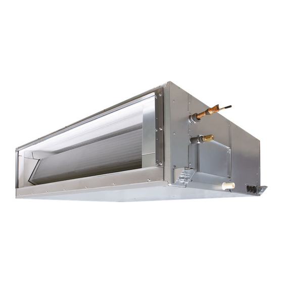
- Page 1 11 1 6 9 50 1 9 5 -1 AIR CONDITIONER (MULTI TYPE) Installation Manual Indoor Unit For commercial use Model name: Concealed Duct High Static Pressure Type MMD-AP0726HP-E MMD-AP0966HP-E English...
-
Page 2: Table Of Contents
Precautions for safety ............3 by Toshiba Carrier Corporation. He or she has been trained to install, maintain, relocate and remove the air... - Page 3 Definition of Protective Gear Warning indications on the air conditioner unit When the air conditioner is to be transported, installed, maintained, repaired or removed, wear protective gloves and ‘safety’ work clothing. In addition to such normal protective gear, wear the protective gear described below when undertaking the special Warning indication Description work detailed in the following table.
-
Page 4: Precautions For Safety
– 3 – • Only a qualified installer(*1) or qualified service person(*1) is Precautions for safety allowed to undertake work at heights using a stand of 50 cm or The manufacturer shall not assume any liability for the damage more or to remove the intake grille of the indoor unit to undertake caused by not observing the description of this manual. - Page 5 • When the air conditioner must be transported by hand, carry it by Installation four or more people. • Suction duct length must be longer than 850 mm. • Do not move or repair any unit by yourself. There is high voltage •...
- Page 6 – 5 – • Tighten the flare nut with a torque wrench in the specified • Do not connect earth wires to gas pipes, water pipes, and manner. Excessive tighten of the flare nut may cause a crack in lightning conductor or telephone earth wires. the flare nut after a long period, which may result in refrigerant •...
- Page 7 • After the work has finished, use an insulation tester set (500 V CAUTION Megger) to check the resistance is 1 MΩ or more between the New refrigerant air conditioner installation charge section and the non-charge metal section (Earth section). •...
-
Page 8: Accessory Parts
– 7 – Accessory parts Selection of installation place Accessory parts Avoid installing in the following places Select a location for the indoor unit where the cool or warm air will circulate evenly. Avoid installation in the following kinds of locations. Part name Q’ty Shape... - Page 9 Installation under high-humidity atmosphere Installation space (Unit: mm) In some cases including the rainy season, especially inside of the ceiling may become high-humidity atmosphere Reserve sufficient space required for installation or service work. (dew-point temperature: 23 °C or higher). Space required for installation and servicing 1.
-
Page 10: Installation
– 9 – Installation of hanging bolt Installation of indoor unit Installation Consider the piping / wiring after the unit is hung to Treatment of ceiling CAUTION determine the location of the indoor unit installation The ceiling differs according to structure of building. and orientation. -
Page 11: Drain Piping
REQUIREMENT Drain piping Removing the cardboard for transportation CAUTION Make sure to remove the protection cardboard for transportation that is inserted in the gap between the top cabinet and the heat exchanger before installing the indoor unit. Following the Installation Manual, perform the drain piping work so that water is properly drained. Apply a heat insulation so as not to cause a dew condensation. - Page 12 – 11 – Connecting drain pipe Heat insulating process Insert flexible drain hose into the drain pipe of main unit as far as it will go. Fix it with hose band. As shown in the figure, cover the flexible hose and hose band with the attached heat insulator up to the bottom of the indoor unit tightly.
- Page 13 Fan characteristics AP072 type AP096 type Standard Air Flow : 3800 (m³/h) Standard Air Flow : 4800 (m³/h) Mid(250Pa) Mid(217Pa) Mid(250Pa) High(250Pa) Mid(183Pa) Mid(217Pa) High(217Pa) Mid(150Pa,117Pa) Mid(183Pa) High(183Pa) Mid(150Pa,117Pa) High(250Pa) High(150Pa) High(217Pa) High(117Pa) High(183Pa) High(83Pa) High(150Pa) High(50Pa) High(117Pa) High(83Pa) High(50Pa) Mid(83Pa) Mid(83Pa) Mid(50Pa)
-
Page 14: Duct Design
– 13 – Duct design Duct design Arrangement (Unit: mm) Referring to the following dimensions, manufacture duct at the local site. In order to prevent short circuits, design (Thickness of plate : 0.8 mm) the duct work so that the intake and discharge openings are not adjacent to <Air outlet>... -
Page 15: Refrigerant Piping
Refrigerant piping Tightening connection CAUTION CAUTION Do not burn the pipe heat insulator. Refrigerant piping Flaring Be careful for the flame, due to the brazing Do not apply excessive torque. Otherwise, the Cut the pipe with a pipe cutter. process on the ceiling. nut may crack depending on the conditions. -
Page 16: Electrical Connection
– 15 – Refrigerant amount to be added Heat insulation process Electrical connection For addition of the refrigerant, add refrigerant “R410A” Apply heat insulation for the pipes separately at liquid referring to the attached Installation Manual of outdoor side and gas side. Power supply wire and unit. - Page 17 Wiring between indoor unit and outdoor unit q Power supply 220 V – 240 V ~, 50 Hz Power supply 208 V – 230 V ~, 60 Hz NOTE Power supply switch/circuit breaker or power supply wiring/fuse rating for indoor units should be selected by the An outdoor unit connected with control wiring between indoor and outdoor units wire becomes automatically accumulated total current values of the indoor units.
- Page 18 – 17 – Wire connection Remote controller wiring Strip off approx. 9 mm the wire to be connected. REQUIREMENT Wiring diagram Connect the wires matching the terminal numbers. Incorrect connection causes a trouble. Pass the wires through the bushing of wire connection holes of the indoor unit. Keep a margin (Approx.
-
Page 19: Applicable Controls
External static pressure Applicable controls Each time button is pushed, indoor settings unit numbers in the control group change cyclically. Select the indoor unit to change Basic procedure for changing REQUIREMENT settings for. <Change on wired remote controller> settings When the air conditioner is used for the first time, it The fan of the selected unit runs and the louvers Set up a tap change based upon the external static will take some moments after the power has been... - Page 20 – 19 – Filter sign setting Remote controller sensor <Setting up on the circuit board of the indoor unit> To set up the external static pressure, use the DIP switch on the circuit board of the wireless reception part. For details, refer to the instruction manual of the wireless remote controller kit. Alternatively, use the switch on the According to the installation condition, the filter sign The temperature sensor of the indoor unit senses indoor micro computer circuit board as shown in the following figure and table.
-
Page 21: Test Run
Test run Maintenance Before test run Wired remote controller CAUTION Before turning on the power supply, carry out the 2, 4 When connecting a return air duct to the unit, the cleaning method of the air filter differs according to the following procedure. -
Page 22: Troubleshooting
– 21 – q Periodic Maintenance Troubleshooting For environmental conservation, it is strongly recommended that the indoor and outdoor units of the air conditioner in use be cleaned and maintained regularly to ensure efficient operation of the air conditioner. Confi rmation and check Confirmation of error log When the air conditioner is operated for a long time, periodic maintenance (once a year) is recommended. - Page 23 Check method (The following check code table explain in SMMS-e.) On the wired remote controller, central control remote controller and the interface P.C. board of the outdoor unit (I/F), a check display LCD (Remote controller) or 7-segment display (on the outdoor interface P.C. board) to display the operation is provided.
- Page 24 – 23 – Check code Wireless remote controller Outdoor unit 7-segment display Sensor block display of receiving unit Check code name Judging device Wired remote controller display Auxiliary code Operation Timer Ready Flash — — Indoor unit TCJ sensor error Indoor unit —...
- Page 25 Check code Wireless remote controller Outdoor unit 7-segment display Sensor block display of receiving unit Check code name Judging device Wired remote controller display Auxiliary code Operation Timer Ready Flash Duplicated indoor units with priority (Displayed in indoor unit with —...
- Page 26 Batch alarm of general-purpose equipment control interface Differs according to error contents of unit with occurrence of alarm Group control follower unit error TCC-LINK Duplication addresses of indoor units in ТСС-LINK central control — — (L20 is displayed.) device ТСС-LINK: TOSHIBA Carrier Communication Link. 49-EN 50-EN...
-
Page 27: Specifications
Declaration of Conformity Specifications Manufacturer: TOSHIBA CARRIER (THAILAND) CO., LTD. Sound pressure level (dBA) 144/9 Moo 5, Bangkadi Industrial Park, Tivanon road, Tambol Bangkadi, Model Weight (kg) Cooling Heating Amphur Muang, Pathumthani 12000, Thailand MMD-AP0726HP-E MMD-AP0966HP-E TCF holder: TOSHIBA CARRIER EUROPE S.A.S... - Page 28 – 27 – Warnings on Refrigerant Leakage Important 2) When there is an effective opening with the adjacent room for ventilation of leaking refrigerant gas Check of concentration limit (opening without a door, or an opening 0.15 % or larger than the respective floor spaces at the top or bottom of the door).
- Page 29 55-EN 56-EN – 28 –...
- Page 30 144 / 9 Moo 5, Bangkadi Industrial Park, Tivanon Road, Tambol Bangkadi, Amphur Muang, Pathumthani 12000, Thailand 1 11695 0195 -1...
Need help?
Do you have a question about the MMD-AP0726HP-E and is the answer not in the manual?
Questions and answers