
Subscribe to Our Youtube Channel
Related Manuals for Caraudio-Systems VL2-MBN2


Summary of Contents for Caraudio-Systems VL2-MBN2
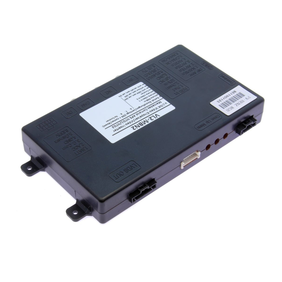
- Page 1 Video-inserter VL2-MBN2 for Mercedes Benz Comand APS NTG1 and NTG2 navigation systems Video-inserter with 2 video- + RGB- + rear-view camera input Version 18.12.2013...
-
Page 2: Table Of Contents
To receive a free update, the interface must be sent in at own cost. Labor cost for and other expenses involved with the software-updates will not be refunded. Version 18.12.2013 VL2-MBN2... -
Page 3: Prior To Installation
Read the manual prior to installation. Technical knowledge is necessary for installation. The place of installation must be free of moisture and away from heat sources. 1.1. Delivery contents Take down the serial number of the interface and store this manual for support purposes: ____________________ Version 18.12.2013 VL2-MBN2... -
Page 4: Checking The Compatibility Of Vehicle And Accessories
5 must use different settings. camera type If set to OFF, the interface switches to factory LVDS picture None when the reverse gear is engaged to display factory rear-view Factory camera or factory PDC picture. After-market Version 18.12.2013 VL2-MBN2... -
Page 5: Installation
The interface is installed on the backside of the monitor panel. Therefore, the head-unit must be removed. Remove head-unit. Remove the upper cover including the DVD/ navigation device. The external daughter PCB is plugged in between the flex cable of the monitor panel and the mainboard of the head-unit. Version 18.12.2013 VL2-MBN2... -
Page 6: Connecting The Flex Cables
Please take note of the contact surfaces of the flex cables during installation. Note: Depending on the navigation the original flex cable possibly needs to be changed into a flex cable in delivery. Version 18.12.2013 VL2-MBN2... -
Page 7: Connections
No liability for vehicle wire colors and pin definition! Quadlock-connector of the vehicle Possible changes by the vehicle manufacturer. The ●● Red/Blue +12Volt Permanent Pin 15 given information must be verified by the installer ● Brown Ground Pin 12 Version 18.12.2013 VL2-MBN2... -
Page 8: Installation Procedure - Function Check
If 2 audio sources shall be used, connect the audio wires and check the audio function ONLY after positive function check proceed with final installation of the video sources! After installation and connection of the real video source(s), adjust picture settings (see chapter 2.5.) Version 18.12.2013 VL2-MBN2... -
Page 9: Picture Settings
Audio pins Definition Audio input signal R/L of source IN2 Audio input signal R/L of source IN1 Audio output signal L/R of factory audio AUX or FM-modulator Ground No function Audio-switch- port Audio-cable Video-interface Version 18.12.2013 VL2-MBN2... -
Page 10: Interface Operation
IN1 to video IN2, also the sound will be switched. 4. Specifications BATT/ACC range 7V ~ 25V Power 0.3A @12V Video input 0.7V~1V Video input formats PAL/NTSC Weight 195g Dimensions (box only) B x H x T 182 x 24 x 100 mm Version 18.12.2013 VL2-MBN2...
Need help?
Do you have a question about the VL2-MBN2 and is the answer not in the manual?
Questions and answers