
Related Manuals for Caraudio-Systems V5-CIC-F


Summary of Contents for Caraudio-Systems V5-CIC-F
- Page 1 Intelligent Solution Interface V5-CIC-F compatible with the F-series BMW with navigation system or radio and 7” or 10.2” monitor with 4pin HSD LVDS connector Version 01.12.2015 V5-CIC-F...
- Page 2 Picture-in-picture mode combining after-market rear-view and front camera picture(s) with factory parking sensor graphics Compatible with all factory video accessories (e.g. rear-view camera, Top-View, nightvison, DVD-changer, TV-tuner) USB update-port for software-updates by consumer Version 01.12.2015 V5-CIC-F...
-
Page 3: Table Of Contents
4.1.1. OSD – Operation 4.1.1.1. 8-button iDrive 4.1.1.2. 2-button iDrive in Mini 4.1.2. OSD – Additional setting options 4.2. Video-in-motion function 4.3. Selecting the interface as current video source 5. Specifications 6. Connections (interface-box) 7. Technical support Version 01.12.2015 V5-CIC-F... - Page 4 To receive a free update, the interface must be sent in at own cost. Labor cost for and other expenses involved with the software-updates will not be refunded. Version 01.12.2015 V5-CIC-F...
-
Page 5: Prior To Installation
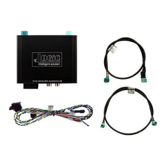
V5C-M636 LVDS cable HW_____ SW_____ CAB-HSD-MR-060-OZ LVDS cable CAB-HSD-DD075-O V5C-UNI02 harness 1.1. Check compatibility of vehicle and accessories Requirements Navigation F-series with navigation system or radio with 7“ or 10“ monitor (F-series) with 4pin HSD LVDS connector Version 01.12.2015 V5-CIC-F... -
Page 6: Setting The Dip Switches Of The Interface-Box V5C-M636
No function CIC-F (F-series), 10“ monitor No function After each change of the dip switch settings you have to execute a power reset of the interface-box! 1.3. LED‘s of the interface-box V5C-M636 Valid input source CAN ok Power Version 01.12.2015 V5-CIC-F... -
Page 7: Connection Schema
CAB-HSD-MR-060-OZ head unit 4-Pin HSD LVDS female vehicle harness Interface-box V5C-M636 FRONT +12V Quadlock female vehicle harness Masse Rear-view camera V5C-UNI02 harness CAN (1) Front camera CAN (2) Rear gear signal iDrive input (+12V) +12V switching outputs Version 01.12.2015 V5-CIC-F... -
Page 8: Installation
Connecting interface-box and harnesses Quadlock male on rear side of the Head Unit Interface-box V5C-M636 FRONT Quadlock female +12V vehicle harness Ground V5C-UNI02 harness Cut off the 8 pin Molex connector from V5C-UNI02 harness (is not needed). Version 01.12.2015 V5-CIC-F... - Page 9 Pin assignment: Cable colour Assignment ● +12V permanent input - Pin15 ● Black Ground - Pin 12 ● Green +12V power output ● Pink +12V power output ● White Rear gear signal input (+12V) Quadlock Version 01.12.2015 V5-CIC-F...
-
Page 10: Lvds Connection
4pin HSD LVDS connector (LVDS-OUT) on the rear of the interface-box V5C-M636. Connect the female 4pin HSD LVDS connector of the LVDS cable CAB-HSD-DD075-O to the pink male 4pin HSD LVDS connector on the rear of the head unit. Version 01.12.2015 V5-CIC-F... -
Page 11: Connection To The Idrive
Pin the green/orange cable CAN-high (green cable CAN-low) of the vehicle harness into pin 1 of the included female 2pin AMP connector. Connect female 2pin AMP connector to 2pin AMP connector (yellow/black and blue/black cable) of harness V5C-UNI02. Version 01.12.2015 V5-CIC-F... -
Page 12: After-Market Front Camera
The pink wire of harness V5C-UNI02 can be used for +12V electric power supply (max. 1A) of the after-market front camera. Configure in the OSD- menu “MISC”, menu item “POWER OUT 2” the designated electric power supply (see chapter “Configurable switching outputs”). Version 01.12.2015 V5-CIC-F... -
Page 13: Settings For Connecting An After-Market Front Camera
(e.g. radio). After deactivation you can’t enable the parking process again until the vehicle is diving faster than 20km/h, the ignition is switched off and on or the PDC will be disabled and enabled again, if existing. Version 01.12.2015 V5-CIC-F... -
Page 14: After-Market Rear-View Camera
On some vehicles the reverse light signal doesn’t exist on the CAN-bus. Connect the white wire of harness V5C-UNI02 to reverse light signal (+12V of reverse light) if the system doesn’t switch to the rear-view camera automatically after the described OSD-setup (see next chapter). Version 01.12.2015 V5-CIC-F... -
Page 15: Settings For Connecting An After-Market Rear-View Camera
(e.g. radio). After deactivation you can’t enable the parking process again until the vehicle is diving faster than 20km/h, the ignition is switched off and on or the PDC will be disabled and enabled again, if existing. Version 01.12.2015 V5-CIC-F... -
Page 16: Configurable Trigger Outputs
+12V when the interface is on (red LED on) Ignition +12V when ignition is on +12V when the rear-view camera input is POWER OUT1 RearCam activated (pink) MISC POWER OUT2 (green) Reverse Gear +12V when reverse gear is engaged Trigger putput deactivated Version 01.12.2015 V5-CIC-F... -
Page 17: Picture Settings
You can change the picture settings in the OSD-menu IMAGE (Operation of the OSD: see chapter “OSD-Operation”). ◦ Brightness ◦ Contrast ◦ Saturation ◦ Hue ◦ Sharpness Note: The picture settings will be retained for each AV-source separately. Version 01.12.2015 V5-CIC-F... -
Page 18: Operation
4. Operation 4.1. OSD – On-screen display You can change the basic configurations of the interface in the OSD (on screen display). 4.1.1. OSD – Operation You can control the OSD by iDrive. 4.1.1.1. 8-button iDrive Version 01.12.2015 V5-CIC-F... -
Page 19: 2-Button Idrive In Mini
(Operation of the OSD: see chapter “OSD-Operation”): OSD-menu Menu item Setting Explication H POSITION 0-xxx Horizontal position of the OSD V POSITION 0-xxx Vertical position of the OSD VERSION X.XX.XX Displays the current SW-version MISC FACTORY RESET Resetting to factory settings Version 01.12.2015 V5-CIC-F... -
Page 20: Video-In-Motion Function
Short press CD button respectively MENU button to switch the video sources (cameras). Each short press will switch to the next enabled input. If all inputs are enabled the order is: FRONT CAM REAR CAM … Inputs which are not enabled are skipped. Version 01.12.2015 V5-CIC-F... -
Page 21: Specifications
Front camera Female input update-connector Mini USB 7. Technical Support Caraudio-Systems Vertriebs GmbH manufacturer/distribution In den Fuchslöchern 3 D-67240 Bobenheim-Roxheim email support@caraudio-systems.de Legal disclaimer: Mentioned company and trademarks, as well as product names/codes are registered trademarks ® of their corresponding legal owners.
Need help?
Do you have a question about the V5-CIC-F and is the answer not in the manual?
Questions and answers