Table of Contents
Advertisement
Advertisement
Table of Contents

Related Manuals for LAUNCH TECH CRT511


Summary of Contents for LAUNCH TECH CRT511
- Page 1 V1.00.002 08-12-2020...
- Page 2 LAUNCH Copyright Information Copyright © 2020 by LAUNCH TECH CO., LTD. All rights reserved. No part of this publication may be reproduced, stored in a retrieval system, or transmitted in any form or by any means, electronic, mechanical, photocopying and recording or otherwise, without the prior written permission of LAUNCH.
- Page 3 LAUNCH LAUNCH the warranty right. nearby. • CAUTION: This tool contains an internal Lithium Polymer battery. The • Don’t connect or disconnect any test equipment while the ignition is on or battery can burst or explode, releasing hazardous chemicals. To reduce the engine is running.
-
Page 4: Table Of Contents
LAUNCH LAUNCH Table of Contents 5.2.3 Copy ID by activation...............36 5.2.4 Program multi-sensor ..............38 1. Introduction ....................1 5.3 TPMS Service ...................39 2. general Information-about oBdII/eoBd ..........3 5.3.1 Relearn procedure ................39 2.1 On-Board Diagnostics (OBD) I ..............3 5.3.2 Part number lookup .................40 2.2 On-Board Diagnostics (OBD) II ..............3 6. -
Page 5: Introduction
LAUNCH 1. Introduction This TPMS activation & diagnostic tool is specially developed by LAUNCH, which enables users to trigger TPMS sensor, program TPMS sensor, perform the relearning procedure and check sensor part number. Additionally, it also supports all 10 modes of OBD II test for a complete diagnosis. With built-in help menus and code definitions, diagnosing and repairing that dreaded Check Engine Light is now easier than ever! This tool provides the following functions:... -
Page 6: General Information-About Obdii/Eobd
LAUNCH LAUNCH 1. Vehicle emissions Control Information (VeCI) Label. It is located 2. general Information-about oBdII/eoBd under the hood or by the radiator of most vehicles. If the vehicle is OBD II compliant, the label will designate “OBD II Certified”. 2.1 on-Board diagnostics (oBd) I Note: With the exception of some 1994 and 1995 vehicles, most vehicles from 1982 to 1995 are equipped with some type of first generation On-Board... -
Page 7: Diagnostic Trouble Codes (Dtcs)
LAUNCH LAUNCH • To standardize communication procedures and protocols between the showed the following: diagnostic equipment (Diagnostic Tools, Code Readers, etc.) and the • A large number of vehicles had deteriorating or degraded emissions-related vehicle’s on-board computer. components. These components were causing an increase in emissions. •... -
Page 8: Location Of The Data Link Connector (Dlc)
LAUNCH LAUNCH most vehicles. If Data Link Connector is not located under dashboard, a label should be there telling location. For some Asian and European vehicles, the DLC is located behind the ashtray and the ashtray must be removed to access the connector. -
Page 9: Obd Ii Monitors
LAUNCH LAUNCH fuel trim refers to dynamic or instantaneous adjustments. Long-term fuel trim enabling Criteria -- Also termed Enabling Conditions. They are the vehicle- refers to much more gradual adjustments to the fuel calibration schedule than specific events or conditions that must occur within the engine before the short-term trim adjustments. -
Page 10: Non-Continuous Monitors
LAUNCH LAUNCH severe, and may cause catalytic converter damage, it commands the MIL 2.6.2 non-Continuous Monitors to “flash” once per second as soon as the misfire is sensed. When the “Non-continuous” Monitors perform and complete their testing once per trip. misfire is no longer present, the MIL reverts to steady “On”... - Page 11 LAUNCH LAUNCH vehicle operation. When the vehicle is operating in closed-loop, the computer converter. The main difference is that a heater is added to bring the catalytic uses the oxygen sensor signal for air/fuel mixture corrections. converter to its operating temperature more quickly. This helps reduce emissions by reducing the converter’s down time when the engine is cold.
-
Page 12: Obd Ii Reference Table
LAUNCH LAUNCH B. Number of trips needed, with a fault present, to set a pending DTC. engine vacuum to draw the fuel vapors from the canister into the engine where the vapors are burned. The EVAP Monitor checks for proper fuel vapor flow to C. -
Page 13: Dtcs And Mil Status
LAUNCH LAUNCH 2.7 dTCs and MIL Status • If the failure is not found on the second Trip, the Pending DTC is erased from the computer’s memory. When the vehicle’s on-board computer detects a failure in an emissions- The MIL will stay lit for both Type “A” and Type “B” codes until one of the related component or system, the computer’s internal diagnostic program following conditions occurs: assigns a diagnostic trouble code (DTC) that points to the system (and... -
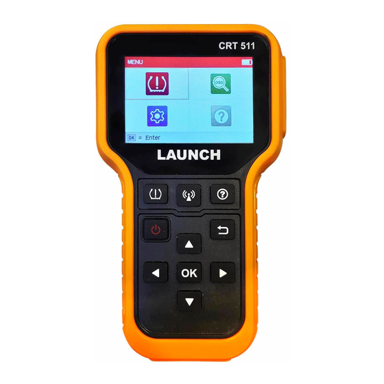
Page 14: Product Descriptions
LAUNCH LAUNCH Insert the memory card into it to read or 3. Product descriptions MeMory Card write the data/file stored in the memory SLoT card. 3.1 general Controls BuTTon Press it to trigger the vehicle sensor. BuTTon Quick access to Help function. BuTTon Returns to previous menu. -
Page 15: Specifications
LAUNCH LAUNCH 6) User Manual Press it for about 3 seconds to turn it on. 7) Sensors (Optional) • Screen On: Press it once to enter hibernate mode. • If the tool is not charged and there is no operation made for the preset auto power-off interval, it will automatically power off. -
Page 16: Initial Use
LAUNCH LAUNCH 4.2 Main Menu 4. Initial use 4.2.1 function modules 4.1 Charging & Turning On/Off The main menu screen includes the following function modules: 4.1.1 Charging There are three methods available for charging the tool. 1. Via aC outlet Connect one end of the charging cable to the charging port of the tool, and other end to the power adaptor. -
Page 17: Settings
LAUNCH LAUNCH 4) datastream units Icon descriptions Set the measurement units of the datastream items (Metric or Imperial). The memory card is ejected or removed from the memory 5) Auto Power Off card slot. This option enables you to set the time to turn off the tool automatically after It appears when the tool is connected to the vehicle’s not being operated. -
Page 18: Tpms Operations
LAUNCH LAUNCH 5. TPMS operations For initial use, please follow the flow chart below to start using it. Enter TPMS Select vehicle manufacturer Figure 5-1 (Select MerCedeS) Select vehicle model 2. Select B Class and press the oK button to enter the vehicle year selection screen. -
Page 19: Check Sensor
LAUNCH LAUNCH 1. Select CHeCK SenSor and press the oK button to enter the following screen. Figure 5-3 (Select 2014~2018) 4. Select 2014~2018 and press the oK button to enter the TPMS function selection screen. Figure 5-5 2. For universal sensors, place the tool alongside the valve stem, point toward the sensor location, and press the button. -
Page 20: Program Sensor
LAUNCH LAUNCH *Id: indicates the sensor ID. Once the sensor is successfully activated and decoded, the tool will sound a beep and the screen will display the sensor data with a tick *P: indicates the tire pressure. *T: indicates the tire temperature. Vol: indicates the battery power level. -
Page 21: Manual Input
LAUNCH LAUNCH Figure 5-12 Once the sensor is successfully programmed, the following screen will appear. Figure 5-10 Press the oK button to start detecting the sensor and writing the new created sensor ID to the LAUNCH-sensor. Figure 5-13 Press the button to return to the previous screen. - Page 22 LAUNCH LAUNCH Use the on-screen virtual keypad to input a random or original (if available) sensor ID and press oK. Figure 5-17 After the sensor is successfully programmed, the following screen will appear. Figure 5-15 Note: Do not enter the same ID for each sensor. Select the wheel which needs to be programmed on the tool, place a LAUNCH-sensor close to the TPMS antenna of the tool.
-
Page 23: Copy Id By Activation
LAUNCH LAUNCH 5.2.3 Copy Id by activation This function allows users to write in the retrieved original sensor data to the LAUNCH-sensor. It is used after the original sensor is triggered. Select CoPy Id By aCTIVaTe and press the oK button to enter. Figure 5-22 Select the specific wheel position and press the oK button to create a sensor Figure 5-20... -
Page 24: Program Multi-Sensor
LAUNCH LAUNCH Figure 5-24 After the sensor is successfully programmed, the following screen will appear. Figure 5-27 Press the button to return to the previous screen. Press the oK button to continue programming other sensors. Figure 5-25 button to return to the previous screen. Press the oK button to Press the 5.3 TPMS Service continue programming other sensors. -
Page 25: Part Number Lookup
LAUNCH LAUNCH used to write the newly programmed sensor IDs into the vehicle’s ECU for 6. oBd diagnosing sensor recognition. This option presents a quick way to check for DTCs, isolate the cause of the illuminated Malfunction Indicator Lamp (MIL), check monitor status prior to emissions certification testing, verify repairs, and perform a number of other services that are emission-related. -
Page 26: Start Obd Diagnostics
LAUNCH LAUNCH Notes: • A plastic DLC cover may be found for some vehicles and you need to remove it before plugging the diagnostic cable. • The cable connector is keyed and will only fit one way. If you have problems connecting the cable connector to the DLC, rotate the connector 180 and try again. - Page 27 LAUNCH LAUNCH automatically read the SAE-standard DTCs and a screen similar to Figure 6-5 Note: In case the diagnostic codes are manufacturer-specific, users need to will appear. select the manufacturer manually and the following prompt message will appear on the screen. Figure 6-5 In Figure 6-3, Figure 6-6...
- Page 28 LAUNCH LAUNCH Figure 6-9 Press oK to erase DTCs, and the following screen will appear: Figure 6-8 Figure 6-10 2. erase Codes Follow the on-screen prompts to turn the ignition on with engine off, press oK Note: When this function is used to erase DTCs from the vehicle’s on-board to clear the DTCs.
- Page 29 LAUNCH LAUNCH • Select View all Items and press oK, the screen will display the dynamic a fault has been performed) to confirm that the repair has been performed data of all data stream items: correctly, and/or to check for Monitor Run Status. Select I/M readiness from the Diagnostic Menu and press oK, the screen will display the I/M readiness result.
- Page 30 LAUNCH LAUNCH retrieve a list of information (provided by the vehicle manufacturer) from the • If View graphic Items is selected in Data stream menu and press oK to vehicle’s on-board computer. This information may include: enter the graphic items selection screen. •...
-
Page 31: Help
LAUNCH LAUNCH 7. Help Note: You are strongly recommended to note down the Serial Number and Register Code in Figure 7-2 since these 2 pieces of information are required while This menu enables you to view device information and OBD introduction. registering your tool. -
Page 32: Register & Update
4). Write down the Serial Number and Register code for later use. Prerequisite conditions: 2. register the scanner on the update tool . 1. Go to http://www.x431.com/CRT511 to download the update tool and install it on the computer. For better experience, it is recommended to register and upgrade the tool 2. -
Page 33: Faq
LAUNCH LAUNCH 9. faQ Note: For initial update, user needs to go through a registration process. Once you finished it, the registration screen will not appear again each time Here we list some frequently asked questions and answers relating to this tool. you click the Device Upgrade button in the future. -
Page 34: Www.x431.Com +86 755 8455 7891
1. Quantity 2. Part number 3. Item description Customer Service If you have any questions on the operation of the unit, please contact local dealer, or contact LAUNCH TECH. CO., LTD: Tel: +86-755-84527891 E-mail: overseas.service@cnlaunch.com www.x431.com +86 755 8455 7891...
Need help?
Do you have a question about the CRT511 and is the answer not in the manual?
Questions and answers