
Related Manuals for LAUNCH TECH X-631


Summary of Contents for LAUNCH TECH X-631
- Page 1 LAUNCH X-631 Wheel Aligner Product Service Manual X-631 Wheel Aligner Product Service Manual No.: 11 LSDC 3111 0003 A Translated by Checked by Approved by Name Alex. Mr. Li Frank Date 20120620 20120628 20120631...
- Page 2 LAUNCH X-631 Wheel Aligner Product Service Manual LAUNCH TECH CO., LTD. ADD: Launch Industrial Park, North of Wuhe Rd, Banxuegang, Longgang, Shenzhen, P. R. China TEL: 400 830 5166 Internet: http://www. cnlaunch.com...
-
Page 3: Table Of Contents
LAUNCH X-631 Wheel Aligner Product Service Manual Table of contents Table of Contents Preface......................................1 Target Reader...................................1 Purpose ....................................1 Required Knowledge ................................1 Summary.......................................1 Function....................................1 Specifications ...................................1 Hardware ......................................1 Computer ......................................1 Hardware Configuration................................1 Operating System..................................1 Computer (HP) Backboard Diagram............................1 Wireless Emitter/Receiver Box ..............................2 Function Explanation Diagram ..............................5... - Page 4 LAUNCH X-631 Wheel Aligner Product Service Manual Table of contents Main chip (ATMEGA128L) Address Code ..........................14 Testing for Main-board Circuit..............................14 CCD Camera Box...................................16 Function Explanation ................................17 Function Description................................17 Specification ...................................17 Camera Assembly ..................................18 Electrical Connection................................19 LCD Display Screen ................................19 Main-board Charging Cable ..............................20 Filter......................................20...
- Page 5 LAUNCH X-631 Wheel Aligner Product Service Manual Table of contents Measurement..................................13 Function Description................................13 Fast Test ....................................13 Function Description................................14 Print Report ....................................14 Help ......................................14 Exit......................................14 Maintenance Guide..................................1 Summary ....................................1 Hardware....................................1 Probe rod cannot be switched on .............................1 Related Factors ..................................1 Checking Sequence .................................1 Incorrect Display after Switching On ............................1...
- Page 6 Check Sequence ..................................4 Computer runs slowly ................................4 Related Factors ..................................4 Check Sequence ..................................4 Appendix 1....................................1 Instructions for waveform testing software of X-631 wheel aligner...................1 Appendix 2....................................1 Circuit Board Elements................................1 Appendix 3....................................1 The Instructions for the Frequency Jumping of RF Modules ....................1 Appendix 4....................................1...
-
Page 7: Preface
The main content of this manual is to introduce the wheel aligner of model X-631. In this manual, author describes the wheel aligner by using a lot of practical pictures and explication to avoid unnecessary misunderstanding caused by over-many special items. -
Page 8: Summary
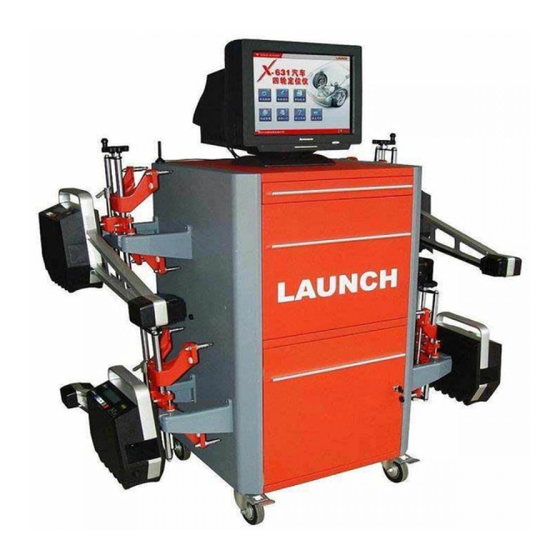
Summary Function X-631 wheel aligner is the product newly developed by Launch Tech Co., Ltd., which adopts lots of new technology and many advanced elements and devices, and has many new functions and higher measurement precision. The X-631 Wheel Aligner can be used to measure the most wheel alignment parameters, such as front wheel toe-in, front wheel camber, caster, Kingpin inclination, maximal steering angle (if equipped with electronic turntable), toe-out on turns, rear wheel toe-in, rear wheel camber, thrust angle, wheelbase difference, tread difference, etc. -
Page 9: Hardware
LAUNCH X-631 Wheel Aligner Product Service Manual Hardware Hardware Computer Hardware Configuration Computer host LENOVO Main-board 946GZ 3.0GHz 256M Hard disc CD-ROM Video display card Integrated Sound card Integrated Network interface card Integrated Operating System Operating system Windows XP Computer (HP) Backboard Diagram... -
Page 10: Wireless Emitter/Receiver Box
Hardware Wireless Emitter/Receiver Box X-631 wheel aligner is equipped with two types of Wireless Emitter/Receiver Modules, 433M and 2.4G. For the Wireless Emitter/Receiver boxes inside the cabinet, their antennas are different. There is a Wireless Emitter/Receiver Module in each probe rod, 433M module is equipped with the antenna of spring shape, and 2.4G module’s antenna is a wire only. - Page 11 LAUNCH X-631 Wheel Aligner Product Service Manual Hardware ANTENNA ON THE LEFT IS FOR 433M MODULE, AND THE RIGHT ONE FOR 2.4G MODULE The following accounts will take 433MHz Module as an example.
- Page 12 LAUNCH X-631 Wheel Aligner Product Service Manual Hardware Voltage between 2 and 3 pin is +3.3V Voltage between 1 and 2 pin is +5V RF PCA Board Back side Front side Voltage Voltage between between and 3 pin is and 2 pin is...
-
Page 13: Function Explanation Diagram
LAUNCH X-631 Wheel Aligner Product Service Manual Hardware After equipped with plastic casing (front and back side pictures) RF Box Function Explanation Diagram Normal/ Frequency setting RF module Socket for antenna Receiver indicator Socket for connecting cable Emitter indicator Power supply indicator... -
Page 14: Working Frequency
LAUNCH X-631 Wheel Aligner Product Service Manual Hardware Plastic box base RF PCA board RF connecting cable XH socket Working Frequency Normal working frequency: 433MHz, and 429~438MHz under the special conditions. Switch Power Supply Function Explanation Live AC220V Null Positive... -
Page 15: Function Description
LAUNCH X-631 Wheel Aligner Product Service Manual Hardware Function Description Switch power supply: input voltage AC220V±10%, output voltage DC9.3±0.1V. When output voltage is incorrect, adjust the potentiometer with a small cross screwdriver to keep the output voltage within the specified range. -
Page 16: Charging Connector
Charging Connector Function Explanation To switch power supply V+ To charging power supply cable To switch power supply V- X-631 cabinet charging power supply converter cable 6PIN flange socket 6PIN flange male socket male X-631cabinet charging power supply cable Function Description Used as the connector between the switch power supply and the charging socket of probe rod, providing the charging voltage of 9.1~9.3V. -
Page 17: Function Explanation
LAUNCH X-631 Wheel Aligner Product Service Manual Hardware Function Explanation Assembly Description LCD screen Level bubble End CCD camera Middle CCD Silica gel key-press camera Aluminum bracket... -
Page 18: Main-Board Of Probe Rod
LAUNCH X-631 Wheel Aligner Product Service Manual Hardware Middle CCD camera Battery Clinometer Probe rod LCD screen main-board Silica gel key-press board Middle explosion diagram End CCD camera End CCD connecting cable End explosion diagram Main-board of probe rod 2-10... -
Page 19: Function Explanation
LAUNCH X-631 Wheel Aligner Product Service Manual Hardware Element side Function Explanation Main processor and interface circuit Power supply and charging circuit 2-11... -
Page 20: Function Description
LAUNCH X-631 Wheel Aligner Product Service Manual Hardware End CCD signal processing circuit Middle CCD signal processing circuit Wireless module related circuit Clinometer related circuit Function Description Accomplish the drive and signal processing for CCD, clinometer and infrared emitter diode. -
Page 21: Connecting Sockets
LAUNCH X-631 Wheel Aligner Product Service Manual Hardware Connecting Sockets 8 9 7 6 3 1 2 5 Charging power supply socket Middle CCD socket Lithium battery socket LCD socket End infrared emitter diode socket Key-press film socket Middle infrared emitter diode socket... -
Page 22: Communication Module
LAUNCH X-631 Wheel Aligner Product Service Manual Hardware Communication Module Emitter indicator Receiver indicator Spring antenna Working voltage 5V Note: Working frequency 433MHz; transmission rate 9600bps,8 data digits, 1 stop digit; When the probe rod receives the signal from the other working with the same frequency, the green indicator will flash, and the red indicator starts flashing when pressing the key-press, and the probe rod will transmit the data;... - Page 23 LAUNCH X-631 Wheel Aligner Product Service Manual Hardware Battery Connect to 9V socket power supply Connect 9V power supply to J10, check with multi-meter if the voltage between J11-1 and J11-2 is 8.3V (normal output). If it is normal, please connect the battery to J11, and check with multi-meter if the voltage difference on R47 is about 100mV.
-
Page 24: Ccd Camera Box
LAUNCH X-631 Wheel Aligner Product Service Manual Hardware After connecting battery to main-board, D15-2 should have the voltage of 12.0V to drive CCD sensor. If there is no the voltage, CCD circuit cannot work. U28_3 After connecting battery to main-board, U28_3 should have the voltage of 5V to supply the peripheric circuits on CCD sensor main-board. -
Page 25: Function Explanation
LAUNCH X-631 Wheel Aligner Product Service Manual Hardware Function Explanation Infrared beam (out) CCD board PCA CCD plastic casing Socket Infrared beam (in) CCD module Raster Filter Silica gel hold-down board Cylinder lens Function Description Adopts linear array CCD module, 2048 pixels, single color;... -
Page 26: Camera Assembly
LAUNCH X-631 Wheel Aligner Product Service Manual Hardware Camera Assembly Front cover of CCD plastic box CCD plastic box Infrared emitter board Cylinder lens Filter CCD drive board(front) CCD drive board(rear) Silica gel hold-down board 2-18... -
Page 27: Electrical Connection
LAUNCH X-631 Wheel Aligner Product Service Manual Hardware Electrical Connection End CCD camera Middle CCD camera LCD Display Screen Backlight cable Front view Data cable strip sockets 2-19... -
Page 28: Main-Board Charging Cable
LAUNCH X-631 Wheel Aligner Product Service Manual Hardware Backlight voltage Rear view Note: 1. Model LMB162GBY, character 2X16; 2. Working voltage 5V, data interface 16PIN. Main-board Charging Cable Charging socket is a 6PIN flange socket, the middle pole is positive, which connects to Red cable, and side pole is negative, to Black cable. -
Page 29: Power Supply Battery
LAUNCH X-631 Wheel Aligner Product Service Manual Hardware Power Supply Battery Specification Lithium battery, 7.4V 4400mAh. 2-21... -
Page 30: Electrical Connection
LAUNCH X-631 Wheel Aligner Product Service Manual Hardware Electrical Connection Connection Explanation 2 Note: There are print marks of J6 and J7 respectively on the connecting cable of the middle CCD and the connecting cable of the end CCD, please do not confuse them when plugging them. - Page 31 LAUNCH X-631 Wheel Aligner Product Service Manual Hardware 8— 2—Battery Clinometer connecting and its cable connecting cable 3— End signal 9—Key-press connecting board cable 4— Middle 10— End CCD camera connecting cable 5— LCD data 11— LCD cable screen 6—Key-press...
-
Page 32: Assembly
LAUNCH X-631 Wheel Aligner Product Service Manual Hardware Assembly 2-24... - Page 33 LAUNCH X-631 Wheel Aligner Product Service Manual Hardware Note: The assembling direction for the lens of end CCD camera box should be in accordance with the installation direction of wheel clamp axle. 1—CCD 7-Wheel Camera clamp kingpin axle 8- Bundle 2—Acrylic...
- Page 34 LAUNCH X-631 Wheel Aligner Product Service Manual Hardware 4-Big horn 10-Counter- mouth weight iron 5-Cast 11-End CCD Aluminum connecting bracket cable 6-Level 12-Lithium bubble battery group assembly 2-26...
-
Page 35: Software
LAUNCH X-631 Wheel Aligner Product Service Manual Software Software Operating System Description for Operating System Adopt Windows XP HOME Chinese operating system System Disc None. Hard Disc Assignment Hard disc partition information The capacity of the hard disc used currently is 80G, which consists of C, D, E and F partitions, their capacities are 20G, 20G, 20G and 20G respectively. -
Page 36: System Restoring
User can directly operate it to perform wheel alignment measurement. Software Installation Directly run the file of SETUP.EXE under the directory of LAUNCH backed-up by disc D to install X-631 measurement software, and then input the installation password to perform the wheel alignment procedures step by step. -
Page 37: Path For Software Installation
LAUNCH X-631 Wheel Aligner Product Service Manual Software Path for Software Installation Installation position for X-631 software... -
Page 38: Introduction For The Corresponding Files
LAUNCH X-631 Wheel Aligner Product Service Manual Software Introduction for the corresponding files CHECK.INI “check.ini” file under the installation directory contains the corresponding address information and port settings of the master computer and the slave computer, and the calibrated values of each CCD clinometer. -
Page 39: Main Interface
LAUNCH X-631 Wheel Aligner Product Service Manual Software Main Interface Function Module Check Software Version Click the blank on the interface with right key of mouse, then click [OK] button to confirm:... -
Page 40: Introduction For Each Function Module
LAUNCH X-631 Wheel Aligner Product Service Manual Software Introduction for Each Function Module System Management Function Description The probe rods, database, client information and other test environment can be set under the interface as shown in the following. Select Language... -
Page 41: Probe Rod Status
LAUNCH X-631 Wheel Aligner Product Service Manual Software Probe Rod Status It consists of Probe Rod Status, Probe Rod Detailed Information and Probe Rod Maintenance: Probe Rod Status Probe rod communication Probe rod electricity status quantity status Probe Rod Detailed Information... -
Page 42: Probe Rod Calibration
LAUNCH X-631 Wheel Aligner Product Service Manual Software Probe Rod Calibration Structure of small calibrating frame (equipped with four converter connectors) 1. Left and right brackets; 2. Long lateral axle; 3. Left and right vertical axles Probe rod calibration procedures... - Page 43 LAUNCH X-631 Wheel Aligner Product Service Manual Software Install the small calibration frame well according the installation requirements, and then adjust the lateral axle and vertical axle level (It is required to use the probe rods for auxiliary level adjustment of the small calibration frame).
- Page 44 LAUNCH X-631 Wheel Aligner Product Service Manual Software Converter connector Converter connector 2) Check if the linearity of the lateral axle is up to standard: Install 1# and 2# probe rod on the two ends of the lateral axle respectively (as shown in the following figure), read the corresponding CCD values from computer test program, and then compare the values with the corresponding calibrated values in CHECK file, the difference between them are required to be less than 2 percent;...
- Page 45 LAUNCH X-631 Wheel Aligner Product Service Manual Software Vertical axle level bubble Calibration for 1# and 2# clinometer and end CCD camera Computer interface First, please remove the two vertical axles from the small calibration frame, and then install 1# and 2# probe rods...
- Page 46 LAUNCH X-631 Wheel Aligner Product Service Manual Software previous step) Computer interface Last step: click [NEXT] to save data as shown in the following figure (new “check.ini” file will be saved under the installation directory). 3-12...
- Page 47 LAUNCH X-631 Wheel Aligner Product Service Manual Software Computer interface Measurement Exit Print report Front wheel parameter Rear wheel parameter Wheel compensation Select vehicle model Kingpin measurement Function Description The test procedures are as shown in the previous figure. It mainly tests wheel toe-in, camber, caster and KPI.
- Page 48 LAUNCH X-631 Wheel Aligner Product Service Manual Software Function Description Fast Test displays the toe-in, camber and caster. Print Report Print the corresponding measurement data with the form of report. Help Provides the corresponding Help information for inexperienced personnel. Exit Exit the measurement program after finishing wheel alignment.
- Page 49 Maintenance Guide Summary The different faults will be caused by different reasons (such as artificial reason, software and/or hardware reason, etc.) when using X-631 wheel aligner. This chapter analyzes and summarizes some familiar fault phenomenon and provides some trouble-shooting methods. Hardware...
- Page 50 LAUNCH X-631 Wheel Aligner Product Service Manual Maintenance guide Check Sequence Backlight board connecting cable ―― Backlight board Battery cannot be Charged Related Factors Battery damaged; The charging circuit of probe rod main-board is faulty; The charging power supply is abnormal.
-
Page 51: Related Factors
LAUNCH X-631 Wheel Aligner Product Service Manual Maintenance guide Key-press is faulty Related Factors Key-press locked; Broken connecting cable. Check Sequence Observe and touch the key-press ――Test the connecting cable No Inclination Angle Related Factors Sensor damaged; Main-board of probe rod damaged. -
Page 52: Check Sequence
LAUNCH X-631 Wheel Aligner Product Service Manual Maintenance guide Check Sequence Check.ini—PC serial port System Starts Slowly after Switching on Related Factors Too much rubbish files in the computer after used for a long time; Incorrect BIOS settings. Check Sequence Clear up the computer system —... -
Page 53: Instructions For Waveform Testing Software Of X-631 Wheel Aligner
Instructions for waveform testing software of X-631 wheel aligner The following is the main interface for waveform testing software of X-631 wheel aligner: On above interface, the area of frame1 displays the numbers for a set of corresponding testing probe rod. Click the corresponding key-press of the probe rod to acquire the probe rod number automatically after selecting the frame at the end of the corresponding line;... -
Page 54: Circuit Board Elements
LAUNCH X-631 Wheel Aligner Product Service Manual Appendix 2 Appendix 2 Circuit Board Elements The following are the elements mentioned above and their corresponding numbers. All elements are marked in accordance with the sequence in which they appear in the document. - Page 55 LAUNCH X-631 Wheel Aligner Product Service Manual Appendix 2 U23 16 U25 17 U15 18 U16 19 U17 20 U30 21 Q14 22 Q15 23...
- Page 56 SW1 on the module board. The main unit is equipped with the tool software before the equipment leaving factory. Using the right key of the mouse, click the shortcut icon of X-631 on the Windows desktop, select Properties, next select Search Target, and then double click file of “ModuleSetting CN”...
- Page 57 LAUNCH X-631 Wheel Aligner Product Service Manual Appendix 3 Main Unit RF Module B. The Instructions for the Frequency Adjustment of the Probe Rod RF Modules The following Instructions are about the Frequency Adjustment of the Probe Rod RF Modules. Please refer to the following Figure: Entering RF setting mode.
- Page 58 LAUNCH X-631 Wheel Aligner Product Service Manual Appendix 4 Appendix 4 Service Check List for X-631 Wheel Aligner A. Check for Calibration File (Check.ini) Rodaddr1=97 2d 83 FL Probe Rod Address Rodaddr2=97 4d 83 FR Probe Rod Address Rodaddr3=97 6d 83 RL Probe Rod Address...
- Page 59 LAUNCH X-631 Wheel Aligner Product Service Manual Appendix 4 factory cannot exceed 30 for AVx, and 50 for AHx ***/// x1_10_1=1395.0 x1_20_1=1820.0 x1_10_0=654.0 x1_20_0=230.0 x3_10_1=1395.0 x3_20_1=1820.0 x3_10_0=654.0 x3_20_0=230.0 x2_10_1=1395.0 x2_20_1=1820.0 x2_10_0=654.0 x2_20_0=230.0 x4_10_1=1395.0 x4_20_1=1820.0 x4_10_0=654.0 x4_20_0=230.0 x7_10_1=1395.0 x7_20_1=1820.0 x7_10_0=654.0 x7_20_0=230.0 x5_10_1=1395.0...
- Page 60 LAUNCH X-631 Wheel Aligner Product Service Manual Appendix 4 SteerAngleTR=.02 [ClinoRatio] ClinoRatioH1=0.006064 Probe rod 1# (level) Clinometer coefficient ClinoRatioH2=-0.006064 Probe rod 2# (level) Clinometer coefficient ClinoRatioH3=-0.006064 Probe rod 3# (level) Clinometer coefficient ClinoRatioH4=0.006064 Probe rod 4# (level) Clinometer coefficient ClinoRatioV1=0.006254 Probe rod 1# (vertical) Clinometer coefficient ClinoRatioV2=0.006227...
- Page 61 LAUNCH X-631 Wheel Aligner Product Service Manual Appendix 4 Click button “Probe1”, and then respectively click button “CCD1” and “CCD2”, the interface should display the following waveform. It indicates that CCD of FL probe rod (1#) and main-board work normal. Caution: If the probe rod is in the state of dormancy, it is possible that the first Click is invalid, you should click button “Probe1”...
- Page 62 LAUNCH X-631 Wheel Aligner Product Service Manual Appendix 4 If the following waveforms occur for many times, it indicates that CCD socket is damaged, loose or the CCD is damaged. If the following waveforms occur for many times after test, it indicates that CCD is less sensitive.
- Page 63 CCD2 is corresponding to 6#CCD in the middle of the probe rod. C. Accuracy Checking Run X-631 main program, System Management F5 –〉 Maintenance for Probe Rod F9 -〉 Accuracy Self-test for probe rod F4, please perform the operation according to the prompts.
- Page 64 LAUNCH X-631 Wheel Aligner Product Service Manual Appendix 4 Main processor and interface circuit Power supply and charging circuit End-part (with long connecting cable) CCD signal processing circuit Middle-part (with short connecting cable) CCD signal processing circuit RF module related circuit Clinometer related circuit Replace the main-board according to the above figure.
- Page 65 (Check.ini) to solve the problem. Now let us take FR probe rod as an example: 1. Run X-631 main program, System Management F5 –〉Maintenance for Probe Rod F9 -〉Detailed information for probe rod F2.
- Page 66 LAUNCH X-631 Wheel Aligner Product Service Manual Appendix 4 Normal probe rod (FL) camber tested value: A1 = -0.534° Abnormal probe rod (FR) camber tested value: A2 = 0.176° 3. Modify calibration file (Check.ini) Original calibration value of the abnormal probe rod (FR):...
- Page 67 LAUNCH X-631 Wheel Aligner Product Service Manual Appendix 4 AV2=2088 2#probe rod (vertical) clinometer zero coordinates ClinoRatioV2=0.006227 2#probe rod (vertical) clinometer coefficient Calculation: AV2(new) = AV2 + (A1 – A2) / ClinoRatioV2 = 2088 + (-0.534 – 0.176 ) * 0.006227 = 2202 The calibration file (Check.ini) is modified as:...
- Page 68 LAUNCH X-631 Wheel Aligner Product Service Manual Appendix 4 existence of intermittent or non-adjustable factors, the steering wheel may be at the position within the range of ±5°from the centered position…it is still normal. In special case, for some individual vehicles, the steering wheel may be deviated more than 10°after normal adjustment.
- Page 69 LAUNCH X-631 Wheel Aligner Product Service Manual Appendix 4 3. Rear tire wear, camber and toe angle are not correct. In addition, other tire wear factors which wheel aligner cannot detect are as follows: 4. Bad driving habits. 5. Tire pressure is too high: tire wear will occur along the centerline of the tire tread.
-
Page 70: Parts List
物料名称 图片 ERP Code Name Picture X-631 探杆集成(4 个) 206010347 X-631 wheel aligner probe rod assembly(4 PCS) X-631+探杆集成(4 个) 206010424 X-631+ wheel aligner probe rod assembly(4 PCS) X-631 机柜,图号: X-631-A01 103202123 X-631 wheel aligner cabinet, Drawing No.: X-631-A01 KWA-300 机柜,尺寸 660X600X1202mm 图号:KWA-300-A10-00 (红黑)... - Page 71 LAUNCH X-631 Wheel Aligner Product Service Manual Appendix 5 Parts List 液晶显示器,19 寸,戴尔 E190S 102190121 LCD,19” ,DELL,E190S 液晶显示器,17 英寸,英文 108020013 LCD,17” ,DELL 戴尔电脑,380,1G,DDR2 SDRAM,SATA 320G (DVD 光驱 带多国语言操作系统) 108030107 DELL computer, 380,1G,DDR2 SDRAM,SATA 320G (DVD Drive Window 7 much languages)...
- Page 72 LAUNCH X-631 Wheel Aligner Product Service Manual Appendix 5 Parts List TLT440EW 分度转盘 103201518 TLT440EW turntables 450 机械转盘垫块组件 206010415 450 turntable bridge assembly X-631 四轮定位仪轮夹(11-20“) 103250180 Standard clamp 11-20” 四轮定位仪中型轮夹(11-25“) 103250182 Middle clamp 11-25” 四轮定位仪大型轮夹(11-30“) 103250183 Large clamp 11-30” 四轮定位仪抱胎式轮夹 11-20“...
- Page 73 LAUNCH X-631 Wheel Aligner Product Service Manual Appendix 5 Parts List Special clamp type claw I 四轮定位仪专用轮夹卡爪Ⅱ型 103202351 Special clamp claw type II 尼龙卡爪 104091119 Round clamp claw 四轮定位仪轮夹卡爪密封圈 103040238 Wheel clamp claw seal ring X-631 四轮定位仪轮夹卡爪 103202374 X-631 wheel clamp claw X-631 四轮定位仪轮夹抱夹(带轮夹卡爪尼龙套)(选配件)...
- Page 74 X-631/531/231/KWA-300 3D Wheel aligner steering wheel holder 四轮定位仪方向盘固定架支承座 104010540 Wheel aligner steering wheel holder seat X-631 水平泡固定块,图号:X-631-A22-P01 202010127 X-631 wheel aligner level bubble fastening block,Drawing No.: X-631-A22-P01 X-631 水平泡固定基座,图号:X-631-A22-P02 202010128 X-631 wheel aligner level bubble fastening base,Drawing No.: X-631-A22-P02 水平泡,玻璃管外尺寸:φ9*30mm,精度为 4 分...
- Page 75 X-631 wheel aligner CCD box, Drawing No.: X-631-A21-P02 X-631CCD 柱面镜,规格:CYL-05636-S 104040041 CCD cylinder lens, CYL-05636-S X-631CCD 盒压板:X-631-A21-P01 104010575 X-631 wheel aligner CCD box hold-down plate, Drawing No.: X-631-A21-P01 850nm 窄带滤光片 20*26*0.5mm,带宽 30nm 104040718 850nm, filter glass, 20*26*0.5mm, 30nm X-631CCD 驱动 PCA(复杂外协)...
- Page 76 103202128 X-631 wheel aligner probe rod pin shaft, Drawing No.: X-631-A20-M05 X-631 探杆中部大盒体,图号::X-631-A20-P01 104010568 X-631 wheel aligner probe rod large-size box body in the middle, Drawing No.: X-631-A20-P01 X-631 探杆中部大盒盖,图号:X-631-A20-P07 104010572 X-631 wheel aligner probe rod large-size box cover in the middle, Drawing No.: X-631-A20-P07...
- Page 77 205010583 X-631 wheel aligner main-board PCA(2.4G) X-631 按键板 PCA 205010505 X-631 Button PCA X-631 探杆硅胶板按键,图号:X-631-A20-R01 104110128 X-631 wheel aligner probe rod silica gel board key-press, Drawing No.: X-631-A20-R01 电池组,7.4V,4400mA/h 102210053 Battery group, 7.4V, 4400mA/h X-631 探杆亚克力面板(左前),图号:X-631-A20-P03 104040043 X-631 wheel aligner probe rod Acrylic panel(FL), Drawing No.: X-631-A20-P03 X-631 探杆亚克力面板(左后),图号:X-631-A20-P03...
- Page 78 X-631 wheel aligner probe rod big box body side sealing plate, Drawing No.: X-631-A20-P02 X-631 探杆端部后盒盖,图号:X-631-A20-P09 202010131 X-631 wheel aligner probe rod rear box cover at the end, Drawing No.: X-631-A20-P09 X-631 探杆端部前盒盖,图号:X-631-A20-P08 104010573 X-631 wheel aligner front box cover at the end of probe rod, Drawing No.: X-631-A20-P08...
- Page 79 X-631 wheel aligner connecting cable between main-board and middle CCD/infrared lamp board, 300mm, Drawing No.: X-631-C07 X-631 探杆端部缓冲钉,图号:X-631-A20-R04 104130320 X-631 wheel aligner cushion screw at the end of the probe rod, Drawing No.: X-631-A20-R04 X-631 探杆中部橡胶塞,图号:X-631-A20-R03 104130319 X-631 probe Rod rubber plug of the middle X-631 探杆端部橡胶塞,图号:X-631-A20-R05...
- Page 80 Switch power supply, INPUT: AC110-240V, OUTPUT: 9V/4.0A 六孔电源排插,220V/10A 102160400 6-port power strip, 220V/10A X-631 探杆充电连接线,1000mm,图号:X-631-C05(简单外协) Y105020717 X-631 wheel aligner probe rod charging connecting cable,1000mm, Drawoing No.: X-631-C05 X-531 开关电源接地线, 200mm 105020624 X-531 wheel aligner power supply grouding cable, 200mm, Drawing No.: X-531-C21 X-531 电源线(美标),4000mm,图号:X-531-C18...
- Page 81 LAUNCH X-631 Wheel Aligner Product Service Manual Appendix 5 Parts List X-631 主机串口信号转接线,600mm,图号:X-631-C11 105020743 X-631 wheel aligner host computer serial port signal coverter cable, 600mm, Drawing No.: X-631-C11 X-631 机柜充电通讯转接线 203010490 X-631 wheel aligner cabinet charging/comunication coverter cable X-631 探杆充电连接线,1000mm,图号:X-631-C05...
-
Page 82: Appendix 6
Appendix 6 Appendix 6 Calibration Operation Guide (Using the calibration frame of X-712 wheel aligner to calibrate the probe rods of X-631 wheel aligner) Importance! This Guide is only suited to the calibration frame with good working conditions. Assembling the Calibration frame... - Page 83 LAUNCH X-631 Wheel Aligner Product Service Manual Appendix 6 The length of each diagonal is about 3025mm One end of the tape measure is attached on the measurement terminal 10-2...
-
Page 84: Adjusting The Calibration Shaft Level
3025mm displayed Adjusting the Calibration Shaft Level We can use any one (the new one is preferred) of the probe rods of X-631+ wheel aligner for adjusting the calibration shaft level. The two calibration shafts of the calibration frame can be adjusted level independently, now we take one of them as an example to explain the level adjustment operation procedures. - Page 85 LAUNCH X-631 Wheel Aligner Product Service Manual Appendix 6 Camber 1 is displayed on the screen of the probe rod 2. Remove the probe rod and install it on another end of the same calibration shaft. Adjust the probe rod level according to the indication of the mechanical level bubble of the probe rod, and then lock the probe rod well.
-
Page 86: Calibration
LAUNCH X-631 Wheel Aligner Product Service Manual Appendix 6 Record the value of Camber 2 and adjust it to (Camber 1 + Camber 2)/2 3. And then remove the probe rod and install it on another end of the same calibration shaft. Adjust the probe rod level according to the indication of the mechanical level bubble of the probe rod, and then lock the probe rod well. - Page 87 7. Enter X-631+ Calibration Program to perform the calibration operation. Click [NEXT] button in turn without paying attention to the prompts on each interface (about 10 interfaces in total), but when the system performs data acquisition operation, please wait for 3 seconds at least before you clicking [NEXT] button.
- Page 88 LAUNCH X-631 Wheel Aligner Product Service Manual Appendix 6 Caution: There are about 10 data acquisition interfaces like this 8. At last step, the screen will pop up a dialogue box interface as shown in the following figure: There are 8 data values displayed on the upper part of the right data column, they should be 1024 approximately;...
-
Page 89: To Confirm
LAUNCH X-631 Wheel Aligner Product Service Manual Appendix 6 Please pay attention to the last column of data To Confirm After the calibration succeeds, please enter the software interface of Quick Measurement, the test results displayed should be within 0.02 degree, OK! - Page 90 LAUNCH X-631 Wheel Aligner Product Service Manual Appendix 6 The test results displayed on above interface should be within 0.02 degree, OK! 10-9...
Need help?
Do you have a question about the X-631 and is the answer not in the manual?
Questions and answers