Table of Contents
Advertisement
Advertisement
Table of Contents

Subscribe to Our Youtube Channel
Related Manuals for EK-Quantum Kinetic FLT 80 D5/DDC Body


Summary of Contents for EK-Quantum Kinetic FLT 80 D5/DDC Body
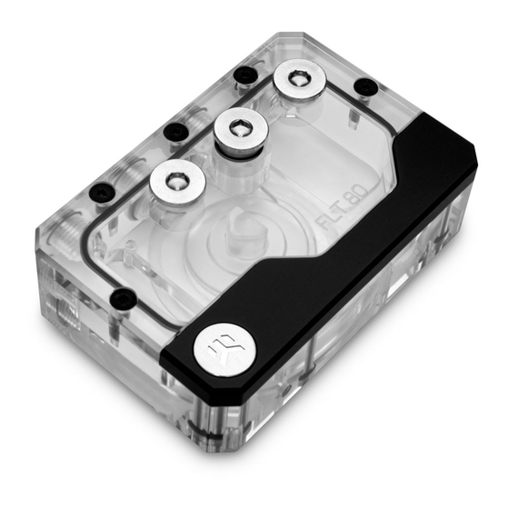
- Page 1 EK-Quantum Kinetic FLT 80 D5/DDC Body RESERVOIR USER GUIDE...
- Page 2 Before you start using this product, please follow these basic guidelines: Please carefully read the manual before beginning with the installation process! The EK fittings require only a small amount of force to screw them firmly in place since the liquid seal is ensured by the rubber o-ring gaskets.
-
Page 3: Table Of Contents
DDC PUMP VERSION ATTACHING THE DDC PUMP ON TO THE RESERVOIR INSTALLING EK-QUANTUM KINETIC FLT WITH SUPPLIED MOUNTS INSTALLING EK-QUANTUM KINETIC FLT USING UNI PUMP BRACKET ATTACHING EK-QUANTUM KINETIC FLT WITH SUPPLIED MOUNTS ATTACHING THE FITTINGS CONNECTING THE D-RGB LED STRIP... -
Page 4: Box Contents
Mounting Mechanism – You may not need every screw from this package. EAN: 102171 M4 x 8 DIN7984 Screw (4 pcs) M4 Nut (4 pcs) EK-Quantum Kinetic FLT 80 D5/DDC Body M4 x 10 DIN7984 Screw (4 pcs) PVC Washer M4 (4 pcs) EK-Loop Multi Allen Key (1 pc) Allen Key 2.5 mm (1 pc) -
Page 5: Reservoir Dimensions
RESERVOIR DIMENSIONS 52 mm 80 mm 14.5 mm 20 mm 36 mm - 5 -... -
Page 6: Technical Specifications And Product Parts
TECHNICAL SPECIFICATIONS AND PRODUCT PARTS Position EAN Description Quantity 100663 EK Badge 8312 M4 x 16 7991DIN Screw 103116 EK Plug G1/4 103773 Alu cover (Black) 100199 D-RGB LED Strip 103989 Top plexi plate 5092 OR 12 x 1.5 101921 OR 88 x 2 103772 Bottom plexi plate... -
Page 7: General Informations
GENERAL INFORMATIONS FLT Reservoir can be mount in multiple directions. Vertically and Do not mount FLT Reservoir when the pump is in dead position. horizontally position is optional. - 7 -... -
Page 8: D5 Pump Version
D5 PUMP VERSION ATTACHING THE D5 PUMP ON TO THE RESERVOIR PUMP HOLDER STEP 1 M4 x 20 DIN7984 Remove the preinstalled Pump Holder using 2.5 mm Allen Key. Store the screws and pump holder for later use. STEP 1 STEP 2 52 x 3 GASKET Make sure that the gasket (o- ring) is placed into the groove. -
Page 9: Ddc Pump Version
DDC PUMP VERSION ATTACHING THE DDC PUMP ON TO THE RESERVOIR M4 x 20 DIN7984 STEP 1 Remove the preinstalled Pump Holder and screws using 2.5mm PUMP HOLDER Allen Key. STEP 1 STEP 2 Carefully attach the DDC pump and make sure that gasket (46 x 2.5) is M4 x 25 DIN7984 placed correctly. -
Page 10: Installing Ek-Quantum Kinetic Flt With Supplied Mounts
INSTALLING EK-QUANTUM KINETIC FLT WITH SUPPLIED MOUNTS To enable installation of the reservoir where clearance for the pump D5 Version: is required, EK supplies a pair of FLT mounts along with M4 nuts, washers and additional screws. D5 MOUNT In case of using standard fan mounting location, only one supplied mount is required. - Page 11 STEP 2 D5 Version: Screw the mounts in place using supplied M4 x 8 screws and 2.5 mm allen key. M4 x 8 DIN7984 DDC Version: M4 x 8 DIN7984 STEP 2 - 11 -...
-
Page 12: Installing Ek-Quantum Kinetic Flt Using Uni Pump Bracket
INSTALLING EK-QUANTUM KINETIC FLT USING UNI PUMP BRACKET STEP 1 Position the bracket onto the reservoir and make sure that holes are aligned (as shown on the picture). Tighten the M4 x 8 DIN7984 Screws using M2.5 Allen Key. Tighten the screws evenly. - Page 13 Using 30 mm long screws supplied with your radiator the reservoir can be mounted onto the radiator and 25 mm thick fans together. UNC 6-32 x 30 ISO 7380 Screw Alternatively the shorter 5mm long screws from the radiator may be used to mount only the reservoir.
-
Page 14: Attaching The Fittings
M4 Washer M4 Nut M4 x 10 DIN7984 ATTACHING THE FITTINGS EK-Quantum Kinetic FLT has two inlet and two outlet ports, one of each must be used! INLET* FILL* All the unused ports should be blocked using G1/4 plugs! -
Page 15: Connecting The D-Rgb Led Strip
CONNECTING THE D-RGB LED STRIP STEP 1 Plug the 3-pin connector from Water block’s D-RGB LED light to the D-RGB HEADER on the motherboard. The LED will work if the pin layout on the header is as follows: +5V, Digital, empty, Ground. Please ensure that the arrow indicated on the connector is the plugged into the +5V line as indicated on your D-RGB HEADER... -
Page 16: Support And Service
SUPPORT AND SERVICE In case you need assistance or wish to order spare parts or a new mounting mechanism, please contact: https://www.ekwb.com/customer-support/ For spare parts orders, refer to the page with “TECHNICAL SPECIFICATIONS AND PRODUCT PARTS” where you can find the EAN number of each part you might need.
Need help?
Do you have a question about the Kinetic FLT 80 D5/DDC Body and is the answer not in the manual?
Questions and answers