Table of Contents
Advertisement
Quick Links
Advertisement
Table of Contents

Related Manuals for EK-Quantum Reflection2 PC-O11D XL D5 PWM D-RGB


Summary of Contents for EK-Quantum Reflection2 PC-O11D XL D5 PWM D-RGB
- Page 1 EK-Quantum Reflection PC-O11D XL D5 PWM D-RGB DISTRIBUTION PLATE USER GUIDE...
- Page 2 Before you start using this product please follow these basic guidelines: Please carefully read the manual before beginning with the installation process! The EK Fittings require only a small amount of force to screw them firmly in place since the liquid seal is ensured by the rubber O-ring gaskets.
-
Page 3: Table Of Contents
TABLE OF CONTENT BOX CONTENTS DISTRIBUTION PLATE DIMENSIONS TECHNICAL SPECIFICATIONS AND PRODUCT PARTS PREPARING THE 011D XL CHASSIS PREPARING AND INSTALLING THE DISTRIBUTION PLATE RECOMMENDED DISTRIBUTION PLATE CONFIGURATIONS ATTACHING THE PUSH-IN ADAPTER (OPTIONAL) CONNECTING THE D-RGB LED STRIP CONNECTING THE PUMP TESTING THE LOOP SUPPORT AND SERVICE SOCIAL MEDIA... -
Page 4: Box Contents
EK-Loop Multi Allen Key Screw M4 x 8 DIN7984 (2 pcs) M4 Nut (2 pcs) Allen Key 2.5 mm (1 pc) EK-Quantum Reflection PC-O11D XL D5 PWM D-RGB Allen Key 2 mm (1 pc) Replacement bottom Radiator bracket (1 pc) -
Page 5: Distribution Plate Dimensions
DISTRIBUTION PLATE DIMENSIONS 213.8 mm 161.8 mm 150.5 mm 77.8 mm 129.4 mm 44.4 mm 28.7 mm 106.1 mm 181.2 mm 51 mm 53.1 mm 109.1 mm 165 mm - 5 -... -
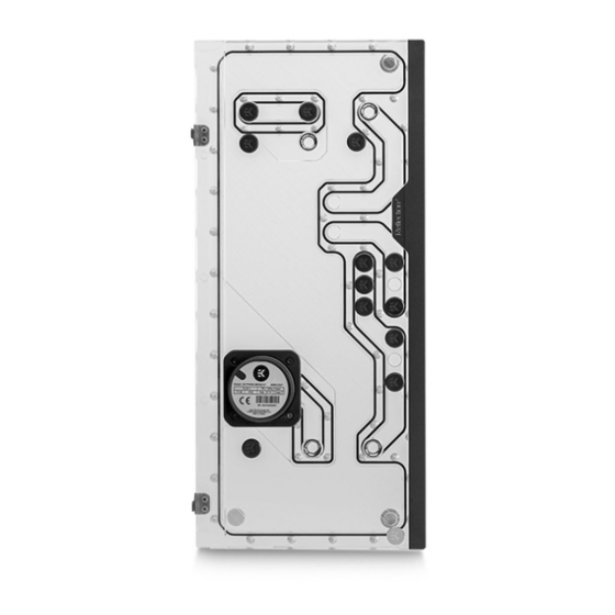
Page 6: Technical Specifications And Product Parts
TECHNICAL SPECIFICATIONS AND PRODUCT PARTS Technical Specification: Dimensions with the attached pump (W x D x H): 215.1 x 77.8 x 471.9 mm – D-RGB LED count: – D-RGB cable length: 500 mm – D-RGB connector standard 3-pin (+5V, Data, Blocked, Ground) Position Description Quantity... -
Page 7: Preparing The 011D Xl Chassis
PREPARING THE 011D XL CHASSIS Before installing the distribution plate, carefully read the PC case manual. STEP 1 Unscrew the factory provided screws and remove the top panel from the case. STEP 1 STEP 2 Remove both side panels and the front panel from the case. STEP 2 - 7 -... - Page 8 STEP 3 The SSD Trays also need to be removed from the back side of the chassis. Once the distribution plate is secured they can be reinstalled as required. STEP 3 STEP 4 Unscrew the 2(two) marked factory screws and remove the bottom Radiator bracket.
- Page 9 STEP 5 ORIGINAL From the original bottom Radiator bracket, remove two (2) marked BRACKET plastic tabs attached by four (4) cross pattern screws. Plastic tabs and screws reattach to the replacement bottom Radiator bracket and secure them with Philips head screwdriver. Tighten the screws evenly. After securing the distribution plate, replacement bottom Radiator bracket can be installed with the bottom radiator and fans.
-
Page 10: Preparing And Installing The Distribution Plate
For this step you will need: METAL PLATE Allen Key 2 mm STEP 1 STEP 2 Carefully place the EK-Quantum Reflection PC-O11D XL D5 PWM D-RGB distribution plate into the PC case and align the mounting holes. STEP 2 - 10 -... - Page 11 STEP 3 Secure the distribution plate to the chassis with two (2) M4 x 8 M4 NUT DIN7984 and M4 nuts (as shown in the diagram). SCREW M4 x 8 DIN7984 STEP 3 STEP 4 After the distribution plate is secured, the stored metal plate can be reattached using two (2) M3 x 18 DIN7991 Screws.
-
Page 12: Recommended Distribution Plate Configurations
RECOMMENDED DISTRIBUTION PLATE CONFIGURATIONS To complete your loop, all ports must be used as marked in the image. TOP RADIATOR OUTLET TOP RADIATOR OUTLET (DOUBLE RADIATOR (TRIPLE RADIATOR CONFIGURATION) CONFIGURATION) All remaining unused ports must be closed with supplied plugs, using the EK-Loop Multi Allen Key. - Page 13 FILL DRAIN - 13 -...
-
Page 14: Attaching The Push-In Adapter (Optional)
ATTACHING THE PUSH-IN ADAPTER (OPTIONAL) The push-in adapters can be attached to the marked places in the diagram. For easier installation of the push-in adapters, EK recommends to lubricate the O-rings with a few drops of coolant or water. - 14 -... -
Page 15: Connecting The D-Rgb Led Strip
CONNECTING THE D-RGB LED STRIP Plug the 3-pin connector of the distribution plate D-RGB LED light to the D-RGB HEADER on the motherboard. The LED will work if the pin layout on the header is as follows: +5V, Digital, Empty, Ground. D-RGB Header RGB Header CONNECTING THE PUMP... -
Page 16: Testing The Loop
TESTING THE LOOP To make sure the installation of EK components was successful, we recommend you perform a leak test for 24 hours. When your loop is complete and filled with coolant, connect the pump to a PSU outside of your system. Do not connect power to any of the other components. -
Page 17: Support And Service
SUPPORT AND SERVICE In case you need assistance or wish to order spare parts or a new mounting mechanism, please contact: https://www.ekwb.com/customer-support/ For spare parts orders, refer to the page with “TECHNICAL SPECIFICATIONS AND PRODUCT PARTS” where you can find the EAN number of each part you might need.
Need help?
Do you have a question about the Reflection2 PC-O11D XL D5 PWM D-RGB and is the answer not in the manual?
Questions and answers