EK-Quantum Reflection PC-O11D Mini D5 PWM D-RGB User Manual
Distribution plate
Hide thumbs
Also See for Reflection PC-O11D Mini D5 PWM D-RGB:
- User manual (16 pages) ,
- User manual (15 pages)
Table of Contents
Advertisement
Quick Links
Advertisement
Table of Contents

Related Manuals for EK-Quantum Reflection PC-O11D Mini D5 PWM D-RGB


Summary of Contents for EK-Quantum Reflection PC-O11D Mini D5 PWM D-RGB
- Page 1 EK-Quantum Reflection PC-O11D Mini D5 PWM D-RGB DISTRIBUTION PLATE USER GUIDE...
- Page 2 Before you start using this product please follow these basic guidelines: Please carefully read the manual before beginning with the installation process! The EK Fittings require only a small amount of force to screw them firmly in place since the liquid seal is ensured by the rubber O-ring gaskets.
-
Page 3: Table Of Contents
TABLE OF CONTENTS BOX CONTENTS DISTRIBUTION PLATE DIMENSIONS DISTRIBUTION PLATE SPECIFICATIONS AND MAIN PARTS PREPARING THE O11D Mini CHASSIS INSTALLING THE DISTRIBUTION PLATE IN THE O11D Mini RECOMMENDED DISTRIBUTION PLATE CONFIGURATIONS 7-SLOT CONFIGURATION 5-SLOT CONFIGURATION CONNECTING THE D-RGB LED STRIP CONNECTING THE PUMP TESTING THE LOOP SUPPORT AND SERVICE... -
Page 4: Box Contents
BOX CONTENTS M4 x 8 7991DIN (8 pcs) Allen Key 2.5 mm (1 pc) EK-Quantum Reflection PC-O11D Mini D5 PWM D-RGB EK-Loop Multi Allen Key - 4 -... -
Page 5: Distribution Plate Dimensions
DISTRIBUTION PLATE DIMENSIONS 206 mm 132 mm 8 mm 16.4 mm 134.6 mm 31.5 mm 77.3 mm - 5 -... -
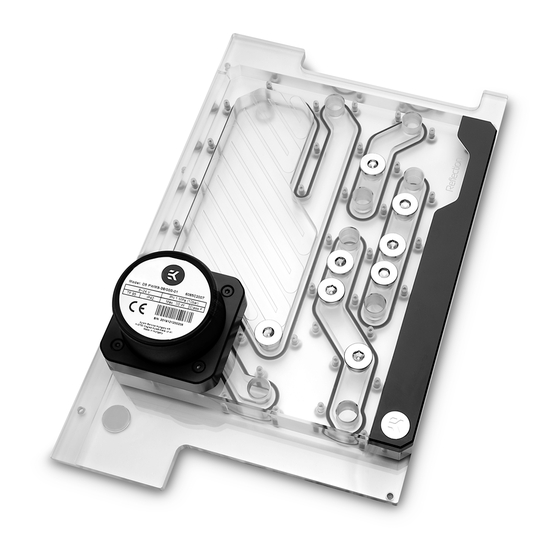
Page 6: Distribution Plate Specifications And Main Parts
DISTRIBUTION PLATE SPECIFICATIONS AND MAIN PARTS Technical Specification: • Technical Specification: - Dimensions (LxHxW): 206 x 332 x 77.3 mm M4 x 20 7984DIN SCREW • D-RGB (Addressable RGB) Cable Length: 500 mm • D-RGB LED Count: 14 • D-RGB Connector: Standard 3-Pin (+5V, Data, Blocked, Ground) D5 MOUNT (ACETAL) EK-RGB BADGE EK-D5 PWM... -
Page 7: Preparing The O11D Mini Chassis
PREPARING THE O11D Mini CHASSIS Before installing the distribution plate, carefully read the PC case manual. STEP 1 Unscrew the factory provided screws and remove the top panel from the case. FACTORY PROVIDED SCREWS STEP 1 STEP 2 Remove side and the front panel from the case. STEP 2 - 7 -... -
Page 8: Installing The Distribution Plate In The O11D Mini
INSTALLING THE DISTRIBUTION PLATE IN THE O11D Mini STEP 1 Carefully place the EK-Quantum Reflection PC-O11D Mini D5 PWM D-RGB - Plexi distribution plate into the PC case and align the mounting holes. STEP 1 STEP 2 Secure the distribution plate to the chassis with eight (8) M4 x 8 DIN7991 screws (as shown in the diagram). -
Page 9: Recommended Distribution Plate Configurations
RECOMMENDED DISTRIBUTION PLATE CONFIGURATIONS It is mandatory to use at least one of each type of port and all remaining ports should be sealed using the supplied plugs. The EK-Loop Multi Allen Key (6mm, 8mm, 9mm) may be used to install all EK fittings, do not use excessive force. - Page 10 FILL (EXTERIOR) DRAIN (EXTERIOR) RADIATOR 1 Up to SE360 (bottom) - 10 -...
-
Page 11: 5-Slot Configuration
5-SLOT CONFIGURATION ITX / mATX RADIATOR 3 (Optional) Up to SE360 (top) RADIATOR 2/3 OUT RADIATOR 2/3 IN CPU OUT/IN GPU IN/OUT (SLOT 1) RADIATOR 1 OUT DRAIN RADIATOR 1 IN RADIATOR 1 Up to SE360 (bottom) - 11 -... - Page 12 RADIATOR 3 (Optional) Up to SE360 (top) FILL (EXTERIOR) DRAIN (EXTERIOR) RADIATOR 1 Up to SE360 (bottom) - 12 -...
-
Page 13: Connecting The D-Rgb Led Strip
CONNECTING THE D-RGB LED STRIP Plug the 3-pin connector of the distribution plate D-RGB LED light to the D-RGB HEADER on the motherboard. The LED will work if the pin layout on the header is as follows: +5V, Digital, Empty, Ground. D-RGB Header RGB Header CONNECTING THE PUMP... -
Page 14: Testing The Loop
TESTING THE LOOP To make sure the installation of EK components was successful, we recommend you perform a leak test for 24 hours. When your loop is complete and filled with coolant, connect the pump to a PSU outside of your system. Do not connect power to any of the other components. -
Page 15: Support And Service
SUPPORT AND SERVICE For assistance please contact: http://support.ekwb.com/ EKWB d.o.o. Pod lipami 18 1218 Komenda Slovenia - EU SOCIAL MEDIA EKWaterBlocks @EKWaterBlocks ekwaterblocks EKWBofficial ekwaterblocks...
Need help?
Do you have a question about the Reflection PC-O11D Mini D5 PWM D-RGB and is the answer not in the manual?
Questions and answers