Table of Contents
Advertisement
Quick Links
Advertisement
Table of Contents

Related Manuals for EK-Quantum Kinetic FLT D5/DDC Body D-RGB


Summary of Contents for EK-Quantum Kinetic FLT D5/DDC Body D-RGB
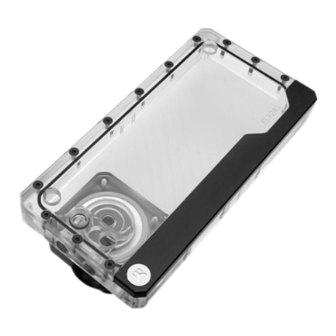
- Page 1 EK-Quantum Kinetic FLT D5/DDC Body D-RGB INSTALLATION MANUAL...
- Page 2 EKWB recommends any of the EK-Cryofuel for worry-free usage. There are many ways to install your EK-Quantum Volume/Kinetic FLT D5/DDC Body as it utilizes a standard fan mounting hole pattern with 15 mm spacing, the same as all EK radiators. The mounting holes have standard M4 threads with maximum engagement of 10 mm.
-
Page 3: Table Of Contents
D5 PUMP VERSION ATTACHING THE D5 PUMP ON TO THE RESERVOIR DDC PUMP VERSION ATTACHING THE DDC PUMP ON TO THE RESERVOIR INSTALLING EK-QUANTUM VOLUME / KINETIC FLT WITH SUPPLIED MOUNTS ATTACHING THE FITTINGS CONNECTING THE D-RGB LED STRIP TESTING THE LOOP... -
Page 4: Box Contents
M4 x 10 DIN7984 Screw (4 pcs) PVC Washer M4 (4 pcs) M4 x 25 DIN7984 Screw (4 pcs) EK-Quantum Kinetic FLT 120/240/360 D5/DDC Body DDC Mount (2 pcs) EK-Loop Multi Allen Key (1 pc) Allen Key 2.5 mm (1 pc) -
Page 5: Reservoir Dimensions
RESERVOIR DIMENSIONS 120 Version: 360 Version: 30 mm 30 mm 73.5 mm 46.5 mm 19.5 mm 46 mm 46.5 mm 73.5 mm 73.5 mm 120 mm 46.5 mm 240 Version: 30 mm 19.5 mm 46 mm 46.5 mm 73.5 mm 120 mm 73.5 mm 46.5 mm... -
Page 6: Technical Specifications And Product Parts
TECHNICAL SPECIFICATIONS AND PRODUCT PARTS 120 VERSION Technical Specification: - Dimensions: (L x H x W) – 120 x 120 x 46 mm - D-RGB cable length: 500 mm - D-RGB LED count: 6 - D-RGB connector standard 3-pin (+5V, Data, Blocked, Ground) Position EAN Description Quantity... -
Page 7: 240 Version
240 VERSION Technical Specification: - Dimensions: (L x H x W) – 120 x 240 x 46 mm - D-RGB cable length: 500 mm - D-RGB LED count: 14 - D-RGB connector standard 3-pin (+5V, Data, Blocked, Ground) Position EAN Description Quantity 102639... -
Page 8: 360 Version
360 VERSION Technical Specification: - Dimensions: (L x H x W) – 120 x 360 x 46 mm - D-RGB cable length: 500 mm - D-RGB LED count: 21 - D-RGB connector standard 3-pin (+5V, Data, Blocked, Ground) Position EAN Description Quantity 102639... - Page 9 FLT Reservoir can be mount in multiple directions. Do not mount FLT Reservoir when the pump is in dead position. Vertically and horizontally position is optional. - 9 -...
-
Page 10: D5 Pump Version
D5 PUMP VERSION ATTACHING THE D5 PUMP ON TO THE RESERVOIR M4 x 20 DIN7984 SCREW STEP 1: Remove the preinstalled Pump Holder using 2.5 mm Allen Key. Store the screws and pump holder for later use. PUMP HOLDER STEP 1 STEP 2: Make sure that the gasket (o- ring) is placed into the groove. -
Page 11: Ddc Pump Version
STEP 3 Carefully attach the D5 Pump and Pump Holder(as shown on the M4 x 20 DIN7984 photo). After that, secure all the parts together with M4 x 20 DIN SCREW 7984 Screws. Tighten the screws using enclosed 2.5 mm Allen Key. D5 PUMP HOLDER STEP 3... -
Page 12: Installing Ek-Quantum Volume / Kinetic Flt With Supplied Mounts
Tighten the screws using enclosed 2.5 mm Allen Key. PUMP STEP 2 INSTALLING EK-QUANTUM VOLUME / KINETIC FLT WITH SUPPLIED MOUNTS To enable installation of the reservoir onto fans, radiators or where clearance for the pump is required EK supplies a pair of FLT mounts along with M4 nuts, washers and additional screws. -
Page 13: Attaching The Fittings
M4 x 8 DIN 7984 SCREW STEP 2 ATTACHING THE FITTINGS EK-Quantum Kinetic FLT has two inlet and two outlet ports, one of each must be used! All 4 unused ports should be blocked using G1/4 plugs. FILL DRAIN... -
Page 14: Connecting The D-Rgb Led Strip
EK-Quantum Volume FLT has two ports which can be used as inlet or outlet, the chosen outlet should connect directly to your pump! The reservoir should be positioned above the pump to ensure it does not run without coolant. Both unused ports should be blocked using G1/4 plugs. -
Page 15: Testing The Loop
TESTING THE LOOP To make sure the installation of EK components was successful, we recommend you perform a leak test for 24 hours. When your loop is complete and filled with coolant, connect the pump to a PSU outside of your system. Do not connect power to any of the other components. -
Page 16: Support And Service
SUPPORT AND SERVICE In case you need assistance or wish to order spare parts or a new mounting mechanism, please contact: https://www.ekwb.com/customer-support/ For spare parts orders, refer to the page with “TECHNICAL SPECIFICATIONS AND PRODUCT PARTS” where you can find the EAN number of each part you might need.
Need help?
Do you have a question about the Kinetic FLT D5/DDC Body D-RGB and is the answer not in the manual?
Questions and answers