EK-Quantum Reflection PC-O11D XL D5 PWM D-RGB User Manual
Distribution plate
Hide thumbs
Also See for Reflection PC-O11D XL D5 PWM D-RGB:
- User manual (15 pages) ,
- User manual (16 pages)
Table of Contents
Advertisement
Quick Links
Advertisement
Table of Contents

Related Manuals for EK-Quantum Reflection PC-O11D XL D5 PWM D-RGB


Summary of Contents for EK-Quantum Reflection PC-O11D XL D5 PWM D-RGB
- Page 1 EK-Quantum Reflection PC-O11D XL D5 PWM D-RGB DISTRIBUTION PLATE USER GUIDE...
- Page 2 Before you start using this product please follow these basic guidelines: Please carefully read the manual before beginning with the installation process! The EK Fittings require only a small amount of force to screw them firmly in place since the liquid seal is ensured by the rubber O-ring gaskets.
-
Page 3: Table Of Contents
TABLE OF CONTENT BOX CONTENTS DISTRIBUTION PLATE DIMENSIONS TECHNICAL SPECIFICATIONS AND PRODUCT PARTS PREPARING THE 011D XL CHASSIS INSTALLING THE DISTRIBUTION PLATE IN THE 011D XL RECOMMENDED DISTRIBUTION PLATE CONFIGURATIONS CONNECTING THE D-RGB LED STRIP CONNECTING THE PUMP CONNECTING THE PUMP – MOLEX CONNECTOR CONNECTING THE PUMP –... -
Page 4: Box Contents
Mounting Mechanism – You may not need every screw from this package. EAN: 102558 EK-Loop Multi Allen Key M3x6 DIN7380 (2 pcs) M3x8 DIN7991 (5 pcs) M3 Nut (2 pcs) EK-Quantum Reflection PC-O11D XL D5 PWM D-RGB Allen Key 2mm (1 pc) Front mounting Bracket (1 pc) - 4 -... -
Page 5: Distribution Plate Dimensions
DISTRIBUTION PLATE DIMENSIONS 40 mm 33 mm 181.5 mm 37.5 mm 32.5 mm 106 mm 68.5 mm 148 mm 168 mm 215 mm - 5 -... -
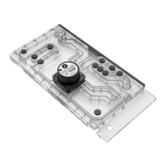
Page 6: Technical Specifications And Product Parts
TECHNICAL SPECIFICATIONS AND PRODUCT PARTS Position EAN Description Quantity 8311 M4 x 20 DIN7984 Screw 101803 Pump holder 100663 EK Badge 3831109837597 D5 Pump 5154 OR 52 x 3 8312 M4 x 16 DIN7991 Screw 102310 Top plexi 102303 OR Set 102309 Bottom plexi 102306... -
Page 7: Preparing The 011D Xl Chassis
PREPARING THE 011D XL CHASSIS Before installing the distribution plate, carefully read the PC case manual. STEP 1 Unscrew the factory provided screws and remove the top panel from the case. STEP 1 STEP 2 Remove both side panels and the front panel from the case. STEP 2 - 7 -... - Page 8 STEP 3 The SSD Trays also need to be removed from the back side of the chassis. Once the distribution plate is secured they can be reinstalled as required. STEP 3 STEP 4 For easier installation of the distribution plate, you should remove the Fan/SSD Tray from the bottom of the case.
-
Page 9: Installing The Distribution Plate In The 011D Xl
INSTALLING THE DISTRIBUTION PLATE IN THE 011D XL STEP 1 Carefully place the EK-Quantum Reflection PC-O11D XL D5 PWM D-RGB distribution plate into the PC case and align the mounting holes at the back. STEP 1 DETAIL VIEW STEP 2 Secure the distribution plate to the chassis with two (2) M3 x 6 DIN7380 and M3 nuts (as shown in the diagram). - Page 10 STEP 3 Position the front mounting bracket onto the distribution plate and secure it with five(5) M3 X 8 DIN7991 mounting screws. M3 X 8 DIN7991 Front mounting Bracket DETAIL VIEW M3 X 8 DIN7991 Front mounting Bracket STEP 3 - 10 -...
-
Page 11: Recommended Distribution Plate Configurations
RECOMMENDED DISTRIBUTION PLATE CONFIGURATIONS To complete your loop, all ports must be used as marked in the TOP RADIATOR INLET image. TOP RADIATOR OUTLET All remaining unused ports must be closed with supplied plugs, CPU OUTLET using the EK-Loop Multi Allen Key (6, 8, 9 mm). CPU INLET FILL Only one INLET and one OUTLET port for the GPU... - Page 12 FILL (exterior) DRAIN (exterior) - 12 -...
-
Page 13: Connecting The D-Rgb Led Strip
CONNECTING THE D-RGB LED STRIP Plug the 3-pin connector of the distribution plate D-RGB LED light to the D-RGB HEADER on the motherboard. The LED will work if the pin layout on the header is as follows: +5V, Digital, Empty, Ground. D-RGB Header RGB Header CONNECTING THE PUMP... -
Page 14: Connecting The Pump - Sata Connector
CONNECTING THE PUMP – SATA CONNECTOR The EK-D5 PWM pump has two connectors. 1. SATA Connector: It must be connected directly to your PSU at all times as it is used to power the pump. 2. 4-pin PWM fan: It can be connected to your motherboard’s CPU_ Fan or designated water pump header. -
Page 15: Support And Service
SUPPORT AND SERVICE In case you need assistance or wish to order spare parts or a new mounting mechanism, please contact: https://www.ekwb.com/customer-support/ For spare parts orders, refer to the page with “TECHNICAL SPECIFICATIONS AND PRODUCT PARTS” where you can find the EAN number of each part you might need.
Need help?
Do you have a question about the Reflection PC-O11D XL D5 PWM D-RGB and is the answer not in the manual?
Questions and answers