
Related Manuals for EK-Quantum Reflection2 V3000 Plus D5 PWM D-RGB Plexi


Summary of Contents for EK-Quantum Reflection2 V3000 Plus D5 PWM D-RGB Plexi
- Page 1 EK-Quantum Reflection V3000 Plus D5 PWM D-RGB - Plexi DISTRIBUTION PLATE USER GUIDE...
- Page 2 The installation of the product is intended to be undertaken by an adequately trained and experienced person. You are installing the product at your own risk. If you are not sufficiently trained or experienced or feel unsure about the installation procedure, please refrain from installing the product yourself and contact our tech support for assistance.
-
Page 3: Table Of Contents
TABLE OF CONTENT BOX CONTENTS DISTRIBUTION PLATE DIMENSIONS TECHNICAL SPECIFICATIONS AND PRODUCT PARTS PREPARING THE CHASSIS INSTALLING THE DISTRIBUTION PLATE RECOMMENDED DISTRIBUTION PLATE CONFIGURATIONS FLOW DIAGRAM CONNECTING THE D-RGB LED STRIP CONNECTING THE PUMP TESTING THE LOOP SUPPORT AND SERVICE SOCIAL MEDIA - 3 -... -
Page 4: Box Contents
BOX CONTENTS Mounting mechanism - Reflection V3000 Plus D5 PWM; EAN 106804 Allen Key 2.5 mm (1 pc) EK-Quantum Reflection V3000 Plus D5 PWM D-RGB - Plexi EK-Loop Multi Allen Key (1 pc) M4 0.8 mm Washer (8 pcs) Screw M4 x 5 DIN7984 (8 pcs) -
Page 5: Distribution Plate Dimensions
DISTRIBUTION PLATE DIMENSIONS 157.5 mm 136.5 mm 62.6 mm 34.6 mm 94.9 mm 49 mm 29.5 mm 108.5 mm 75.3 mm 88.3 mm - 5 -... -
Page 6: Technical Specifications And Product Parts
EK - Badge 100815 LED D-RGB strip 800/600 mm 102639 EK - Plug G1/4 3831109834282 EK-Quantum Torque Plug Cover - Black 106792 OR - V3000 Plus D5 PWM Set 8312 Screw M4 x 16 DIN7991 9051 Screw M4 x 25 DIN7991... -
Page 7: Preparing The Chassis
PREPARING THE CHASSIS Before installing the distribution plate, carefully read the TOP PANEL PC case manual. STEP 1 First, remove the PC case’s front panel. After that, you can remove the top and side panels. SIDE PANELS SIDE PANELS FRONT PANEL STEP 1 STEP 2 After removing the panels, the inner two (2) SSD plates (besides... -
Page 8: Installing The Distribution Plate
STEP 3 To functionally use the distribution plate to it’s full potential you also have to remove the two (2) drive cages. Note: If you will not use the side radiator configuration, one of the drive cages can still be inserted back into the case. STEP 3 INSTALLING THE DISTRIBUTION PLATE STEP 1... - Page 9 STEP 2 Secure the distribution plate from the backside using eight (8) M4X5 DIN7984 Screws and eight (8) M4 0.8 mm Washers with provided Allen Key 2.5 mm. For this step you will need: Allen Key 2.5 mm (1 pc) M4x5 DIN7984 Screw (8 pcs) M4 x 5 DIN7984 SCREW...
-
Page 10: Recommended Distribution Plate Configurations
RECOMMENDED DISTRIBUTION PLATE CONFIGURATIONS To complete your loop, all ports must be used as marked in the image. FILL TOP RADIATOR All remaining unused ports must be closed with supplied plugs, INLET using the EK-Loop Multi Allen Key. TOP RADIATOR OUTLET If one of the prescribed components will not be installed (ie. - Page 11 FILL DRAIN - 11 -...
-
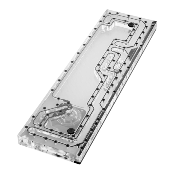
Page 12: Flow Diagram
FLOW DIAGRAM - 12 -... -
Page 13: Connecting The D-Rgb Led Strip
CONNECTING THE D-RGB LED STRIP Plug the 3-pin connector of the distribution plate D-RGB LED light to the D-RGB HEADER on the motherboard. The LED will work if the pin layout on the header is as follows: +5V, Digital, Empty, Ground. D-RGB Header RGB Header CONNECTING THE PUMP... -
Page 14: Testing The Loop
TESTING THE LOOP To make sure the installation of EK components was successful, we recommend you perform a leak test for 24 hours. When your loop is complete and filled with coolant, connect the pump to a PSU outside of your system. Do not connect power to any of the other components. -
Page 15: Support And Service
SUPPORT AND SERVICE In case you need assistance or wish to order spare parts or a new mounting mechanism, please contact: https://www.ekwb.com/customer-support/ For spare parts orders, refer to the page with “TECHNICAL SPECIFICATIONS AND PRODUCT PARTS” where you can find the EAN number of each part you might need.
Need help?
Do you have a question about the Reflection2 V3000 Plus D5 PWM D-RGB Plexi and is the answer not in the manual?
Questions and answers