Table of Contents
Advertisement
Quick Links
SITRANS F
Electromagnetic flowmeters
TRANSMAG 2 with MAG 911/E
Operating Instructions
03/2021
A5E00102775-AC
Introduction
Safety notes
Description
Installing/mounting
Connecting
Commissioning
Operating
Functions
Service and Maintenance
Troubleshooting
Technical specifications
Dimension drawings
Parameters
Profibus Communication
Product documentation and
support
1
2
3
4
5
6
7
8
9
10
11
12
A
B
C
Advertisement
Table of Contents

Related Manuals for Siemens SITRANS F TRANSMAG 2


Summary of Contents for Siemens SITRANS F TRANSMAG 2
- Page 1 Introduction Safety notes Description SITRANS F Installing/mounting Electromagnetic flowmeters TRANSMAG 2 with MAG 911/E Connecting Commissioning Operating Instructions Operating Functions Service and Maintenance Troubleshooting Technical specifications Dimension drawings Parameters Profibus Communication Product documentation and support 03/2021 A5E00102775-AC...
- Page 2 Note the following: WARNING Siemens products may only be used for the applications described in the catalog and in the relevant technical documentation. If products and components from other manufacturers are used, these must be recommended or approved by Siemens. Proper transport, storage, installation, assembly, commissioning, operation and maintenance are required to ensure that the products operate safely and without any problems.
-
Page 3: Table Of Contents
Table of contents Introduction ............................7 Purpose of this documentation .................... 7 History..........................7 Checking the consignment....................7 Items supplied ........................8 Designated use ........................8 Security information ......................8 Transportation and storage ....................9 Notes on warranty ....................... 9 Safety notes ............................ - Page 4 Table of contents Installing ferrite beads on unshielded cables............... 35 Step 1: Connecting power supply ..................35 Step 2: Connecting signal cables ..................36 Step 3: Connecting terminal box and transmitter ..............37 Commissioning ............................ 41 Operating TRANSMAG 2 ..................... 41 Write protection .........................
- Page 5 Table of contents Cyclic Data Traffic ......................107 Input Data (from Slave to Master)..................108 Status bytes ........................108 Output Data (from Master to Slave) .................. 111 Diagnostics ........................111 Write Protection ....................... 114 Device Database File (GSD) ....................114 Product documentation and support ....................
- Page 6 Table of contents TRANSMAG 2 with MAG 911/E Operating Instructions, 03/2021, A5E00102775-AC...
-
Page 7: Introduction
Introduction Purpose of this documentation These instructions contain all information required to commission and use the device. Read the instructions carefully prior to installation and commissioning. In order to use the device correctly, first review its principle of operation. The instructions are aimed at persons mechanically installing the device, connecting it electronically, configuring the parameters and commissioning it, as well as service and maintenance engineers. -
Page 8: Items Supplied
In a domestic environment this device may cause radio interference. Security information Siemens provides products and solutions with industrial security functions that support the secure operation of plants, systems, machines and networks. In order to protect plants, systems, machines and networks against cyber threats, it is necessary to implement –... -
Page 9: Transportation And Storage
The content reflects the technical status at the time of publishing. Siemens reserves the right to make technical changes in the course of further development. - Page 10 Introduction 1.8 Notes on warranty TRANSMAG 2 with MAG 911/E Operating Instructions, 03/2021, A5E00102775-AC...
-
Page 11: Safety Notes
Safety notes This device left the factory in good working condition. In order to maintain this status and to ensure safe operation of the device, observe these instructions and all the specifications relevant to safety. Observe the information and symbols on the device. Do not remove any information or symbols from the device. - Page 12 Material compatibility Siemens Flow Instruments can provide assistance with the selection of wetted sensor parts. However, the full responsibility for the selection rests with the customer and Siemens Flow Instruments can take no responsibility for any failure due to material incompatibility.
-
Page 13: Use In Hazardous Areas
Safety notes 2.3 Use in hazardous areas Use in hazardous areas Qualified personnel for hazardous area applications Persons who install, connect, commission, operate, and service the device in a hazardous area must have the following specific qualifications: • They are authorized, trained or instructed in operating and maintaining devices and systems according to the safety regulations for electrical circuits, high pressures, aggressive, and hazardous media. - Page 14 Safety notes 2.3 Use in hazardous areas TRANSMAG 2 with MAG 911/E Operating Instructions, 03/2021, A5E00102775-AC...
-
Page 15: Description
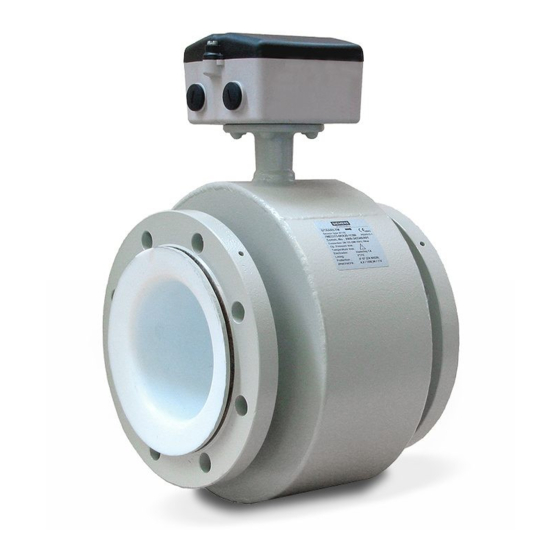
Description Overview SITRANS FM TRANSMAG 2 is a pulsed alternating field magnetic flowmeter where the magnetic field strength is much higher than conventional DC pulsed magnetic flowmeters. This makes it ideal for difficult applications as: • High concentrated paper stock > 3 % •... -
Page 16: Bus Communication
Description 3.3 BUS Communication • Slurry mode • Parameters can be specifically selected and modified, e.g.: – Operating parameters such as measuring range, physical dimensions or device information – Limits for flow, counter configurations – Noise suppression using separate interference suppression and damping as well as hysteresis functions –... -
Page 17: Theory Of Operation
Description 3.4 Theory of operation Theory of operation The flow measuring principle is based on Faraday’s law of electromagnetic induction. = When an electrical conductor of length L is moved at velocity v, perpendicular to the lines of flux through a magnetic field of strength B, the voltage U is induced at the ends of the conductor = L x B x v •... -
Page 18: Operating Principle
Description 3.5 Operating principle Operating principle SITRANS FM TRANSMAG 2 is a microprocessor-based transmitter with a built-in alphanumeric display in several languages. The transmitters evaluate the signals from the associated electromagnetic sensors and also fulfil the task of a power supply unit which provides the magnet coils with a constant current. -
Page 19: Installing/Mounting
Installing/mounting SITRANS F flowmeters with minimum IP65/NEMA 4X enclosure rating are suitable for indoor and outdoor installations. • Make sure that pressure and temperature specifications indicated on the device nameplate / label will not be exceeded. WARNING Installation in hazardous location Special requirements apply to the location and interconnection of sensor and transmitter. - Page 20 Installing/mounting 4.2 Sensor installation Figure 4-1 Correct installation with filled pipes • Avoid the following installations – Installation at the highest point in the pipe system – Installation in vertical pipes with free outlet Figure 4-2 Wrong installation at high point Figure 4-3 Correct installation at low point before outlet Inlet and outlet conditions...
- Page 21 Installing/mounting 4.2 Sensor installation TRANSMAG 2 with MAG 911/E Operating Instructions, 03/2021, A5E00102775-AC...
-
Page 22: Orienting The Sensor
Installing/mounting 4.2 Sensor installation 4.2.2 Orienting the sensor The sensor operates in all orientations, but Siemens has the following recommendations: • Vertical installation with an upwards flow Figure 4-4 Vertical orientation, upwards flow NOTICE Abrasive liquids / liquids containing solid particles... -
Page 23: Removing The Liner Protectors
Installing/mounting 4.2 Sensor installation 4.2.3 Removing the liner protectors NOTICE Sensors with PTFE or PFA liners only! The following information in only relevant for sensor types with PTFE or PFA liners! Sensors with PTFE liner At delivery the sensor is mounted with wooden blanks to hold the liner in place during transportation and storage. -
Page 24: Mounting
Installing/mounting 4.2 Sensor installation Sensors with PFA liner At delivery the sensor is mounted with blanks to protect the liner during transportation and storage. Figure 4-8 Sensor with blanks • Remove the blanks immediately before mounting the sensor Figure 4-9 Removing blanks NOTICE Do not use sharp objects to remove the blanks as this can damage the liner! - Page 25 Installing/mounting 4.2 Sensor installation • Use proper gaskets according to liner type. • If earthing rings are used, use standard flange gaskets on both sides of the ring. Figure 4-10 Correct installation with gaskets Figure 4-11 Inlet protection Vibrations In installations with strong vibrations remote installation of the transmitter is recommended. Alternatively mitigate vibrations by installing pipe support in close proximity to the flowmeter.
- Page 26 Installing/mounting 4.2 Sensor installation Figure 4-13 Pipe support variant 1 Figure 4-14 Pipe support variant 2 Mounting Fasten screws according to the torques values below Figure 4-15 Mounting Leakage/damage to flowmeter or piping may arise if bolts are overtightened. TRANSMAG 2 with MAG 911/E Operating Instructions, 03/2021, A5E00102775-AC...
-
Page 27: Potential Equalization
Installing/mounting 4.2 Sensor installation Torque calculations All values are theoretical and are calculated on the assumption that: • All bolts are new and material selection is according to EN 1515-1 table 2. • Gasket material not exceeding 75 shore A is used between the flowmeter and mating flanges. •... -
Page 28: Installation With Grounding Rings
Installing/mounting 4.2 Sensor installation Figure 4-17 Cathodic protection • Isolate the sensor from cathodic protected pipes using insulated bolts. • Use bypass cable between the mating flanges Note Remote mounted sensor versions If the above is not acceptable, remote mounted sensors can alternatively be connected as follows: •... - Page 29 Installing/mounting 4.2 Sensor installation Grounding strap connection on flat grounding rings Groundingstrap connection on type E grounding rings Note Abrasive liquids In special cases the grounding rings can work as inlet protection. NOTICE High temperature sensors High temperature sensors are delivered with two factory mounted grounding rings. No further action need to be taken for potential equalisation.
-
Page 30: Transmitter Installation
Installing/mounting 4.3 Transmitter installation Transmitter installation 4.3.1 Standard wall-mounting bracket Wall mounting 1. Fit the mounting bracket on the transmitter using the mounting material provided. 2. Mount transmitter with mounting plate on the wall. Figure 4-18 Standard wall-mounting bracket Note The standard wall-mounting bracket is only suitable for wall mounting. - Page 31 Installing/mounting 4.3 Transmitter installation Pipe mounting 1. Mount the assembly bracket on the pipe using the fastening brackets 2. Fasten the transmitter with the two screws provided. Pipe mounting with assembly bracket Wall mounting 1. Fasten the assembly bracket to the back of the transmitter 2.
-
Page 32: Turning The Local Display
Installing/mounting 4.4 Turning the local display Turning the local display The local display can be turned in 90° steps to enable better reading in case of vertical installation or overhead assembly. 1. Switch off the power supply. 2. Release the catch on the lid of the electronics compartment with a 3 mm Allen key. 3. -
Page 33: Connecting
Connecting General Information This chapter describes how to wire up the device. When using unshielded cables start by installing ferrite beads (Page 35). Afterwards: 1. Connect power supply (Page 35) 2. Connect signal cables (Page 36) 3. Connect terminal box and transmitter (Page 37) (must always be carried out) The chapter only describes wiring of devices with HART. - Page 34 Connecting 5.1 General Information WARNING The pertinent regulations must be observed for electrical installation. Never install the device with the mains voltage switched on! Danger of electric shock! The electrodes and magnetic current cables may only be connected when the device is not connected to the power supply.
-
Page 35: Installing Ferrite Beads On Unshielded Cables
Connecting 5.3 Step 1: Connecting power supply Installing ferrite beads on unshielded cables Usage of ferrite beads Ferrite beads are used to help reduce high-frequency interference on interface and control cables. Ferrite beads are only required when electromagnetic compatibility is an issue. When using shielded cables for inputs and outputs, ferrite beads are not needed. -
Page 36: Step 2: Connecting Signal Cables
Connecting 5.4 Step 2: Connecting signal cables Note Use cables with a cross section of at least 1.5 mm and double or reinforced insulation for the power supply. Wiring guidelines 1. Release the catch on the lid of the terminal box using a 3 mm Allen key. 2. -
Page 37: Step 3: Connecting Terminal Box And Transmitter
Connecting 5.5 Step 3: Connecting terminal box and transmitter 1. Push the signal cable through the cable gland up to the terminal strip. Lay the cable in a loop before the cable glands so that moisture does not get inside the terminal box. 2. - Page 38 Connecting 5.5 Step 3: Connecting terminal box and transmitter Preparing the cables Prepare the cable before connection as shown below. ① Connector sleeve ② Braided screen Figure 5-5 Preparation of the electrode and magnetic field current cable ① Lock nut ②...
- Page 39 Connecting 5.5 Step 3: Connecting terminal box and transmitter Connecting The sensor cable shield is connected to the transmitter and sensor as follows: 1. Bend the cable shield back over the clamping piece of the cable gland. 2. Push the clamping piece with the sensor cable into the threaded bush of the cable gland turning it slightly to the right.
- Page 40 Connecting 5.5 Step 3: Connecting terminal box and transmitter ① Electrode cable ② Magnetic current cable Figure 5-8 Power supply and signal cables Note Cable coloring on IP68 rated sensors With sensors with IP68 degree of protection, the cable colors or the identification tag on the sensor cables must be observed.
-
Page 41: Commissioning
Commissioning WARNING High voltage Certain parts inside the device carry dangerous high voltage. The housing must be closed and grounded before switching the device on. WARNING High pressure or corrosive media The sensor connected to this device can be operated with high pressure and corrosive media. Therefore improper handling of the device can lead to serious injuries and/or considerable material damage. - Page 42 Commissioning 6.1 Operating TRANSMAG 2 Operation via local display The device is operated with the optical elements on the local display. The elements are actuated by touching the glass panel above the appropriate operating element. The text display above the operating elements gives a menu-guided operation of the individual device functions/parameters.
- Page 43 Commissioning 6.1 Operating TRANSMAG 2 entered value is rejected, an error message briefly appears on the display and then the previous setting. You can then change it again. Note If the operating elements are kept actuated (with your finger continuously on the glass panel) the numeric value or setting option is changed continuously when using the tabular selection.
-
Page 44: Write Protection
Commissioning 6.3 Language and illumination Write protection The local display can be write-protected to prevent unauthorized manipulation by entering a freely selectable, personal code number. In this case the device functions and parameters can only be changed after entering this code. You define the personal code number in the "6.2 Customer code"... -
Page 45: Operating
Operating Operating examples Example 1: Changing engineering unit In the following example, the engineering unit for the current flow value is changed from m to l/min. The operating path to be executed is shown semibold in the diagram below. The operating elements to be actuated are specified and the individual operating steps numbered consecutively. - Page 46 Operating 7.1 Operating examples Function group 12.3 m3/h 1 display 5680 m3 Function group 2 Diagnostics Function group Measuring 3.1. Flow 3.1.1. Engr. Unit 3 Measuring functions Engr. Unit functions Flow 3.1.1 Engr. Unit l/min Measuring functions Totalizer forw. Measuring 3.3.
- Page 47 Operating 7.1 Operating examples 1. Enable the programming by pressing once. The unit in the second display line flashes 4.2.3 Unit lmp/l 1. Press once. Digit 1 flashes 4.2.3 Pulse rate +1.00 lmp./Unit 1. Change the digit from 1 to 2 by pressing once 4.2.3 Pulse rate...
- Page 48 Operating 7.1 Operating examples 4. 2. The currently valid setting appears in the display. u l s e r a t e Enable the programming. 4. 2. 3 U n i t The unit in the second display line m p / l flashes.
-
Page 49: Simatic Pdm
Operating Manual 'Help for SIMATIC PDM'. The manual is delivered with SIMATIC PDM software. Once the SIMATIC PDM is installed on your computer you find the manual under: Start > All programs > Siemens Automation > SIMATIC > Documentation. Link at our website: SIMATIC PDM instructions and manuals (https://support.industry.siemens.com/cs/ww/en/ps/... -
Page 50: Deactivate Buffers When Connecting Via Serial Modem
Operating 7.2 SIMATIC PDM 7.2.3 Deactivate buffers when connecting via serial modem Introduction This deactivation is required to align SIMATIC PDM with the HART modem when using a Microsoft Windows operating systems. Deactivating buffers is not necessary when connecting via USB. Condition •... -
Page 51: Updating The Electronic Device Description (Edd)
1. Check that the EDD revision match the Firmware revision in the device according to the table in section History (Page 7). 2. Go to the support page Software downloads (https://www.siemens.com/ processinstrumentation/downloads). 3. Enter the product name in the field "Enter search term...". - Page 52 Operating 7.2 SIMATIC PDM TRANSMAG 2 with MAG 911/E Operating Instructions, 03/2021, A5E00102775-AC...
-
Page 53: Functions
Functions Menu structure Operation is based on a hierarchically structured operating concept, i.e. all functions/ parameters are grouped logically and carry a menu code. The first (top) level is the main menu. You can select one of the following function groups: 1. -
Page 54: Function Group Diagnostics
Functions 8.3 Function Group Diagnostics Totalizer (menu item 1.4) Display of total flow This menu displays all totalizers which can all be reset together. These are: • Totalizer forwards, menu item 1.4.1 • Totalizer reverse, menu item 1.4.2 • Totalizer net, menu item 1.4.3 •... - Page 55 Functions 8.3 Function Group Diagnostics function for the digital outputs or ‘Failure signal’ for the analog output) (see menu items 4.1.2, 4.2.1 and 4.3.1). • A flashing "F" process related error at the top right of the display indicates a process error. •...
- Page 56 Functions 8.3 Function Group Diagnostics If the electrodes have no contact with the medium, the alarm signal "Tube empty" is triggered through the digital outputs. This alarm is also triggered in the case of an insulating coating on the electrodes. WARNING This message does not mean that the tube has actually run empty.
-
Page 57: Function Group Measuring Functions
Functions 8.4 Function Group Measuring Functions Function Group Measuring Functions Flow (Menu item 3.1) You have the following setting options in this menu: • Engineering unit, menu item 3.1.1 This function offers you the possibility of choosing between units of volume flow (volume unit per time unit) or mass flow (mass unit per time). - Page 58 Functions 8.4 Function Group Measuring Functions • Limits, menu item 3.1.3, consisting of: – Low Alarm Limit, menu item 3.1.3.1 and – High Alarm Limit, menu item 3.1.3.2 The input is made in absolute values within the sensor limits (depending on the nominal width, corresponding to -13 m/s to +13 m/s).
- Page 59 Functions 8.4 Function Group Measuring Functions • Density, menu item 3.1.4 You must specify unit and density here. The volume flow qv is converted to mass flow qm automatically using the formula (qm = qv * r). • Direction, menu item 3.1.5. This item is divided into: –...
- Page 60 Functions 8.4 Function Group Measuring Functions ① Reverse ② Forwards ③ Flow in % of range Figure 8-3 Hysteresis flow direction 1. Hysteresis (3.1.5.3). The limit values (menu items 3.1.5.1 and 3.1.5.2) can have a hysteresis added to prevent "fluttering" of the switching output. This setting is made in % of the set full scale value in the menu item 3.1.5.3 "Hysteresis".
- Page 61 Functions 8.4 Function Group Measuring Functions • Noise Suppress, menu item 3.1.7.3 This function serves to eliminate temporary, application-related interference within a fixed time frame. Every measured value within a measuring pulse is compared with the previously determined value. If it is outside the tolerance band set under menu item 3.1.7.3 (the specified % value refers to the set full scale value), the device operates with a filter time constant of 10 s.
- Page 62 Functions 8.4 Function Group Measuring Functions ① Flow in % with filter time constant ② Time Effect of a noise signal filter (example) Total. forwards (Menu item 3.2) You have the following setting options in this menu: • Set, menu item 3.2.1 In this menu you can reset the forwards totalizer to zero and restart if necessary.
- Page 63 Functions 8.4 Function Group Measuring Functions Total. reverse (Menu item 3.3) You have the following setting options in this menu: • Set, menu item 3.3.1 In this menu you can reset the reverse totalizer to zero and restart if necessary. If the totalizer overruns the optical display of the totalizer stops at "999999999"...
-
Page 64: Function Group Device Outputs
Functions 8.5 Function Group Device Outputs Function Group Device Outputs Analog out (Menu item 4.1) This menu only appears in devices with a 20 mA output (7ME5034-0xxxx and -2xxxx). The following settings are possible: • Current limiting, menu item 4.1.1 The upper current limit for the output signal is determined in this menu item. - Page 65 Functions 8.5 Function Group Device Outputs • Failure signal, menu item 4.1.2 In the event of a fault, e.g. a device error or measuring error due to entrapment of air, the analog output shows a predefined current. The following settings are possible: –...
- Page 66 Functions 8.5 Function Group Device Outputs 20mA ① Output current ② Split value ③ ④ Flow Figure 8-5 Split mode in domain 4 ... 20 mA Profibus (Menu item 4.1) This menu only appears in PROFIBUS devices. (7ME 5034-1xxxx). TRANSMAG 2 with MAG 911/E Operating Instructions, 03/2021, A5E00102775-AC...
- Page 67 Functions 8.5 Function Group Device Outputs This menu gives you the following setting options: • Bus address, menu item 4.1.1 The address 126 (factory setting) is reserved for newly connected devices and must be changed to a smaller value at the latest after commissioning on the bus. A value between 30 and 125 is recommended because addresses below 30 are only assigned for bus masters as a rule.
- Page 68 Functions 8.5 Function Group Device Outputs Digital output 1 (Menu item 4.2) You have the following setting options in this menu: • Function, menu item 4.2.1 You can configure digital output 1 as a pulse, frequency, alarm or status output When "Split value active"...
- Page 69 Functions 8.5 Function Group Device Outputs You can generate signals with positive and negative logic (positive and negative pulses). The figure below illustrates the setting options. • Pulse rate, menu item 4.2.3 The pulse valence indicates how many pulses are output per unit of volume or mass. When the "Pulse"...
- Page 70 Functions 8.5 Function Group Device Outputs When "Split value active" is selected, the output is active when the current level of the flow value is within the lower sub-domain 0 to "Split value". In this case the output current is scaled to the 0 to "Split value"...
-
Page 71: Function Group Identification
Functions 8.6 Function Group Identification Digital input (Menu item 4.3) The digital input is available with the device variant 7ME5034-2xxxx (Hart communication and digital input). You have the following setting options in this menu: • Function, menu item 4.3.1 By applying an external power supply, you can create a switching input, for example using a switch (see also Figure 5-12). - Page 72 Functions 8.6 Function Group Identification You can enter tag-specific data in these menu items. The operating elements take on the function of a cursor control here. The numbers, letters and text characters are selected with operating elements. If no text is stored, the end of text character flashes when opening these menu items.
-
Page 73: Function Group Service
Functions 8.7 Function Group Service The serial number and the order number of the device electronics are always displayed; in case of replaced electronics the latter is different from that of the device rating plate. • Nominal width, menu item 5.2.6.2 In this menu item you can set the nominal width in older generations of sensors manually if no SmartPLUG data are available. - Page 74 Functions 8.7 Function Group Service Control values (Menu item 6.5) These display values are for trained service personnel, since they are device-internal data mainly for error diagnosis. These include: • Magnet voltage Um, Uref, menu item 6.5.1 • Signal voltage Usig, menu item 6.5.2 •...
- Page 75 Functions 8.7 Function Group Service • ZPH, menu item 6.7.3 This is a factory-determined hydraulic calibration value at a flow of 0 m/s. This value is automatically taken from the SmartPLUG of the measuring sensor. For older measuring sensors without a SmartPLUG, the value must be transferred manually from the nameplate. •...
- Page 76 Functions 8.7 Function Group Service TRANSMAG 2 with MAG 911/E Operating Instructions, 03/2021, A5E00102775-AC...
-
Page 77: Service And Maintenance
• Seal integrity of the process connections, cable entries, and cover screws • Reliability of power supply, lightning protection, and grounds NOTICE Repair and service must be carried out by Siemens authorized personnel only. Note Siemens defines flow sensors as non-repairable products. -
Page 78: Ordering Of Spare Parts
Service and Maintenance 9.2 Ordering of spare parts Required forms • Delivery note • Return goods delivery note (https://www.siemens.com/processinstrumentation/ returngoodsnote) with the following information: – Product (item description) – Number of returned devices/replacement parts – Reason for returning the item(s) •... -
Page 79: Troubleshooting
If the measured values are too low, transmitter is defective. If the measured values are zero or with a wrong polarity, check cable leads. See also If the sensor or transmitter is defective, contact your local Siemens representative: Local contact person (http://www.automation.siemens.com/partner) TRANSMAG 2 with MAG 911/E... -
Page 80: Application Problems
Troubleshooting 10.2 Application Problems 10.2 Application Problems Table 10-1 Troubleshooting list Error Diagnosis Remedy Sensor does not work or no Power supply missing Connect or switch on power supply display or no output signal Device fuse defective Check device fuse and replace if necessary Transmitter does not react to Reflections in the glass Clean glass... - Page 81 Troubleshooting 10.2 Application Problems Error Diagnosis Remedy Measuring deviations, meas‐ Inlet and outlet lines insufficient Change installation (see Determining a location uring errors (Page 19)) Highly turbulent flow profile Change inlet line, use flow rectifier, reduce diam‐ eter of tube For mass measurement: medium density Correct density according to current medium set incorrectly...
-
Page 82: Error Messages
Troubleshooting 10.3 Error messages 10.3 Error messages Errors are indicated by a flashing "D" (Device error) or "F" (Measurement error) in the top right hand corner of the local display. Table 10-2 Error messages Error Diagnosis Remedy Flashing "D" in the top General device error (see also section Menu 2.1 Call device status right hand corner of the... - Page 83 Troubleshooting 10.3 Error messages Error Diagnosis Remedy Device status (menu 2.1) Measuring range overflow Reduce flow quantity or increase upper range val‐ "Measurement module ue in menu 3.1.2 failure" Device status (menu 2.1) Measuring electronics defective Measurement with reduced accuracy still possi‐ "Measurement module"...
- Page 84 Troubleshooting 10.3 Error messages TRANSMAG 2 with MAG 911/E Operating Instructions, 03/2021, A5E00102775-AC...
-
Page 85: Technical Specifications
Technical specifications Mode of operation Mode of operation and design Measuring principle Electromagnetic with pulsed alternating field (PAC) Magnetic field excitation Automatic power supply synchronization 50 Hz AC power supply • Bipolar 16.7 Hz • Bipolar with prepulse 10 Hz •... - Page 86 Technical specifications Outputs and inputs Outputs and Inputs Electrical isolation Outputs electrically isolated from each other and from the power supply, max. 60 V permissible against PE/ equipoten‐ tial bonding Current output 0/4 ... 20 mA (Only 20 mA / HART devices (7ME5034-0..and -2..)) Signal range Upper limit 0/4 ...
- Page 87 Technical specifications Outputs and Inputs Device profile 3.0; max. 4 simultaneous C2 connections Bus voltage Permissible 9 to 32 V Current consumption from bus 10 mA, limited to ≦ 15 mA in the event of an error by elec‐ trical current limitation Rated operating conditions Ambient temperatures Remote design...
- Page 88 Technical specifications Power supply Power supply AC voltage AC 100 to 250 V, ±15 %, 47 to 63 Hz Power consumption Approx. 120 to 630 VA, dependent on sensor Power failure Bridging of at least 1 power supply cycle (> 20 ms) Cable fuse AC 100 to 230 V: T1.6A Magnetic current fuse...
-
Page 89: Dimension Drawings
Dimension drawings Figure 12-1 SITRANS FM TRANSMAG 2 transmitter with standard wall-mounting bracket Figure 12-2 SITRANS FM TRANSMAG 2 transmitter with special wall-mounting bracket for pipeline mounting 131 (5.16) 155 (6.1) TRANSMAG 2 with MAG 911/E Operating Instructions, 03/2021, A5E00102775-AC... - Page 90 Dimension drawings Figure 12-3 SITRANS FM MAG 911/E sensor Table 12-1 Dimensions, nominal diameter DN 15 ... DN 100 Nominal diameter DN 15 DN 25 DN 40 DN 50 DN 65 DN 80 DN 100 ½" 1" 1½ 2" 2½" 3"...
- Page 91 Dimension drawings Table 12-3 Dimension, nominal diameter DN 450 ... DN 1000 Nominal diameter DN 450 DN 500 DN 600 DN 700 DN 750 DN 800 DN 900 DN 1000 18" 20" 24" 28" 30" 32" 36" 40" Built-in length 1040 1170 1300...
- Page 92 Dimension drawings TRANSMAG 2 with MAG 911/E Operating Instructions, 03/2021, A5E00102775-AC...
-
Page 93: Parameters
Parameters The device functions and parameters are listed below with the factory setting and setting option. The menu code only appears in the local display. Display Table A-1 Function group display parameters Menu code Device func‐ Description Factory setting Setting options tion, Parameters Display Param. - Page 94 Parameters Menu code Device func‐ Description Factory setting Setting options tion, Parameters Multi-Display Simultaneous display of two measuring var‐ (actual meas‐ • Menu 1.1.2 iables ured value line 1) • Menu 1.1.3 (actual meas‐ ured value line 2) Flow Flow value (actual meas‐...
- Page 95 Parameters 2.5.1 Flow Simulation of a flow value; affects all out‐ puts, totalizers, limit values and display. "F" flashes in the top right of the display during simulation and "Simulation" is dis‐ played under device status. Value Simulation value in % of full scale value -110% to +110% Time Duration of simulation...
- Page 96 Parameters Measuring functions Table A-3 Function group Measuring functions parameters Flow 3.1.1 Engr. Unit Engineering unit for volume flow or mass DN 2 ... 12: l/h • /s, m /min, m /h, m flow DN >12: m • l/s, l/min, l/h Note: •...
- Page 97 Parameters 3.1.5.1 Flow Direction Main flow direction related to direction ar‐ +Direction • +Direction, row on measuring tube (= forwards, posi‐ • -Direction tive flow values) 3.1.5.2 Meas.Direction Output of suppression of reverse flow forw.+rev. • forward only, Affects all outputs, totalizers and display •...
- Page 98 Parameters 3.3.2 Engr. Unit Engineering unit of volume DN 2...12: l • l, hl, m , Ml, ft , Gal, MGal, ImpGal, MImpGal DN >12: m • kg, t, g, lb Engineering unit of mass When you select a unit of mass, entry of the actual medium density is mandatory (menu 3.1.4) 3.3.3...
- Page 99 Parameters 4.1.4 Split mode The split mode divides the measuring range Inactive • Inactive into two domains: • Active • Domain 1 from 0 to ’Split value’ • Domain 2 from ’Split value’ to ’URV’ (upper range value, menu3.1.2) At digital outputs 1 or 2, it is possible to indicate whether the current measured val‐...
- Page 100 Parameters 4.2.5 Fullsc. Freq Frequency output at full scale flow value at 10000 Hz 2 ... 10000 Hz digital output 1 (only effective for "Frequen‐ cy" function) Digit.Output2 4.3.1 Function Assignment of a function to digital output 2 Alarm • Alarm, Flow dir.
- Page 101 Parameters 5.2.1 Product type Transmitter order number (7ME5034- xxxxx-xxA0) 5.2.2 Serial number Transmitter serial number (N1xxxx-82xxxx 5.2.3 Software Rev. Software version in the transmitter (3.x.x) 5.2.4 Device ID Clear device identification; (Device-specific 1 ... 99 999 (Can only be set HART long ad‐...
- Page 102 Parameters Control Values 6.5.1 Volt. Um Control value for magnetic field current Volt. Uref Control value for reference voltage 6.5.2 Volt. Usig Electrode differential voltage 6.5.3 Volt. Uel1 Control value for voltage between elec‐ trode 1 and medium 6.5.4 Volt. Uel2 Control value for voltage between elec‐...
- Page 103 Parameters 6.7.4 Excitat.Freq. Magnetic current curve: Bipolar PP • PP f/5 • Bipolar PP f/5: Standard applications • Bipolar f/3, • Bipolar f/3: rapid applications • Unipolar f/6 • Unipolar f/6: Measuring sensors ≦DN150 up to year of construction 1995 6.7.5 EmptyTube Det.
- Page 104 Parameters TRANSMAG 2 with MAG 911/E Operating Instructions, 03/2021, A5E00102775-AC...
-
Page 105: Profibus Communication
Profibus Communication PROFIBUS Communication The following functions of the standard device (with 20 mA/HART interface) are not offered in the PROFIBUS version (7ME5034-1xxxx) because they are covered indirectly by the PROFIBUS function: • Analog output (0/4 to 20mA) • HART communication •... -
Page 106: Wiring Devices With Profibus Pa
Profibus Communication B.2 Wiring devices with Profibus PA DP V1 services The following DP V1 services are supported as slaves for a class 2 master DP V1 services supported as slaves: • MSAC2_Initiate (Indication and Response) • MSAC2_Abort (Request, Indication and Response) •... -
Page 107: Cyclic Data Traffic
Profibus Communication B.3 Cyclic Data Traffic Shielding • Only use shielded cables for the PROFIBUS connection. Any connection polarity is possible. • The shield must be laid to cover all assigned terminal boxes, distributors up to the coupler or link. •... -
Page 108: Input Data (From Slave To Master)
Profibus Communication B.5 Status bytes The more than 300 parameters including address (Slot and Index), format, value range, start value and attributes are stored in an object list "Obj80C4.rtf" which will be provided on request. Note Acyclic operation with SIMATIC PDM We recommend using the SIMATIC PDM software package and a PC (compatible with industry standard) or a programming unit for acyclic operation. - Page 109 Profibus Communication B.5 Status bytes Table B-2 Status byte formats Byte 7 (MSB) 0 (LSB) Quality Substatus Limits These components may adopt the following values in SITRANS F: Table B-3 Formats of the quality bits Profile Designation Meaning Measured value cannot be used uncertain Measured value uncertain good (not cascade)
- Page 110 Profibus Communication B.5 Status bytes Profile Designation Meaning active advisory alarm Upper warning limit value has been exceeded or the lower warning limit value has been undershot below active critical alarm Upper alarm limit value has been exceeded or the low‐ er alarm limit value has been undershot Table B-5 Formats of the limit bits...
-
Page 111: Output Data (From Master To Slave)
Profibus Communication B.7 Diagnostics Meaning substatus applies to Value hex quality limits flow total net total total good active advisory alarm high limited good active advisory alarm low limited good active update event O.K. good O.K. O.K. Note The status conditions have decreasing priority from top to bottom. If several status conditions are fulfilled, the current status with the highest priority will be signaled. - Page 112 Profibus Communication B.7 Diagnostics If extended diagnostic messages (Ext_Diag_Data) exist, this is displayed by the "Diag_Flag" of the "Data_Exchange" service. If the master then calls the "Slave_Diag" service, the external diagnostic data are supplied in the following form by the device: Table B-8 Format of diagnostic data Byte...
- Page 113 Profibus Communication B.7 Diagnostics Bit No. Description Meaning Cause (local message) DIA_MEASUREMENT Measurement failure Flow measurement failure" "Tube empty" "Measuring range overflow" Table B-11 Format of diagnostic data, Byte 8 (=DIAGNOSIS Byte 4) Bit No. Description Meaning Cause (local message) 0 ...
-
Page 114: Write Protection
Profibus Communication B.9 Device Database File (GSD) Write Protection General write protection can be enabled with the WRITE_LOCKING PROFIBUS parameter. This will then prevent any changes being made to parameters locally or using PROFIBUS. • 0: General write protection enabled: Parameters cannot be edited. Exception: Output data for totalizers (set, start) when they are transmitted cyclically (with the data exchange service). - Page 115 These files are also implemented in the device install files for SIMATIC PDM software. GSD files (version 31.07.2001) #Profibus_DP GSD_Revision = 3 Vendor_Name = "SIEMENS AG" Model_Name = "SITRANS FM" Revision = "Revision 01" Ident_Number = 0x80C4 Protocol_Ident = 0...
- Page 116 Profibus Communication B.9 Device Database File (GSD) Bitmap_Device = "SIE80C4n" 31.25_supp = 1 45.45_supp = 1 93.75_supp = 1 MaxTsdr_31.25 = 100 MaxTsdr_45.45 = 250 MaxTsdr_93.75 = 1000 Redundancy = 0 Repeater_Ctrl_Sig = 0 24V_Pins = 0 Freeze_Mode_supp = 0 Sync_Mode_supp = 0 Auto_Baud_supp = 0 Set_Slave_Add_supp = 1...
- Page 117 Profibus Communication B.9 Device Database File (GSD) Unit_Diag_Bit(32) = "Zero point error" Unit_Diag_Bit(33) = "Power supply failed" Unit_Diag_Bit(34) = "Configuration invalid" Unit_Diag_Bit(35) = "Restart" Unit_Diag_Bit(36) = "Coldstart" Unit_Diag_Bit(37) = "Maintenance required" Unit_Diag_Bit(38) = "Characteristics invalid" Unit_Diag_Bit(39) = "Ident_Number violation" Unit_Diag_Bit(55) = "Extension Available" User_Prm_Data_Len = 0 ;=========== Description of modules =============================== ;...
- Page 118 Profibus Communication B.9 Device Database File (GSD) EndModule ;--------------------------------------------------------------------- ; Module 1 - Flow ;--------------------------------------------------------------------- Module = "Flow" 0x94 EndModule ;--------------------------------------------------------------------- ; Module 2 - Quantity net ;--------------------------------------------------------------------- Module = "Quantity net" 0x41, 0x84, 0x85 EndModule Module = "Resettable quantity net" 0xC1, 0x80, 0x84, 0x85 EndModule ;--------------------------------------------------------------------- ;...
- Page 119 Profibus Communication B.9 Device Database File (GSD) ;--------------------------------------------------------------------- ;SlotDefinition ;--------------------------------------------------------------------- SlotDefinition Slot(1) = "Flow" 1 0,1 ;Default am zykl. Verkehr Slot(2) = "Quantity net" 2 0,2,3 ;Default am zykl. Verkehr Slot(3) = "Quantity forward" 0 0,4,5 ;Default nicht am zykl. Verkehr Slot(4) = "Quantity reverse"...
- Page 120 Profibus Communication B.9 Device Database File (GSD) TRANSMAG 2 with MAG 911/E Operating Instructions, 03/2021, A5E00102775-AC...
-
Page 121: Product Documentation And Support
– "Download as html5, only PC": Open or save the manual in the HTML5 view on your PC You can also find manuals with the Mobile app at Industry Online Support (https:// support.industry.siemens.com/cs/ww/en/sc/2067). Download the app to your mobile device and scan the device QR code. Product documentation by serial number Using the PIA Life Cycle Portal, you can access the serial number-specific product information including technical specifications, spare parts, calibration data, or factory certificates. -
Page 122: Technical Support
Additional information on our technical support can be found at Technical Support (http:// www.siemens.com/automation/csi/service). Service & support on the Internet In addition to our technical support, Siemens offers comprehensive online services at Service & Support (http://www.siemens.com/automation/serviceandsupport). Contact If you have further questions about the device, contact your local Siemens representative at Personal Contact (http://www.automation.siemens.com/partner). -
Page 123: Index
Index Direction Flow, 59 Measurement, 59 Display, 53 Abrasive liquids, 22, 29 Disposal, 78 Acyclic data transmission, 107 Downloads, 121 Analog output, 64 Analog Output, 54 Applications, 15 Electrical connection Cable specifications, 34 Connection diagram, 36 Bus communication solutions, 16 HART, 37 Power supply, 35 Profibus, 106... - Page 124 Index Manufacturer data, 72 Material compatibility, 12 Measurement principle, 17 Measuring accuracy, 85 Gas / Air bubbles, 22 Menu structure, 53 grounding rings, 28 Modifications GSD, 114 correct usage, 12 improper, 12 Mounting, (See Installation) Multi display, 53 HART, 16 System integration, 43 Hazardous area Qualified personnel, 13...
- Page 125 Index Qualified personnel, 13 URV, (See Flow Upper Range Value) Reference conditions, 85 Vertical Pipes, 22 Repair, 77 Vibrations, 25 Reset, 73 Resistance, 79 Return procedure, 77 Warranty, 9 Wiring, (See Electrical connection) Write protection, 44 Safety, 11 Instrument safety standards, 11 Sensor installation, 19 Scope of delivery, 8 Zero flow correction, 74...
- Page 126 Index TRANSMAG 2 with MAG 911/E Operating Instructions, 03/2021, A5E00102775-AC...
Need help?
Do you have a question about the SITRANS F TRANSMAG 2 and is the answer not in the manual?
Questions and answers