Advertisement
Quick Links
Advertisement

Related Manuals for Body Solid Powerline PFT50


Summary of Contents for Body Solid Powerline PFT50
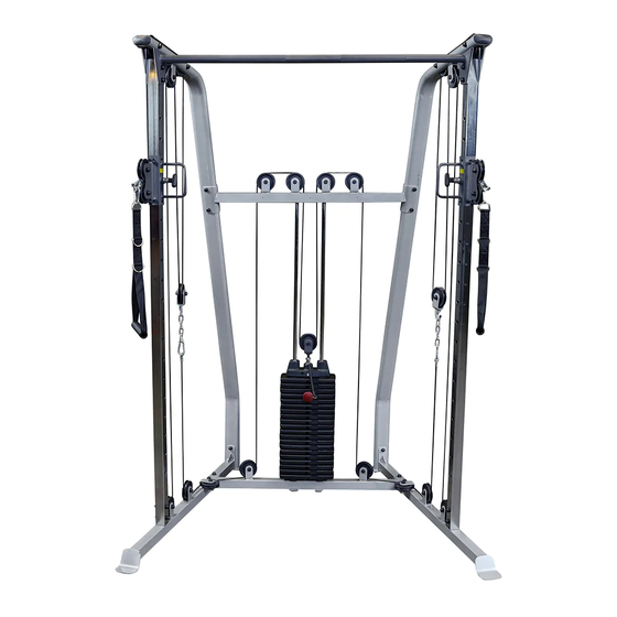
- Page 1 PFT50 FUNCTIONAL TRAINER Owner’s Manual WWW.BODYSOLID.COM V PFT50-20210218...
- Page 2 #DWRULE-4 #DWRULE-4...
-
Page 3: Table Of Contents
PFT50 TABLE OF CONTENTS • SAFETY INSTRUCTIONS....... PAGE 4 • PREPARATION........PAGE 5 • PART/HARDWARE LIST......PAGE 6 • HARDWARE ILLUSTRATION....PAGE 8 • ASSEMBLY INSTRUCTIONS....PAGE 23 • EXPLODED VIEW........PAGE 25 • CONTACT PAGE........PAGE 26... -
Page 4: Safety Instructions
PFT50 SAFETY INSTRUCTIONS The PFT50 is designed for your enjoyment. By follow- When using exercise equipment, ing these precautions and using common sense, you you should always take basic will have many safe and pleasurable hours of healthful precautions including the exercise with your Powerline Functional Trainer. following: After assembly, you should check all functions to • Read all instructions before using the PFT50. These ensure correct operation. If you experience problems, instructions are written to ensure your safety and to protect the unit. first recheck the assembly instructions to locate any possible errors made during assembly. If you are • Do not remove any safety labels from the unable to correct the problem, call the dealer from machine. • Do not allow children on or near the equipment. whom you purchased the machine or call 1-800-556- 3113 for the dealer nearest you. • Use the equipment only for its intended purpose as described in this guide. Do not use accessory attachments that are not recommended by the Obtaining Service manufacturer. Such attachments might cause serious Please use this Owner’s Manual to make sure that... -
Page 5: Preparation
PFT50 PREPARATION Required tools Assembly Tips The basic tools that you must obtain before assembling Read all “Notes” on each page before beginning each step. the PFT50 include but are not limit to: While you may be able to assemble the PFT50 using the • Standard Wrench Set illustrations only, important safety notes and other tips may be included in the text. • Metric Wrench Set Some pieces may have extra holes that you will not use. Use • Adjustable Wrench only those holes indicated in the instructions and illustrations. • Standard / Metric Allen Key Set NOTE: With so many assembled parts, proper alignment and adjustment is critical. While tightening the nuts and bolts, be sure to leave Installation Requirements room for adjustments. Follow these installation requirements when assembling the PFT50: NOTE: The bottles that are marked “Poison” is your touch up paint. Keep away from children. Set up the PFT50 on a solid, flat surface. A smooth, flat surface under the machine helps keep it level. CAUTION: Obtain assistance! If you feel like you can’t assemble the PFT50 by yourself then do Provide ample space around the machine. Open space not attempt to do so as this could result in around the machine allows for easier access. injury. Review the Installation Requirements before proceeding with the following steps. For aesthetic purposes, insert all bolts in the same direction unless specified (in text or illustrations) to do otherwise. -
Page 6: Part/Hardware List
PFT50 PART LIST Part # DESCRIPTION LEFT LOWER BEAM RIGHT LOWER BEAM BASE FRAME CHROME UPRIGHT LEFT UPRIGHT RIGHT UPRIGHT SUPPORT BEAM LAT BAR GUIDE ROD HANDLE DOUBLE PULLEY HOLDER SINGLE PULLEY HOLDER PULLEY BRACKET SELECTOR ROD PULL PIN BUSHING, 25X12.5X10mm BUSHING, 25x10.5x32mm CABLE, 7350mm CABLE, 6740mm... - Page 7 PFT50 PART LIST Part # DESCRIPTION M12x175mm HEX HEAD BOLT M10x45mm HEX HEAD BOLT M10x60mm HEX HEAD BOLT M10x70mm HEX HEAD BOLT M10x100mm HEX HEAD BOLT M8x10mm SET SCREW M6 ACORN CAP NUT M12 WASHER M10 WASHER M12 NYLON LOCK NUT M10 NYLON LOCK NUT TOP PLATE WEIGHT PLATE PIN...
-
Page 8: Hardware Illustration
PFT50 HARDWARE ILLUSTRATION Part #18 M12x177mm HEX HEAD BOLT QTY. 2 Part #19 M10x45mm HEX HEAD BOLT QTY. 21 Part #20 M10X60mm HEX HEAD BOLT QTY. 8 Part #21 M10X70mm HEX HEAD BOLT QTY.4... - Page 9 PFT50 HARDWARE ILLUSTRATION Part #22 M10X100mm HEX HEAD BOLT QTY.4 Part #24 M8X10mm SET SCREW QTY. 6 Part #26 M12 WASHER QTY. 4 ...
- Page 10 PFT50 HARDWARE ILLUSTRATION Part #28 M12 NYLON LOCK NUT QTY. 2 Part #29 M10 NYLON LOCK NUT QTY. 43 Part #31 M8x65mm HEX HEAD BOLT QTY. 2 ...
- Page 11 PFT50 HARDWARE ILLUSTRATION Part #35 M12 NUT QTY.1 Part #36 M12 LOCK WASHER QTY.1 Part #39 M10x45mm SOCKET HEAD CAP SCREW QTY. 1 Part #40 M10 LOCK WASHER QTY. 1 UNLESS OTHERWISE SPECIFIED: NAME DATE <CO UNLESS OTHERWISE SPECIFIED: NAME DATE <COMPANY NAME>...
- Page 12 PFT50 STEP 1 BE CAREFUL TO ASSEMBLE ALL COMPONENTS IN THE SEQUENCE THAT THEY ARE PRESENTED. NOTE: finger tighten all hardware. some components may be pre-assembled. 1A. Attach Left Lower Beam (A) to Base Frame (C) using: 2 - (#20) M10X60mm Hex Head Bolt 4 - (#27) M10 Washer 2 - (#29) M10 Nylon Lock Nut 1B.
- Page 13 PFT50 s T e P STEP 1 s T e P above shows step 1 assembled and completed LEFT RIGHT...
- Page 14 PFT50 STEP 2 BE CAREFUL TO ASSEMBLE ALL COMPONENTS IN THE SEQUENCE THAT THEY ARE PRESENTED. NOTE: finger tighten all hardware. some components may be pre-assembled. 2A. Attach Chrome UprightS (D) to Left & Right Lower Beams (A & B) using: 4 - (#20) M10X60mm Hex Head Bolt 8 - (#27) M10 Washer 4 - (#29) M10 Nylon Lock Nut...
- Page 15 s T e P PFT50 s T e P STEP 2 above shows step 2 assembled and completed LEFT RIGHT...
- Page 16 PFT50 STEP 3 BE CAREFUL TO ASSEMBLE ALL COMPONENTS IN THE SEQUENCE THAT THEY ARE PRESENTED. NOTE: finger tighten all hardware. some components may be pre-assembled. Install Guide Rods (Y) into the holes of the Base Frame (C). Install Rubber Donuts (#15) and slide to the bottom of the Guide Rods (Y) 3C.
- Page 17 PFT50 STEP 3 above shows step 3 assembled and completed...
- Page 18 PFT50 STEP 4 BE CAREFUL TO ASSEMBLE ALL COMPONENTS IN THE SEQUENCE THAT THEY ARE PRESENTED. NOTE: finger tighten all hardware FIRST. wrench tighten all hardware at the END of this step. some components may be pre-assembled. nylon lock nuts will not fully screw onto bolts, must wrench tighten. attach Lat Bar (H) to uprights (E &...
- Page 19 PFT50 STEP 4 above shows step 4 assembled and completed...
- Page 20 PFT50 STEP 5 BE CAREFUL TO ASSEMBLE ALL COMPONENTS IN THE SEQUENCE THAT THEY ARE PRESENTED. NOTE: finger tighten all hardware FIRST. wrench tighten all hardware at the END of this step. some components may be pre-assembled. nylon lock nuts will not fully screw onto bolts, must wrench tighten. 5A.
- Page 21 you’ll need to do is tighten the cables by stripping enough plastic coating on one side of the cable that is attached to one of the Handle Assemblies (J). Once their is no slack left, and the coating is stripped off secure the PFT50 cable by tightening the socket set screw (#24) that is pre-installed on Handle Assembly (J) on both the left and right side.
- Page 22 PFT50 STEP 6 BE CAREFUL TO ASSEMBLE ALL COMPONENTS IN THE SEQUENCE THAT THEY ARE PRESENTED. NOTE: finger tighten all hardware FIRST. wrench tighten all hardware at the END of this step. some components may be pre-assembled. nylon lock nuts will not fully screw onto bolts, must wrench tighten. 6A.
-
Page 23: Assembly Instructions
PFT50 STEP 6... - Page 24 PFT50 NOTE...
-
Page 25: Exploded View
PFT50 EXPLODED VIEW eXPlODeD View DiagRaM... -
Page 26: Contact Page
PFT50 please write your serial number in the boxes below 016194-��-��-����-���� S/N # 1900 S. Des Plaines Ave. Forest Park, IL 60130 Phone:(708)427-3555 Fax:(708)427-3556 Hours: M-F 8:30 - 5:00 CST...