Advertisement
Quick Links
Advertisement

Related Manuals for Body Solid Powerline PMP150


Summary of Contents for Body Solid Powerline PMP150
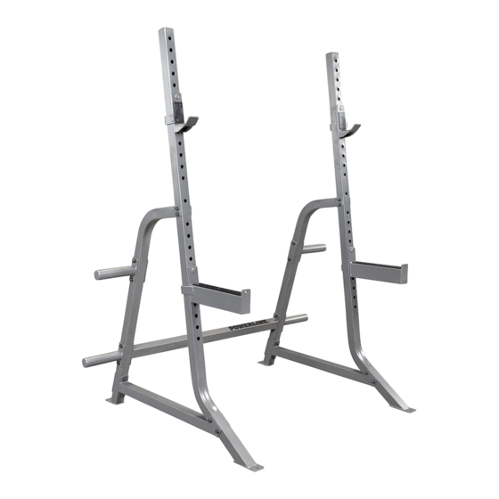
- Page 1 PMP150 MULTIPRESS RACK Owner’s Manual WWW.BODYSOLID.COM V PMP150-101518...
- Page 2 Do not allow the machine to be used until damaged or worn cables are replaced. Using or allowing a machine to be used with a suspect cable can result in serious injury. See Owner’s Manual for more information. For Body-Solid Customer Service Call 1-800-556-3113...
-
Page 3: Table Of Contents
PMP150 TABLE OF CONTENTS • SAFETY INSTRUCTIONS....... PAGE 4 • PREPARATION........PAGE 5 • PART/HARDWARE LIST......PAGE 6 • HARDWARE ILLUSTRATION....PAGE 7 • ASSEMBLY INSTRUCTIONS....PAGE 8 • EXPLODED VIEW........PAGE 15 • CONTACT PAGE........PAGE 16... -
Page 4: Safety Instructions
Powerline by Body Solid replacement parts when servicing this machine. Failure to do so will void your • Do no overexert yourself or work to exhaustion. warranty and could result in personal injury. • If you feel any pain or abnormal symptoms, stop your workout immediately and consult your physician. • Never operate unit when it has been dropped or For information about product operation or service, check out the official Powerline website damaged. Return the equipment to a service center for examination and repair. at www.bodysolid.com or contact an authorized • Never drop or insert objects into any opening in the Powerline dealer or a Powerline factory-authorized service company or contact Body-Solid customer equipment. service at one of the following: • Always check the unit and its cables before each use. Make sure that all fasteners and cables are secure Toll Free: 1-800-556-3113 and in good working condition. Phone: 1-708-427-3555 • Do not use the equipment outdoors or near water. Fax: 1-708-427-3556 Personal Safety During Assembly Email: service@bodysolid.com • Before beginning assembly, please take the time to Or write to: Body-Solid, Inc. -
Page 5: Preparation
PMP150 PREPARATION Required tools Assembly Tips The basic tools that you must obtain before assembling Read all “Notes” on each page before beginning each step. the PMP150 include but are not limit to: While you may be able to assemble the PMP150 using the • Standard Wrench Set illustrations only, important safety notes and other tips may be included in the text. • Metric Wrench Set Some pieces may have extra holes that you will not use. Use • Adjustable Wrench only those holes indicated in the instructions and illustrations. • Standard / Metric Allen Key Set NOTE: With so many assembled parts, proper alignment and adjustment is critical. While tightening the nuts and bolts, be sure to leave Installation Requirements room for adjustments. Follow these installation requirements when assembling the PMP150: NOTE: The bottles that are marked “Poison” is your touch up paint. Keep away from children. Set up the PMP150 on a solid, flat surface. A smooth, flat surface under the machine helps keep it level. CAUTION: Obtain assistance! If you feel like you can’t assemble the PMP150 by yourself then do Provide ample space around the machine. Open space not attempt to do so as this could result in around the machine allows for easier access. injury. Review the Installation Requirements before proceeding with the following steps. For aesthetic purposes, insert all bolts in the same direction unless specified (in text or illustrations) to do otherwise. -
Page 6: Part/Hardware List
PMP150 PART LIST Part # DESCRIPTION FRONT UPRIGHT SIDE CROSSMEMBER REAR UPRIGHT CENTER CROSSMEMBER WEIGHT HORN STEEL PLATE LEFT J-CUP RIGHT J-CUP RIGHT SPOTTER ARM LEFT SPOTTER ARM M10x75mm HEX HEAD BOLT M5x10mm FLAT HEAD CAP SCREW M10 WASHER M10 NYLON LOCKNUT PLASTIC PAD, 90x46mm PLASTIC PAD, 53x46mm PLASTIC PAD, 310x46mm... -
Page 7: Hardware Illustration
PMP150 HARDWARE ILLUSTRATION Part #1 M10x75mm HEX HEAD BOLT QTY . 20 Part #2 M5x10mm FLAT HEAD CAP SCREW QTY. 8 Part #3 M10 WASHER QTY. 40 ... -
Page 8: Assembly Instructions
PMP150 STEP 1 BE CAREFUL TO ASSEMBLE ALL COMPONENTS IN THE SEQUENCE THAT THEY ARE PRESENTED. NOTE: finger tighten all hardware FIRST. some components may be pre-assem- bled. 1A. attach Rear Uprights (C) to Center Crossmember (D) using: 4 - (#1) m10x75mm hex head bolt 8 - (#3) m10 flat washer 4 - (#4) m10 nylon lock nut 2 - ( E ) Weight Horn... - Page 9 PMP150 STEP 1 above shows step 1 assembled and completed...
- Page 10 PMP150 STEP 2 BE CAREFUL TO ASSEMBLE ALL COMPONENTS IN THE SEQUENCE THAT THEY ARE PRESENTED. NOTE: finger tighten all hardware FIRST. wrench tighten all hardware at the END of step 2C. some components may be pre-assembled. nylon lock nuts will not fully screw onto bolts, must wrench tighten. 2A.
- Page 11 PMP150 STEP 2 above shows step 2 assembled and completed...
- Page 12 PMP150 STEP 3 BE CAREFUL TO ASSEMBLE ALL COMPONENTS IN THE SEQUENCE THAT THEY ARE PRESENTED. NOTE: some components may be pre-assembled. nylon lock nuts will not fully screw onto bolts, must wrench tighten. 3A. attach Weight Horns (E) to Rear Uprights (C) using: 4 - (#1) m10x75mm hex head bolt 8 - (#3) m10 flat washer 4 - (#4) m10 nylon lock nut...
- Page 13 PMP150 STEP 3 above shows step 3 assembled and completed...
- Page 14 PMP150 NOTE...
-
Page 15: Exploded View
PMP150 EXPLODED VIEW... -
Page 16: Contact Page
PMP150 please write your serial number in the boxes below 014794-��-��-����-���� S/N # 1900 S. Des Plaines Ave. Forest Park, IL 60130 Phone:(708)427-3555 Fax:(708)427-3556 Hours: M-F 8:30 - 5:00 CST...
Need help?
Do you have a question about the Powerline PMP150 and is the answer not in the manual?
Questions and answers