
Related Manuals for Delta DPS Series


Summary of Contents for Delta DPS Series
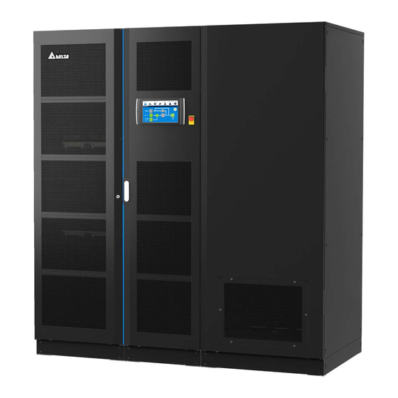
- Page 1 The power behind competitiveness Delta UPS - Modulon Family DPS Series, Three Phase 800/ 1000/ 1200 kVA User Manual www.deltapowersolutions.com...
- Page 2 Failure to heed these instructions and warnings will void the warranty. Copyright © 2021 by Delta Electronics Inc. All Rights Reserved. All rights of this User Manual (“Manual”), including but not limited to the contents, information, and figures are solely owned and reserved by Delta Electronics Inc.
-
Page 3: Table Of Contents
Table of Contents Chapter 1 : Important Safety Instructions ................7 Installation Warnings ................7 Connection Warnings ................7 Usage Warnings .................. 9 Storage Warnings ................11 Standard Compliance ............... 11 ... - Page 4 Bypass Mode Start-up Procedures ........... 91 6.2.4 Manual Bypass Mode Start-up Procedures ........91 6.2.5 ECO Mode Start-up Procedures ............93 6.2.6 Frequency Conversion Mode Start-up Procedures ......95 Ultron DPS Series...
- Page 5 Turn-off Procedures ................97 6.3.1 On-Line Mode Turn-off Procedures ..........97 6.3.2 Battery Mode Turn-off Procedures ............ 97 6.3.3 Bypass Mode Turn-off Procedures ........... 98 6.3.4 Manual Bypass Mode Turn-off Procedures ........98 ...
- Page 6 BMS Function on the LCD Screen ..........129 MFC Function on the LCD Screen ..........130 Chapter 9 : Maintenance ....................133 Appendix 1 : Technical Specifications ................134 Appendix 2 : Warranty ....................... 137 Ultron DPS Series...
-
Page 7: Chapter 1 : Important Safety Instructions
• Leave adequate space around all sides of the UPS for proper ventilation and maintenance. Please refer to 5.2 Installation Environment. • Only authorized Delta engineers or service personnel can perform installation and maintenance. If you want to install the UPS by yourself, please install it under the supervision of authorized Delta engineers or service personnel. - Page 8 4. The recommended electrical rating of the input, output and backfeed protective devices are as follows. Application of the protective devices shall be in accordance with local installation codes. 800kVA 1000kVA 1200kVA 690V/ 1600A 690V/ 2000A 690V/ 2500A Ultron DPS Series...
-
Page 9: Usage Warnings
(that have serious surge current) to the UPS, it needs to be de-rated according to on-site applications. For such special applications, please contact Delta service personnel for the accurate UPS sizing. The UPS is not suitable for connecting with any asymmetrical loads. For the load suitability, please contact Delta customer service before purchasing. - Page 10 5. Disconnect the charging source prior to connecting or disconnecting battery terminals. • You must contact Delta customer service if any of the following events occurs: 1. Any liquid is poured or splashed on the UPS. 2. The UPS is deformed.
-
Page 11: Storage Warnings
Storage Warnings • Use the original packing materials to pack the UPS to prevent any possible damage from rodents. • If the UPS needs to be stored prior to installation, it should be placed in a dry indoor area. The allowable storage temperature is below 70°C (158°F) and relative humidity is below 95%. -
Page 12: Chapter 2 : Introduction
Chapter 2 : Introduction General Overview The DPS series UPS, a three-phase four-wire online uninterruptible power supply (hereafter referred to as ‘UPS’), is a dedicated design for data centers, factory facilities and large scale power systems. The unit not only adopts advanced IGBT technology to provide high quality, low noise, pure and uninterruptible output power to the connected loads but also applies the latest design of DSP digital control technology and highest quality components. - Page 13 Item Q’ty 1 PC ❶ User Manual 1 PC ❷ Test Report 1 PC ❸ Snap Bushing 2 PCS ❹ Key (placed inside the UPS cabinet) 2 Copies ❺ USB Cable 1 PC ❻ Parallel Cable 1 PC ❼ Cable Tie (used for bundling and fixing the cables connected 18 PCS ❽...
- Page 14 M8 Screw (used for fixing the system cabinet and I/O cabinet 10 PCS ⓫ together) M12 Nut (used for input/ output/ battery wiring) 150 PCS ⓬ Flat Washer (used for input/ output/ battery wiring) 150 PCS ⓭ Ultron DPS Series...
- Page 15 Item Q’ty Rodent Shield (seven types A, B, C, D, E, F and G) 10 PCS ⓮ M5 Screw (used for fixing the rodent shields) 40 PCS ⓯ 4-Pin Dry Contact Terminal Block (used for REPO dry 1 PC ⓰ contacts) 6-Pin Dry Contact Terminal Block (used for MODBUS and 1 PC...
-
Page 16: Functions & Features
• Connects up to four external battery cabinets to extend backup time. • Provides setting options such as battery test (schedulable) and battery replacement alarm. • Battery temperature monitoring and compensation. Ultron DPS Series... -
Page 17: Exterior & Dimensions
• Optional battery management system (BMS) allows measurement of every battery’s voltage. • Smart battery charger design allows auto-charging or manual charging to shorten charging time. • Provides diversified communication interfaces and a SMART slot. Please refer to 4. Communication Interfaces. •... - Page 18 The power cabinet has already been connected with the system cabinet before shipment. Please follow 5.3 UPS Installation to join the system cabinet and the I/O cabinet together. (Figure 2-2: 1000/ 1200kVA UPS_ Exterior & Dimensions) Ultron DPS Series...
-
Page 19: Front View_ 800Kva
Front View_ 800kVA (Figure 2-3: 800kVA UPS_ Front View) (Figure 2-4: 800kVA UPS_ How to Open the Front Doors) -
Page 20: Front View_ 1000/ 1200Kva
Front View_ 1000/ 1200kVA (Figure 2-5: 1000/ 1200kVA UPS_ Front View of the I/O Cabinet) (Figure 2-6: 1000/ 1200kVA UPS_ Front View of the Power Cabinet & System Cabinet) Ultron DPS Series... - Page 21 (Figure 2-7: 1000/ 1200kVA UPS_ How to Open the Front Door of the I/O Cabinet) (Figure 2-8: 1000/ 1200kVA UPS_ How to Open the Front Doors of the Power Cabinet & System Cabinet)
-
Page 22: Internal View_ 800Kva
Internal View_ 800kVA WARNING: Only authorized Delta engineers or service personnel can perform installation, wiring, panel & cover removal, maintenance and operation. If you want to execute any action mentioned above by yourself, the action must be under the supervision of authorized Delta engineers or service personnel. - Page 23 (Figure 2-10: 800kVA UPS_ Wiring Terminals inside the I/O Cabinet) (Figure 2-11: 800kVA UPS_ Internal View of the System Cabinet)
-
Page 24: Internal View_ 1000/ 1200 Kva
5. The power outlet (220/ 230/ 240Vac, 3.15A) is without galvanic isolation. NOTE: Only authorized Delta engineers or service personnel can use the power outlet. If you want to use the power outlet by yourself, it must be under the supervision of authorized Delta engineers or service personnel. - Page 25 (Figure 2-13: 1000/ 1200kVA UPS_ Internal View of the I/O Cabinet) (Figure 2-14: 1000/ 1200kVA UPS_ Wiring Terminals inside the I/O Cabinet)
- Page 26 3. The power outlet (220/ 230/ 240Vac, 3.15A) is without galvanic isolation. NOTE: Only authorized Delta engineers or service personnel can use the power outlet. If you want to use the power outlet by yourself, it must be under the supervision of authorized Delta engineers or service personnel.
-
Page 27: Tri-Color Led Indicator & Buzzer
(Figure 2-16: 1000/ 1200kVA UPS_ Internal View of the Power Cabinet) For 1000kVA and 1200kVA power cabinets, their exteriors are the same. The main interior difference is the number of power cells. Please see the figure above. Tri-color LED Indicator & Buzzer (Figure 2-17: Tri-color LED Indicator Location) NOTE: For information about the 10”... - Page 28 The buzzer is located at the rear of the system cabinet’s front door. Please refer to the figures below. (Figure 2-18: 800kVA UPS_ Buzzer Location) (Figure 2-19: 1000/ 1200kVA UPS_ Buzzer Location) Ultron DPS Series...
- Page 29 Table 2-1: Tri-color LED Indicator, UPS Operation Mode & Buzzer Tri-color LED Status Meaning Indicator • Indicates the UPS is operating in one of the following modes. Text on the LCD Screen UPS Operation Mode (upper-right corner) Green On-Line Mode ‘On-Line’...
-
Page 30: Chapter 3 : Operation Modes
Bypass mode, Manual Bypass mode, ECO mode and Frequency Conversion mode. NOTE: 1. The UPS must be connected with an external maintenance bypass cabinet (user-supplied, handled and configured by Delta service personnel). For the external maintenance bypass cabinet’s information, please refer to 1.2 Connection Warnings. -
Page 31: Battery Mode
(Figure 3-1: On-Line Mode Diagram) Battery Mode The UPS transfers to Battery mode automatically if the main AC source is abnormal, for example, when unstable voltage or a power outage occurs. In Battery mode, the batteries provide DC power and the UPS converts it into AC power and supplies it to the connected critical loads via the external maintenance bypass cabinet’s Output Breaker or Switch (Q4). -
Page 32: Bypass Mode
DO NOT touch any external maintenance bypass cabinet’s terminal and bus bar which may carry high-voltage electricity. During Manual Bypass mode, the UPS’s input power is completely cut off, and the critical loads are not protected. At the moment, the UPS’s tri-color LED and LCD screen are both off. Ultron DPS Series... -
Page 33: Eco Mode
(Figure 3-4: Manual Bypass Mode Diagram) ECO Mode After the UPS is manually set as ECO mode via the LCD, the UPS will work in Bypass mode if bypass input voltage and frequency are within ±10% of the rated voltage and ±3Hz of the rated frequency respectively. -
Page 34: Frequency Conversion Mode
During Frequency Conversion mode, the UPS’s tri-color LED illuminates green and the text ‘Frequency Conversion’ appears in the upper right corner of the LCD screen. (Figure 3-6: Frequency Conversion Mode) Ultron DPS Series... -
Page 35: Chapter 4 : Communication Interfaces
Chapter 4 : Communication Interfaces The communication interfaces are hot-swappable and located at two different places. One is on the front of the system cabinet with its front door open and the other is at the rear of the touch panel. See Figure 2-11 and Figure 2-15 for their positions. Communication Interfaces (I): on the Front of the System Cabinet with Its Front Door Open (Figure 4-1: Communication Interfaces (I)) -
Page 36: Display Port
4.1.1 Display Port Before shipment, the display port has been connected to the 10” touch panel with the designated cable in Delta factory. 4.1.2 REPO Dry Contacts Connect the REPO dry contacts to a user-supplied switch and you can remotely shut down the UPS when an emergency occurs. -
Page 37: External Battery Temperature Dry Contacts
(Figure 4-4: Location of the Jump CNR3) 4.1.3 External Battery Temperature Dry Contacts You can use the external battery temperature dry contacts (BT1, BT2, BT3 and BT4) to detect a maximum of four external battery cabinets’ temperatures. You need to purchase the battery cabinet temperature sensor cable (optional). -
Page 38: External Switch/ Breaker Status Dry Contacts
NOTE: Only trained Delta engineers can enable the function. Please contact Delta customer service for implementation. (Figure 4-6: External Switch/ Breaker Status Dry Contacts) 4.1.5... - Page 39 (Figure 4-7: Output Dry Contacts & Schematic) Event Description None No set-up. Load On Inverter The UPS works in On-Line mode. Load On Bypass The UPS works in Bypass mode. When the main AC source fails, the batteries Load On Battery supply power to the critical loads.
- Page 40 When the UPS’s bypass SCR has a short- circuit issue, the UPS will send a signal to the Backfeed Protection connected external shunt trip device to cut off the backfeed voltage. When any UPS alarm occurs, the UPS will send General Alarm a signal. Ultron DPS Series...
-
Page 41: Input Dry Contacts
4.1.6 Input Dry Contacts There are four sets of programmable input dry contacts. The input dry contacts allow the UPS to receive external signals from peripheral devices and let the UPS response accordingly. Please use the touch panel to set each dry contact as normally open (NO) or normally closed (NC). - Page 42 If you use non-Delta lithium-ion batteries, you must set up Charger Off (Positive), Charger Off (Negative) and Charger Off these three items. Please refer to 7.6.6 Dry Contact Setting. For settings relevant to the non-Delta lithium- ion batteries, please refer to 7.6.4 Battery & Charging Setting. For more information, please contact Delta customer service.
-
Page 43: Parallel Communication Cards
Please refer to 5.4.4 Parallel Units Wiring to route the parallel cables. WARNING: One parallel cable is provided in each UPS’s accessory package. Using non-Delta parallel cables to parallel the UPSs may cause failure, malfunctions and accidents. (Figure 4-10: Location of the Parallel Ports) -
Page 44: Smart Slot
Please refer to 4.3 Cable Routing for the Communication Interfaces. 2. If you use the Delta lithium-ion batteries, you must install the optional multifunctional communication card (MFC) into the SMART slot to monitor the battery status. For settings and information relevant to the Delta lithium-ion batteries, please refer to 7.6.4 Battery &... -
Page 45: 4.1.11 Auxiliary Power Cards
4.1.11 Auxiliary Power Cards The UPS has two hot-swappable auxiliary power cards. Each card has one LED indicator. If the auxiliary power card works normally, its LED indicator will illuminate green. If the auxiliary power card is off or abnormal, its LED indicator will be off. WARNING: ... -
Page 46: Communication Interfaces (Ii): At The Rear Of The Touch Panel
Communication Interfaces (II): at the Rear of the Touch Panel (Figure 4-15: 800kVA UPS_ Communication Interfaces (II)) (Figure 4-16: 1000/ 1200kVA UPS_ Communication Interfaces (II)) Ultron DPS Series... - Page 47 Delta EnviroProbe 1000 (optional). Before shipment, the DISPLAY port has been ❹ DISPLAY connected. Connects to the Delta battery management system ❺ (optional). The BMS function is only applicable to lead- acid batteries. MODBUS 1. Provides MODBUS RTU communication service.
-
Page 48: Cable Routing For The Communication Interfaces
(❶). Fix the provided cable ties in the holes, use the cable ties to fix the cables connected to the communication interfaces (❷) and route the cables through the snap bushings (❸). (Figure 4-17: 800/ 1000/ 1200kVA UPS_ Top Cable Entry for the Communication Interfaces) Ultron DPS Series... - Page 49 Bottom Cable Entry for 800kVA UPS Open the 800kVA UPS’s front doors. Follow the figures below to fix the provided cable ties in the holes and use the cable ties to fix the cables connected to the communication interfaces (❶). Route the cables through the snap bushing (❷) and arrange the cables properly along the cabinet’s frame (❸).
- Page 50 1. Please follow local regulations to install a suitable conduit and bushing for cable protection. 2. Please refer to national and local electrical codes for acceptable cable sizes. 3. Only when 5.3 UPS Installation is completed can you perform wiring. Ultron DPS Series...
-
Page 51: Chapter 5 : Installation And Wiring
Delta engineers or service personnel. If you use a forklift or other equipment to move the UPS, please make sure its load bearing is sufficient. Please refer to Table 5-1. - Page 52 NOTE: Dust filters have been installed on the inner side of the UPS’s front doors before shipment. (Figure 5-1: 800kVA UPS_ Air Inlet & Outlet Direction) (Figure 5-2: 1000/ 1200kVA UPS_ Air Inlet & Outlet Direction) Ultron DPS Series...
-
Page 53: Ups Installation
WARNING: 1. Do not use air conditioners or similar equipment to blow into the rear of the UPS. 2. Do not hinder ventilation of the UPS. • Keep the installation area clean. Please note that wiring routes must be hermetic to prevent possible damage from rodents. - Page 54 Please firmly fix the stands which are at the bottom of the UPS on the ground to avoid UPS movement. Each stand requires a M12 expansion screw (provided by qualified service personnel). (Figure 5-4: 800kVA UPS_ Cabinet Floor Fixing Points) Ultron DPS Series...
- Page 55 (Figure 5-5: 1000/ 1200kVA UPS_ Cabinet Floor Fixing Points) (Figure 5-6: 800kVA UPS_ Fix the Stands on the Ground)
- Page 56 ( ❸ ) from the system cabinet’s internal panel, and use the provided eighty M10 screws and sixteen M12 screws to install the provided twelve connection bus bars ( ❹ ) as shown in the figure below. Ultron DPS Series...
- Page 57 (Figure 5-8: 1000/ 1200kVA UPS_ Install the Provided Connection Bus Bars)
- Page 58 UPS. After that, reinstall the removed panels and close the front doors. Step 7 After the steps above have been completed, please refer to 5.6 Installation of Rodent Shields to install the rodent shields. Ultron DPS Series...
-
Page 59: Wiring
UPS in the designated installation area firmly. 2. Before wiring, please read 5.4 Wiring thoroughly. 3. Only authorized Delta engineers or service personnel can perform installation, wiring, panel & cover removal, maintenance and operation. If you want to execute any action mentioned above by yourself, the action must be under the supervision of authorized Delta engineers or service personnel. - Page 60 M12/ 13 mm (0.51") Cable lug inner diameter TLAPH325- TLAPH325- TLAPH325- Terminal type* 2A12 2A12 2A12 Nominal discharge current (condition: 2V per 1754A 2193A 2632A cell) Battery Maximum discharge current (condition: 1.75V 2005A 2506A 3008A per cell) Ultron DPS Series...
- Page 61 UPS Capacity 800kVA 1000kVA 1200kVA 300 mm × 300 mm × 300 mm × Recommended (+/ -/ 6 PCS 7 PCS 8 PCS cable size (600 kcmil (600 kcmil (600 kcmil × 6 PCS) × 7 PCS) × 8 PCS) 300 mm ×...
- Page 62 2. The UPS will not work normally if the neutral (N) of the power sources (main/ bypass/ battery) is not properly connected to the UPS’s N terminals. 3. If the UPS is not grounded, the power boards and components might be damaged after the UPS is powered on. Ultron DPS Series...
-
Page 63: Single Input To Dual Input Modification
5.4.2 Single Input to Dual Input Modification NOTE: 1. Only authorized Delta engineers or service personnel can modify single input to dual input setup. 2. Please keep the removed components properly for future use. If you want to modify the UPS from dual input into single input, please use the removed screws and bus bars to connect the AC Input terminals (L1/ L2/ L3) and Bypass Input terminals (L1/ L2/ L3). -
Page 64: Single Unit Wiring
Before wiring, please read 5.4 Wiring thoroughly and make sure that relevant conditions have been met. Refer to Table 5-3 and Table 5-4 for information about the wiring terminals, breakers, switches and wiring. For the wiring diagrams and instructions, please refer to the following sections. Ultron DPS Series... - Page 65 Connect to the external maintenance bypass (L1/ L2/ L3/ N) cabinet’s output breaker or switch (Q4). Connect to the external battery cabinet(s). Please Battery Input Terminals contact Delta service personnel for battery (+/ -/ N) configurations. Connects to the external maintenance bypass PE (protective earth) cabinet’s GND terminal ( ).
-
Page 66: Single Input (Single Unit)
Step 2 Open the I/O cabinet’s front door and you will see the 800kVA UPS’s wiring terminals shown in Figure 2-9 ~ Figure 2-10 and 1000/ 1200kVA UPS’s wiring terminals shown in Figure 2- 13 ~ Figure 2-14. Ultron DPS Series... - Page 67 Step 3 A. For top wiring, please remove the top covers. (Figure 5-12: 800kVA UPS_ Location of the Top Covers) (Figure 5-13: 1000/ 1200kVA UPS_ Location of the Top Covers)
- Page 68 B. For bottom wiring, please remove the bottom covers. (Figure 5-14: 800kVA UPS_ Location of the Bottom Covers) (Figure 5-15: 1000/ 1200kVA UPS_ Location of the Bottom Covers) Ultron DPS Series...
- Page 69 Step 4 Make sure that the external maintenance bypass cabinet’s Input Breaker or Switch (Q1), Bypass Breaker or Switch (Q2), Manual Bypass Breaker or Switch (Q3) and the Output Breaker or Switch (Q4) are in the OFF position. Step 5 Make sure each external battery cabinet’s breaker (Q5) is in the OFF position.
- Page 70 M12 = 500 ± 10 kgf-cm (434 ± 8.7 lb-in) TLAPH325-2A12 Terminal Type* TLAPH325-2A12 TLAPH325-2A12 NOTE: The suggested manufacturer is K.S. TERMINALS INC. You may use equivalent terminals provided by other manufacturers. (Figure 5-17: Grounding Diagram_ Single Unit) Ultron DPS Series...
-
Page 71: Dual Input (Single Unit)
5.4.3.2 Dual Input (Single Unit) When there are two AC power sources, single unit wiring procedures are as follows. Step 1 Follow 5.4.2 Single Input to Dual Input Modification to modify the UPS from single input to dual input. Step 2 Follow Step 1 ~ Step 6 mentioned in 5.4.3.1 Single Input (Single Unit). -
Page 72: Parallel Units Wiring
Daisy Chain method shown in the figure below. For the parallel port location, refer to Figure 4-1. For top or bottom cable entry, refer to 4.3 Cable Routing for the Communication Interfaces. NOTE: One parallel cable is provided in each UPS’s accessory package. Ultron DPS Series... - Page 73 (Figure 5-19: Parallel Port Connection_ Daisy Chain Method) Step 3 Follow the table below to select proper Protective Earth (PE) cables to ground the parallel UPS units, external battery cabinet(s) and connected critical loads. The table is in accordance with IEC 60364-5-54 (Article 543 and Table 54.2). The grounding diagram below is for reference.
-
Page 74: External Battery Cabinet Connection Warnings
For relevant information, please refer to the manual of the lithium-ion batteries. 2. Whether you use the lead-acid batteries or the lithium-ion batteries, please contact Delta service personnel for any battery/ battery cabinet’s setup and configurations. WARNING: ... - Page 75 • To ensure that the batteries are fully charged, please charge the batteries for at least 8 hours before initial use of the UPS. The charging procedures are as follows. 1. (A) Connect the UPS to the external maintenance bypass cabinet (user-supplied) and external battery cabinet(s), and (B) connect the main AC source and bypass AC source (for dual input application only) to the external maintenance bypass cabinet.
- Page 76 A 4-pole DC circuit breaker connected in series with optional DC fuses A 3-pole DC circuit breaker connected in series with optional DC fuses For relevant values, please refer to Table 5-5. For installation diagrams, please refer to Figure 5-22 ~ Figure 5-25. Ultron DPS Series...
- Page 77 • The protective device is optional, and its type must be fast-acting DC circuit breaker and/ or fast-acting DC fuse. If you want to buy any of them, please contact Delta service personnel. When choosing the protective device, follow the instructions below.
- Page 78 For the actual maximum values, the maximum short-circuit capacity of the on-site batteries must be taken into consideration. Please contact Delta customer service for relevant information. External Battery Cabinet’s Protective Device (Option 1) (Figure 5-22: Installation of a 4-pole DC Isolated Switch Connected in Series with DC Fuses) External Battery Cabinet’s Protective Device (Option 2)
- Page 79 External Battery Cabinet’s Protective Device (Option 3) (Figure 5-24: Installation of a 4-pole DC Circuit Breaker Connected in Series with Optional DC Fuses) External Battery Cabinet’s Protective Device (Option 4) (Figure 5-25: Installation of a 3-pole DC Circuit Breaker Connected in Series with Optional DC Fuses)
- Page 80 For relevant information, please refer to the user manual of the lithium-ion batteries. Whether you use the lead-acid batteries or the lithium-ion batteries, please contact Delta service personnel for any battery/ battery cabinet’s setup and configurations. For common battery application, please install a protective device between each parallel UPS and its connected external battery cabinet(s).
- Page 81 (Figure 5-26: Common Battery Diagram)
-
Page 82: Installation Of Rodent Shields
To prevent possible damage from rodents, please install the rodent shields (provided) at the bottom of the UPS. 5.6.1 Installation of 800kVA UPS’s Rodent Shields Table 5-6: 800kVA UPS_ Rodent Shield Quantity Rodent Shield Type Quantity 3 PCS 3 PCS 2 PCS Ultron DPS Series... - Page 83 Step 1 Install the rodent shields A at the front bottom of the UPS. (Figure 5-27: 800kVA UPS_ Install the Rodent Shields A) Step 2 Install the rodent shields B at the rear bottom of the UPS. (Figure 5-28: 800kVA UPS_ Install the Rodent Shields B)
-
Page 84: Installation Of 1000/1200Kva Ups's Rodent Shields
(Figure 5-29: 800kVA UPS_ Install the Rodent Shields C) 5.6.2 Installation of 1000/1200kVA UPS’s Rodent Shields Table 5-7: 1000/ 1200kVA UPS_ Rodent Shield Quantity Rodent Shield Type Quantity 1 PC 1 PC 2 PCS 2 PCS 2 PCS 1 PC 1 PC Ultron DPS Series... - Page 85 Step 1 Install the rodent shields A, D and F at the front bottom of the UPS. (Figure 5-30: 1000/ 1200kVA UPS_ Install the Rodent Shields A, D & F)
- Page 86 Step 2 Install the rodent shields B, E and G at the rear bottom of the UPS. (Figure 5-31: 1000/ 1200kVA UPS_ Install the Rodent Shields B, E & G) Ultron DPS Series...
- Page 87 Step 3 Install the rodent shields C at the bottom of the two sides. (Figure 5-32: 1000/ 1200kVA UPS_ Install the Rodent Shields C)
-
Page 88: Chapter 6 : Ups Operation
4. The external battery cabinet’s breaker (Q5) shown on the LCD is always ON by default. To enable the detection of the Q5 status via the LCD, please contact Delta customer service for additional configurations. • Pre Start-up Warnings 1. Before UPS operation, ensure that installation and wiring have been completely done according to 5. -
Page 89: Start-Up Procedures
Pre Turn-off Warnings • Before you perform the turn-off procedures, please make sure the critical loads connected to the UPS have already been safely shut down. Start-up Procedures 6.2.1 On-Line Mode Start-up Procedures WARNING: Before turning on the UPS, please read 6.1 Pre Start-up & Pre Turn-off Warnings thoroughly and ensure that the precautions and instructions have been followed. -
Page 90: Battery Mode Start-Up Procedures
Switch ON the external maintenance bypass cabinet’s Output Breaker or Switch (Q4). Step 6 After the inverter turns on, the UPS will run in Battery mode, the LCD screen will show as below, and the tri-color LED indicator will illuminate yellow. Ultron DPS Series... -
Page 91: Bypass Mode Start-Up Procedures
6.2.3 Bypass Mode Start-up Procedures WARNING: Before turning on the UPS, please read 6.1 Pre Start-up & Pre Turn-off Warnings thoroughly and ensure that the precautions and instructions have been followed. Step 1 Ensure that the external maintenance bypass cabinet’s Manual Bypass Breaker or Switch (Q3) is in the OFF position. - Page 92 Switch ON the external maintenance bypass cabinet’s Input Breaker or Switch (Q1) and Bypass Breaker or Switch (Q2). After that, ensure that the bypass SCR is active. Step 3 Switch ON the external maintenance bypass cabinet’s Output Breaker or Switch (Q4). Ultron DPS Series...
-
Page 93: Eco Mode Start-Up Procedures
Step 4 After the UPS runs in Bypass mode, switch OFF the external maintenance bypass cabinet’s Manual Bypass Breaker or Switch (Q3). Step 5 Tap the ON/ OFF Button ( ) on the LCD screen. Step 6 After the inverter turns on, the UPS will run in On-Line mode, the LCD screen will show as below, and the tri-color LED indicator will illuminate green. - Page 94 After the inverter turns on and the system confirms that the bypass voltage is normal, the UPS will automatically transfer to ECO mode to let the bypass supply power, the LCD screen will show as below, and the tri-color LED indicator will illuminate green. Ultron DPS Series...
-
Page 95: Frequency Conversion Mode Start-Up Procedures
6.2.6 Frequency Conversion Mode Start-up Procedures WARNING: 1. Before turning on the UPS, please read 6.1 Pre Start-up & Pre Turn-off Warnings thoroughly and ensure that the precautions and instructions have been followed. 2. Frequency Conversion mode is only applicable to single UPS but not to parallel UPSs. - Page 96 After the inverter turns on, the UPS will run in Frequency Conversion mode, the output frequency will be the same as the setup value, the LCD screen will show as below, and the tri- color LED indicator will illuminate green. Ultron DPS Series...
-
Page 97: Turn-Off Procedures
Turn-off Procedures 6.3.1 On-Line Mode Turn-off Procedures WARNING: Before turning off the UPS, please read 6.1 Pre Start-up & Pre Turn-off Warnings thoroughly and ensure that the precautions and instructions have been followed. Step 1 Tap the ON/ OFF Button ( ) to shut down the UPS’s inverter. -
Page 98: Bypass Mode Turn-Off Procedures
Tap the ON/ OFF Button ( ) to shut down the UPS’s inverter. After that, the UPS will let the bypass AC source supply power. At the moment, if the bypass is abnormal, there is a risk of output interruption. Ultron DPS Series... -
Page 99: Frequency Conversion Mode Turn-Off Procedures
Step 2 Switch OFF the external maintenance bypass cabinet’s Input Breaker or Switch (Q1), Bypass Breaker or Switch (Q2), and Output Breaker or Switch (Q4). After that, the UPS will transfer to Standby mode. Step 3 Wait for the UPS to complete the DC BUS discharging. After that, switch OFF each external battery cabinet's breaker (Q5), and the LCD and tri-color LED indicator will be off. - Page 100 Ensure that the output voltage difference between each parallel UPS is below 3V. Only authorized Delta engineers or service personnel can check the output voltage difference, or it must be done under the supervision of authorized Delta engineers or service personnel. Step 5 Now, the UPSs are ready to operate in parallel.
-
Page 101: Chapter 7 : Lcd Display & Settings
Chapter 7 : LCD Display & Settings LCD Display Hierarchy Please refer to Figure 7-1 for an overview of all the LCD items. For some of the items marked with an asterisk, they will show up only under certain conditions. Please refer to the note below for details. - Page 102 Ultron DPS Series...
- Page 103 (Figure 7-1: LCD Display Hierarchy)
-
Page 104: How To Turn On The Lcd
To display the item(s), you have to log in as Administrator. Please refer to 7.4 Password Entry. The item(s) will show up only when you use the Delta lithium-ion batteries and have installed the optional multifunctional communication card (MFC) in the SMART slot. -
Page 105: Introduction Of Touch Panel And Function Keys
Introduction of Touch Panel and Function Keys... - Page 106 Indicates User login status. Tap the icon to change the login permission. Please refer to 7.4 Password Entry. Indicates Administrator login status. Tap the icon to change the login permission. Please refer to 7.4 Password Entry. Ultron DPS Series...
- Page 107 Text/ Button Symbol Digital Function Display Icon/ Text Display Description (Yes or (Yes or (Yes or 1. Historical event screen shortcut button ( 2. When the icon is blue ( ), it means there is no warning event. 1.
- Page 108 1. Indicates battery status (Green: Normal/ Flashing Green & Gray: Battery Mode/ Flashing Red & Gray: Battery Not Connected). 2. Shows battery remaining capacity (%) and battery remaining time (minutes). 3. Battery status screen shortcut button. Ultron DPS Series...
- Page 109 Text/ Button Symbol Digital Function Display Icon/ Text Display Description (Yes or (Yes or (Yes or Indicates bypass static switch status (Green: ON/ Gray: Abnormal or OFF). Indicates rectifier status (Green: Normal/ Gray: Waiting or OFF). 1. Indicates inverter status (Green: Normal/ Gray: Waiting or OFF).
-
Page 110: Password Entry
→ enter the Administrator password (contact service personnel for the default password) → the icon appears, indicating the Administrator login is successful. 3. To change the Administrator password, please go to → General Setting → User → Admin Password (4 digits). Ultron DPS Series... -
Page 111: Check Kilowatt-Hour
Check Kilowatt-Hour Path: → Main Input → kWh icon ( Tap the kWh icon ( ), and you can check the kWh statistics of the UPS main input in the following window. -
Page 112: Ups Settings
Set up the bypass output’s frequency range. Bypass Voltage (Max.) Set up the bypass output’s maximum voltage. Bypass Voltage (Min.) Set up the bypass output’s minimum voltage. Set up the bypass output’s voltage range in ECO mode. ECO Voltage Range Ultron DPS Series... -
Page 113: Mode Setting
7.6.2 Mode Setting Path: → Mode Setting Item Description Set up the UPS in On-Line mode. In On-Line mode, it is the On-Line Mode inverter to supply power to the connected loads. Set up the UPS in ECO mode. In ECO mode, it is the bypass to supply power to the connected loads. -
Page 114: Battery & Charging Setting
If you use the Delta lithium-ion batteries, please set up the battery type as 'LiB (Integration)'. The item 'LiB (Integration)' will appear on the LCD only if you use the Delta lithium-ion batteries with the optional multifunctional communication card (MFC) being installed in the SMART slot. Please contact Delta customer service if you need more information. - Page 115 Item Description Set up the battery low voltage. In Battery mode, when the battery low voltage is reached, the battery power will be cut Battery Cut Off off, and the inverter of the UPS will shut down. The loads will Voltage then be transferred to bypass if the bypass is available;...
-
Page 116: Parallel Setting
2. Generator Status (normally open) or Input Dry Contact 2 3. Battery Ground Fail NC (normally Input Dry Contact 3 closed) for each 4. External Battery Breaker Detection Input Dry Contact 4 input dry contact. 5. Charge Off (Positive) Ultron DPS Series... - Page 117 Input Dry Event Selection Type Contact No. 6. Charge Off (Negative) Input Dry Contact 1 7. Active Standby Set up NO Input Dry Contact 2 8. Battery Abnormal Shutdown (normally open) or 9. Input Transformer OTW NC (normally Input Dry Contact 3 closed) for each Input Dry Contact 4 10.
-
Page 118: General Setting
Set up the MODBUS mapping table (default: Table MODBUS Mapping Table Table A: Compatible with Delta MODBUS card. Table B: Applicable to DPS Gen2 MODBUS. Dust Filter If you have installed any dust filter, please select 'Enable';... -
Page 119: Ip Setting
Item Sub Item Description DUST NOTE: FILTER Dust Filter Only when you select 'Enable' for 'Dust Replacement Date (Con- Filter Installation' can you set up the item. tinued) 7.6.8 IP Setting Path: → IP Setting Item Description DHCP Client Enable or disable the DHCP client. IP Address Set up the IP address. -
Page 120: System Maintenance
Path 1: → Warning Path 2: When there is a warning, the buzzer icon ( ) will light up in red, and the buzzer will sound. Tap the warning icon ( ) to enter the WARNING screen. Ultron DPS Series... -
Page 121: Historical Event
7.7.2 Historical Event Path: → Historical Event 7.7.3 Statistics Path: → Statistics Item Description In Battery Mode Shows how long and how many times the UPS runs in Battery mode. In Bypass Mode Shows how long and how many times the UPS runs in Bypass mode. Operation Time Shows how long the UPS has operated. -
Page 122: Advanced Diagnosis
7.7.6 Advanced Diagnosis Path: → Advanced Diagnosis This is an optional function. If you would like to access this page, please contact Delta customer service. 7.7.7 Version & S/N NOTE: To operate the UPSs in parallel, please make sure all the versions below are the same for each parallel unit. - Page 123 Item Sub Item Description Check and update the MCU version of a specific PM #_ MCU power module’s CHG.
-
Page 124: Chapter 8 : Optional Accessories
LCD Screen and 7.6.4 Battery & Charging Setting. System (BMS) NOTE: The quantity of BMS to be installed depends on how many external battery cabinets (lead-acid batteries) are connected to the UPS. For BMS installation, please contact Delta customer service. Ultron DPS Series... -
Page 125: Ems Function On The Lcd Screen
Item Function If you use the Delta lithium-ion batteries, you must purchase and install the multifunctional communication card (MFC) in the SMART slot shown in Figure 4-1 to monitor the battery status via the UPS’s LCD. For relevant information, please refer to 8.3 MFC Function on the LCD Screen. - Page 126 Recovery value. Green (None/ 1. Shows the statuses of the input contacts. Information) 2. The Title, NO/ NC, and Event Type can be Yellow (Warning) adjusted according to your needs. Red (Alarm) Ultron DPS Series...
- Page 127 Connecting the Optional EMS 1000 (EnviroProbe) 1. Each UPS can be connected with a maximum of 16 EMS 1000 (EnviroProbe) devices in string to expand the environment monitoring range. A maximum of 8 UPS units can be paralleled. Please use a CAT-5 cable (user-supplied & the cable length depends on the on-site application and environment) to connect the EMS 1000 (EnviroProbe) to the EMS port on the UPS.
- Page 128 1. Set each input contact as Normally Open (NO)/ Normally Closed (NC). Input Contact 2 INPUT 2. Set the title for each input contact. CONTACT Input Contact 3 3. Set the event type as None/ Information/ Warning/ Alarm. Input Contact 4 Ultron DPS Series...
-
Page 129: Bms Function On The Lcd Screen
Cell Voltage, String Voltage and Ambient Temperature* & Low)* You can also set up the following items. These settings must be carried out by qualified service personnel. Please contact Delta customer service for assistance. NOTE: 1. * The Alarm Threshold Values (High & Low) are defined by the service personnel during the installation process of the optional battery management system (BMS). -
Page 130: Mfc Function On The Lcd Screen
The PAGE 3 & MFC screens (see the figures below) will appear on the LCD only if you use the Delta lithium-ion batteries with the optional multifunctional communication (MFC) card being installed in the SMART slot (see Figure 4-1). Please contact Delta customer service if you need more information. - Page 131 In the screen shown above, you can use the three drop-down lists in the upper left corner to choose the Cabinet, String, and Battery Module to view the corresponding String Voltage, String Current, battery module’s SOH (State of Health) and the battery cell’s Voltage and Temperature.
- Page 132 Item Sub Item Description Check and update the MCU firmware version of the optional multifunctional communication card (MFC). Ultron DPS Series...
-
Page 133: Chapter 9 : Maintenance
Batteries • The DPS series UPS uses the lead-acid batteries or the lithium-ion batteries. Make sure to replace the batteries according to battery life. The actual battery life depends on the environment temperature, usage, and charging/ discharging frequency. High temperature environments and high charging/ discharging frequency will quickly shorten the battery life;... -
Page 134: Appendix 1 : Technical Specifications
Parallel port × 4, USB type A × 2, USB type B × 1, RS-232 port × 1, MODBUS port × 1, BMS (RJ45) × 1, Ethernet × 1, SMART slot × 1, REPO × 1 Online Mode up to 96.50% Efficiency ECO Mode Ultron DPS Series... - Page 135 Model DPS-800K DPS-1000K DPS-1200K 800kVA/ 1000kVA/ 1200kVA/ UPS Capacity 800kW 1000kW 1200kW Nominal ± 240 Vdc (Default) Voltage Charge Voltage ± 272 Vdc (adjustable from 204 Vdc to 312 Vdc) Battery Protection of Battery Deep Discharge 1000 meters (3280 ft) Operating Altitude (without derating)
- Page 136 : When input vTHD is < 1%. 3. * : When the environment temperature is below 30°C (86°F). 4. * : Conditional. 5. Please refer to the rating label for the safety rating. 6. All specifications are subject to change without prior notice. Ultron DPS Series...
-
Page 137: Appendix 2 : Warranty
Appendix 2 : Warranty Seller warrants this product, if used in accordance with all applicable instructions, to be free from original defects in material and workmanship within the warranty period. If the product has any failure problem within the warranty period, Seller will repair or replace the product at its sole discretion according to the failure situation. - Page 139 - Regional Office The United States Australia Delta Electronics (Americas) Ltd. Delta Energy Systems Australia Pty Ltd. 46101 Fremont Blvd. Fremont, CA 94538 Unit 20-21, 45 Normanby Road, Notting Hill VIC 3168, Australia T +1 510 344 2157 T +61 3 9543 3720 E ups.na@deltaww.com...
- Page 140 5013286001...
Need help?
Do you have a question about the DPS Series and is the answer not in the manual?
Questions and answers