
Related Manuals for Delta Ultron Series


Summary of Contents for Delta Ultron Series
- Page 1 Don't emer opera gency unles s in The power behind competitiveness Delta UPS - Ultron Family DPS Series, Three Phase 300- 600 kVA User Manual www.deltapowersolutions.com...
- Page 2 Failure to heed these instructions and warnings will void the warranty. Copyright © 2020 by Delta Electronics Inc. All Rights Reserved. All rights of this User Manual (“Manual”), including but not limited to the contents, information, and figures are solely owned and reserved by Delta Electronics Inc.
-
Page 3: Table Of Contents
Table of Content Chapter 1 : Important Safety Instructions ................7 Installation Warnings ................7 Connection Warnings ................7 Usage Warnings .................. 9 Storage Warnings ................10 Standard Compliance ............... 10 ... - Page 4 4.1.8 Parallel Ports ..................45 4.1.9 SMART Slot ..................45 4.1.10 USB Port & RS-232 Port ..............46 4.1.11 Auxiliary Power Cards ............... 46 4.1.12 Battery Start Buttons ................. 47 Communication Interfaces II: at the Rear of the Touch Panel ..
- Page 5 6.3.3 Bypass Mode Turn-off Procedures ..........112 6.3.4 Manual Bypass Mode Turn-off Procedures ........112 6.3.5 ECO Mode Turn-off Procedures ............. 112 6.3.6 Frequency Conversion Mode Turn-off Procedures ......113 Start-up & Turn off Procedures for Parallel Units ......113 ...
- Page 6 Chapter 9 : Maintenance ....................148 Appendix 1 : Technical Specifications ................149 Appendix 2 : Warranty ....................... 152 Ultron DPS Series...
-
Page 7: Chapter 1 : Important Safety Instructions
• Leave adequate space around all sides of the UPS for proper ventilation and maintenance. Please refer to 5.2 Installation Environment. • Only authorized Delta engineers or service personnel can perform installation and maintenance. If you want to install the UPS by yourself, please install it under the supervision of authorized Delta engineers or service personnel. - Page 8 NOTE: Only applicable when the UPS has the corresponding built-in fuses, and the configurations of the UPS’s built-in fuses must meet the protective device’s requirement No.7 below. 300kVA 400kVA 500kVA 600kVA 800A 1000A 1250A 1500A 4. Each protective device should have the functions of overcurrent protection, short circuit protection, insulating protection and shunt trip feature.
-
Page 9: Usage Warnings
(that have serious surge current) to the UPS, it needs to be de-rated according to on-site applications. For such special applications, please contact Delta service personnel for the accurate UPS sizing. The UPS is not suitable for connecting with any asymmetrical loads (e.g. half-bridge motor drivers). -
Page 10: Storage Warnings
5. Disconnect the charging source prior to connecting or disconnecting the battery terminals. • You must contact Delta customer service if any of the following events occurs: 1. Any liquid is poured or splashed on the UPS. 2. The UPS is deformed. -
Page 11: Chapter 2 : Introduction
Chapter 2 : Introduction General Overview The DPS series UPS, a three-phase four-wire online uninterruptible power supply (hereafter referred to as ‘UPS’), is a dedicated design for data centers, factory facilities and large scale power systems. The unit not only adopts advanced IGBT technology to provide high quality, low noise, pure and uninterruptible output power to the connected loads but also applies the latest design of DSP digital control technology and highest quality components. - Page 12 Item Q’ty 1 PC User Manual 1 PC Test Report 1 PC Snap Bushing 3 PCS Key (placed inside the UPS cabinet) 2 Copies USB Cable 1 PC Parallel Cable 1 PC M12 Screw (used for input/ output/ battery wiring, the screws used for grounding have been fixed on the unit before 50 PCS shipment)
- Page 13 400/ 500/ 600kVA UPS Item Q’ty 1 PC User Manual 1 PC Test Report 1 PC Snap Bushing 1 PC Key (placed inside the UPS cabinet) 2 Copies USB Cable 1 PC Parallel Cable 1 PC Wire Mount (used for bundling and fixing the signal cables and 3 PCS parallel cables) M4 Screw (used for fixing the wire mounts)
-
Page 14: Functions & Features
Item Q’ty M5 Screw (used when fixing the rodent shields) 20 PCS Plastic Rivet (spare accessories) 36 PCS 4-Pin Dry Contact Terminal Block (used for REPO dry 1 PC contacts) 6-Pin Dry Contact Terminal Block (used for MODBUS and 1 PC BMS ports) 8-Pin Dry Contact Terminal Block (used for (1) external battery temperature dry contacts and (2) external switch/ breaker... - Page 15 • Wide AC input voltage range (176/ 304Vac ~ 276/ 478Vac (full load); 132/ 228Vac ~ 276/ 478Vac (70% load)) reduces frequent transfer from normal mode to Battery mode to save battery consumption and prolong battery life. • Battery start-up function even when there is no AC input. •...
-
Page 16: Exterior & Dimensions
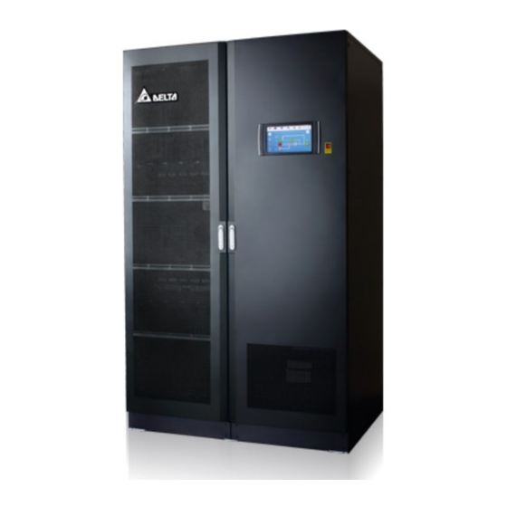
Exterior & Dimensions (Figure 2-1: 300kVA UPS_ Exterior & Dimensions) (Figure 2-2: 400/ 500/ 600kVA UPS_ Exterior & Dimensions) Ultron DPS Series... -
Page 17: Front View
Front View (Figure 2-3: Front View of 300kVA UPS) (Figure 2-4: Front View of 400/ 500/ 600kVA UPS) - Page 18 (Figure 2-5: How to Open the Front Door of 300kVA UPS) (Figure 2-6: How to Open the Front Doors of 400/ 500/ 600kVA UPS) Ultron DPS Series...
-
Page 19: Internal View
Internal View WARNING: Only authorized Delta engineers or service personnel can perform installation, wiring, panel & cover removal, maintenance and operation. If you want to execute any action mentioned above by yourself, the action must be under the supervision of authorized Delta engineers or service personnel. - Page 20 (Figure 2-8: 400/ 500/ 600 kVA UPS_ Internal View) NOTE: For 400, 500 and 600kVA UPS, their exteriors are the same. The main interior difference is the number of power cells. In this manual, only 600kVA UPS will be taken as an example for the 400/ 500/ 600kVA UPS. (Figure 2-9: 400/ 500/ 600 kVA UPS_ Interior Differences) Ultron DPS Series...
- Page 21 3. The power outlet (220/ 230/ 240Vac, 3.15A) is without galvanic isolation. NOTE: Only authorized Delta engineers or service personnel can use the power outlet. If you want to use the power outlet by yourself, it must be under the supervision of authorized Delta engineers or service personnel.
- Page 22 (Figure 2-12: 300kVA UPS_ AC Input Terminals & Bypass Input Terminals) (Figure 2-13: 300kVA UPS_ UPS Output Terminals & Battery Input Terminals) Ultron DPS Series...
- Page 23 (Figure 2-14: 300kVA UPS_ Grounding Terminals) (Figure 2-15: 400/ 500/ 600kVA UPS_ Location of the Switch Panel and Screws)
- Page 24 (Figure 2-16: 400/ 500/ 600kVA UPS_ AC Input Terminals & Bypass Input Terminals) (Figure 2-17: 400/ 500/ 600kVA UPS_ UPS Output Terminals & Battery Input Terminals) Ultron DPS Series...
-
Page 25: Tri-Color Led Indicator & Buzzer
(Figure 2-18: 400/ 500/ 600kVA UPS_ Grounding Terminals) Tri-color LED Indicator & Buzzer (Figure 2-19: Tri-color LED Indicator Location) NOTE: For information about the 10” color touch panel, please refer to 7. LCD Display & Settings. - Page 26 The buzzer is located at the rear of the front door. (Figure 2-20: 300kVA UPS_ Buzzer Location) (Figure 2-21: 400/ 500/ 600kVA UPS_ Buzzer Location) Ultron DPS Series...
- Page 27 Table 2-1: Tri-color LED Indicator, UPS Operation Mode & Buzzer Tri-color LED Status Meaning Indicator • Indicates the UPS is operating in one of the following modes: Text on the LCD Screen UPS Operation Mode (upper-right corner) Green On-Line Mode ‘On-Line’...
-
Page 28: Chapter 3 : Operation Modes
Chapter 3 : Operation Modes The UPS runs in six basic operation modes, which are On-Line mode, Battery mode, Bypass mode, Manual Bypass mode, ECO mode and Frequency Conversion mode. NOTE: 1. In this user manual, Q1, Q2, Q3, Q4 and Q5 represents the following. Code Meaning Input Switch... -
Page 29: Battery Mode
Battery Mode The UPS transfers to Battery mode automatically if the main AC source is abnormal, for example, when unstable voltage or a power outage occurs. In Battery mode, the batteries provide DC power and the UPS converts it into AC power and supplies it to the connected critical loads via the Output Switch (Q4). -
Page 30: Manual Bypass Mode
Manual Bypass Mode When the UPS works in Manual bypass mode, the current flows through the maintenance bypass instead of the power modules so that the maintenance personnel can maintain the circuit inside the UPS. However, DO NOT touch any terminal block which may carry high- voltage electricity. -
Page 31: Frequency Conversion Mode
Frequency Conversion Mode NOTE: Frequency Conversion mode is only applicable to single UPS but not to parallel UPSs. After the UPS is manually set as Frequency Conversion mode via the LCD, the inverter will automatically select 50Hz or 60Hz as the fixed output frequency. After the output frequency is determined, the system will automatically disable the bypass function. -
Page 32: Chapter 4 : Communication Interfaces
Chapter 4 : Communication Interfaces The communication interfaces are hot-swappable and located at two different places. One is on the front of the UPS with the front door open and the other is at the rear of the touch panel. See Figure 2-7 and Figure 2-8 for their positions. Communication Interfaces I: on the Front of the UPS with the Front Door Open (Figure 4-1: Communication Interfaces I) -
Page 33: Display Port
4.1.1 Display Port Before shipment, the display port has been connected to the 10” touch panel with the designated cable in Delta factory. 4.1.2 REPO Dry Contacts Connect the REPO dry contacts to a user-supplied switch and you can remotely shut down the UPS when an emergency occurs. - Page 34 (Figure 4-4: Location of the Jump CNR3) For connection to the REPO dry contacts (and other dry contacts on the communication interfaces I), please follow the instructions below to route the signal cable (user-supplied). NOTE: 1. In accordance with National Electrical Codes (NEC), please install a suitable conduit and bushing for cable protection.
- Page 35 (Figure 4-5: 300kVA UPS_ Signal Cable Routing-1) Step 2 Refer to instructions ❶ ~ ❹ below to properly route and secure the signal cable with cable ties (user-supplied). There are eight bridge lances that you can choose to use. (Figure 4-6: 300kVA UPS_ Signal Cable Routing-2)
- Page 36 400/ 500/ 600kVA UPS_ Signal Cable Routing Method (Top & Bottom Entry) Step 1 For top entry, use the snap bushing, wire mounts and M4 screws in the accessory package to install the snap bushing and fasten the wire mounts on the frame. For bottom entry, use the wire mounts and M4 screws in the accessory package to fasten the wire mounts on the frame.
- Page 37 Step 2 For top/ bottom entry, route the user-supplied signal cable (❶) through the snap bushing (❷), use a cable tie (user-supplied) for each wire mount (❸) to fix the signal cable on the frame, and connect the signal cable to the REPO dry contacts (❹). NOTE: The number of the wire mounts and cable ties shown in the figures are for reference only.
- Page 38 (Figure 4-9: 400/ 500/ 600kVA UPS_ Signal Cable Routing-2_ Bottom Entry) Ultron DPS Series...
-
Page 39: External Battery Temperature Dry Contacts
For connection to the external switch/ breaker status dry contacts, the signal cable routing is the same as the REPO dry contacts’ signal cable routing. NOTE: Only trained Delta engineers can enable the function. Please contact Delta customer service for implementation. (Figure 4-11: External Switch/ Breaker Status Dry Contacts) -
Page 40: Output Dry Contacts
4.1.5 Output Dry Contacts There are six sets of programmable output dry contacts. Please use the touch panel to set each dry contact as normally open (NO) or normally closed (NC). Each dry contact can be assigned a specific event. Six out of twenty-one events can be assigned according to your applications. - Page 41 Event Description None No set-up. Load On Inverter The UPS works in On-Line mode. Load On Bypass The UPS works in Bypass mode. When the main AC source fails, the batteries Load On Battery supply power to the critical loads. When the UPS runs in Battery mode, battery Battery Low voltage is lower than the setup limit (default:...
-
Page 42: Input Dry Contacts
Event Description When the EPO button is pressed, the UPS will Battery Breaker Shunt Trip send a signal to the connected external shunt trip device to cut off the battery power. When the UPS’s bypass SCR has a short-circuit issue, the UPS will send a signal to the Backfeed Protection connected external shunt trip device to cut off the backfeed voltage. - Page 43 (Figure 4-13: Input Dry Contacts & Schematic)
-
Page 44: Parallel Communication Cards
The battery fuse is blown. NOTE: If you use non-Delta lithium-ion batteries, you must set up Charger Off (Positive) and Charger Off (Negative) these two items. Please refer to 7.6.6 Dry Contact Setting. For settings relevant to the non-Delta lithium-ion batteries, please refer to 7.6.4 Battery &... -
Page 45: Parallel Ports
For connection to the relay I/O card’s dry contacts, the signal cable routing is the same as the REPO dry contacts’ signal cable routing. 2. If you use the Delta lithium-ion batteries, you must install the optional multifunctional communication card (MFC) into the SMART slot to monitor the battery status. For settings and information relevant to the Delta lithium-ion batteries, please refer to 7.6.4... -
Page 46: 4.1.10 Usb Port & Rs-232 Port
NOTE: One Ethernet cable is provided in each package of the optional multi-functional communication card (MFC). (Figure 4-16: Location of the SMART Slot) 4.1.10 USB Port & RS-232 Port Use an RS-232 cable (not provided) or a USB cable (provided) to connect a computer to the UPS’s RS-232 port or USB port, and you can (1) upgrade the firmware of the UPS, power modules, system control card, parallel communication cards and optional multifunctional communication card (MFC) and (2) download event logs. -
Page 47: 4.1.12 Battery Start Buttons
(Figure 4-18: Location of the Auxiliary Power Cards) 4.1.12 Battery Start Buttons For the battery start buttons’ operation information, please refer to 6.2.2 Battery Mode Start- up Procedures. (Figure 4-19: Location of the Battery Start Buttons) -
Page 48: Communication Interfaces Ii: At The Rear Of The Touch Panel
Communication Interfaces II: at the Rear of the Touch Panel (Figure 4-20: Communication Interfaces II) Ultron DPS Series... - Page 49 EMS/ CONSOLE system or Delta EnviroProbe 1000 (optional). Before shipment, the DISPLAY port has been DISPLAY connected. Connects to the Delta battery management system (optional). The BMS function is only applicable to lead- acid batteries. 1. Provides MODBUS communication service. MODBUS 2.
- Page 50 (Figure 4-21: 300kVA UPS_ Signal Cable Routing) 400/ 500/ 600kVA UPS_ Signal Cable Routing Method (Top & Bottom Entry) Step 1 For top entry, use the snap bushing, wire mounts and M4 screws in the accessory package to install the snap bushing and the wire mounts on the frame. See Figure 4-7 For bottom entry, use the wire mounts and M4 screws in the accessory package to install the wire mounts on the frame.
- Page 51 (Figure 4-22: 400/ 500/ 600kVA UPS_ Signal Cable Routing_ Top Entry)
- Page 52 (Figure 4-23: 400/ 500/ 600kVA UPS_ Bottom Entry) Ultron DPS Series...
-
Page 53: Chapter 5 : Installation And Wiring
Delta engineers or service personnel. If you use a forklift or other equipment to move the UPS, please make sure its load bearing is sufficient. Please refer to Table 5-1. - Page 54 NOTE: Dust filters have been installed on the inner side of the UPS’s front door(s) before shipment. (Figure 5-1: 300kVA UPS_ Air Inlet & Outlet Direction) Ultron DPS Series...
- Page 55 (Figure 5-2: 400/ 500/ 600kVA UPS_ Air Inlet & Outlet Direction) WARNING: 1. Do not use air conditioners or similar equipment to blow into the rear of the UPS. 2. Do not hinder ventilation of the UPS. • Keep the installation area clean. Please note that wiring routes must be hermetic to prevent possible damage from rodents.
-
Page 56: Fixing The Ups
Fixing the UPS NOTE: Please use appropriate equipment (e.g. forklift) to move the UPS. Please follow the steps below: Step 1 Before fixing the UPS in a designated installation area, please double-check whether the area’s floor weight loading is sufficient to bear the UPS, external battery cabinet(s) and handling equipment (e.g. - Page 57 (Figure 5-4: 400/ 500/ 600kVA UPS_ Location of the Stands’ Screw Holes) (Figure 5-5: 300kVA UPS_ Fix the Stands on the Ground)
- Page 58 (Figure 5-6: 400/ 500/ 600kVA UPS_ Fix the Stands on the Ground) WARNING: If you don’t fix the UPS stands on the ground, the UPS might topple over. For safety concerns, please fix the UPS stands on the ground firmly. Step 3 Follow the instructions in 5.4 Wiring to perform UPS wiring.
-
Page 59: Wiring
UPS in the designated installation area firmly. 2. Before wiring, please read 5.4 Wiring thoroughly. 3. Only authorized Delta engineers or service personnel can perform installation, wiring, panel & cover removal, maintenance and operation. If you want to execute any action mentioned above by yourself, the action must be under the supervision of authorized Delta engineers or service personnel. - Page 60 UPS Capacity 300kVA 400kVA 500kVA 600kVA Rated current at 220V 454A 606A 758A 909A 120 mm 120 mm 150 mm 185 mm Recommended cable size × 2 PCS × 3 PCS × 3 PCS × 3 PCS (L1/ L2/ L3/ N) (250 kcmil (250 kcmil (300 kcmil...
- Page 61 UPS Capacity 300kVA 400kVA 500kVA 600kVA 630A 800A 1000A 1250A Input Switch (Q1) Bypass Switch (Q2) 630A 800A 1000A 1250A Manual Bypass Switch (Q3) 630A 800A 1000A 1250A Output Switch (Q4) 630A 800A 1000A 1250A External Battery Cabinet’s Switch 1000A 1250A 1400A 1700A...
-
Page 62: Single Input To Dual Input Modification
5.4.2 Single Input to Dual Input Modification NOTE: Please keep the removed components properly for future use. If you want to modify the UPS from dual input into single input, please use the removed screws and nuts to connect the cables/ bus bars back to the AC Input terminals (L1/ L2/ L3) and the Bypass Input terminals (L1/ L2/ L3). - Page 63 (Figure 5-8: 300kVA UPS_ AC Input Terminals & Bypass Input Terminals) Step 2 Remove all the cables between the AC Input terminals (L1/ L2/ L3) and the Bypass Input terminals (L1/ L2/ L3). (Figure 5-9: 300kVA UPS_ Remove the Cables between the AC Input Terminals &...
- Page 64 ● 400/ 500/ 600kVA UPS Single Input to Dual Input Modification Step 1 Open the front door and remove the switch panel, and you will see the AC Input terminals and the Bypass Input terminals. (Figure 5-10: 400/ 500/ 600kVA UPS_ Locations of the Switch Panel and Screws) (Figure 5-11: 400/ 500/ 600kVA UPS_ AC Input Terminals &...
-
Page 65: Installation Of Insulating Plates For Top & Bottom Wiring
Step 2 Remove the six bus bars between the AC Input terminals (L1/ L2/ L3) and the Bypass Input terminals (L1/ L2/ L3). (Figure 5-12: 400/ 500/ 600kVA UPS_ Remove the Bus Bars between the AC Input Terminals & Bypass Input Terminals) 5.4.3 Installation of Insulating Plates for Top &... - Page 66 (Figure 5-13: Insulating Plates Position_ Applicable to Top Wiring (Factory Default)) Step 2 Remove the four plastic rivets on each of the insulating plates. Turn the insulating plates 180° and install them back to the original positions. NOTE: 1. If the plastic rivets are damaged, please use spares in the accessory package for replacement.
-
Page 67: Single Unit Wiring
(Figure 5-15: Insulating Plates Position_ Applicable to Bottom Wiring) 5.4.4 Single Unit Wiring NOTE: Before wiring, please read 5.4 Wiring thoroughly and make sure relevant conditions have been met. Refer to Table 5-3 for information of the wiring terminals. For the wiring diagrams and instructions, please refer to the following sections. - Page 68 Item Description Function One grounding For the UPS’s protective earthing. terminal Connect to the external battery cabinet’s Two grounding grounding ( ) and the critical load’s terminals grounding ( ). 5.4.4.1 300kVA UPS Single Input (Single Unit) When there is only one AC power source, single unit wiring procedures are as follows. Step 1 The 300kVA UPS only allows cable routing from the top.
- Page 69 Step 4 Make sure that the Input Switch (Q1), Bypass Switch (Q2), Manual Bypass Switch (Q3), and Output Switch (Q4) are in the OFF position. Step 5 Make sure each external battery cabinet’s breaker (Q5) is in the OFF position. Step 6 Follow Table 5-2 to select proper input, output, and battery cables.
- Page 70 Single Input_ Top Wiring_ Step 2 (Figure 5-18: 300kVA UPS Single Unit Single Input_ Top Wiring_ Step 2) Single Input_ Top Wiring_ Step 3 (Figure 5-19: Single Unit Single Input_ Top Wiring_ Step 3) Ultron DPS Series...
- Page 71 Step 8 Follow the figure below to ground the UPS, external battery cabinet(s) and connected critical loads. (Figure 5-20: Grounding Diagram_ Single Unit) 5.4.4.2 300kVA UPS Dual Input (Single Unit) When there are two AC power sources, single unit wiring procedures are as follows. Step 1 Follow 5.4.2 Single Input/ Dual Input Modification to modify the UPS from single input to dual input.
- Page 72 (Figure 5-21: Single Unit Dual Input_ Top Wiring _ Step 1) Dual Input_ Top Wiring_ Step 2 (Figure 5-22: Single Unit Dual Input_ Top Wiring_ Step 2) Ultron DPS Series...
- Page 73 Dual Input_ Top Wiring_ Step 3 (Figure 5-23: Single Unit Dual Input_ Top Wiring_ Step 3) Step 4 Follow Figure 5-20 to ground the UPS, external battery cabinet(s) and connected critical loads. 5.4.4.3 400/ 500/ 600kVA UPS Single Input (Single Unit) When there is only one AC power source, single unit wiring procedures are as follows.
- Page 74 (Figure 5-24: Location of the 400/ 500/ 600kVA UPS’s Top Covers) Step 4 For bottom wiring, please remove the bottom cover. (Figure 5-25: Location of the 400/ 500/ 600kVA UPS’s Bottom Cover) Ultron DPS Series...
- Page 75 Step 5 Make sure that the Input Switch (Q1), Bypass Switch (Q2), Manual Bypass Switch (Q3), and Output Switch (Q4) are in the OFF position. Step 6 Make sure each external battery cabinet’s breaker (Q5) is in the OFF position. Step 7 Follow Table 5-2 to select proper input, output, and battery cables.
- Page 76 Single Input_ Top Wiring_ Step 2 (Figure 5-27: 400/ 500/ 600kVA UPS Single Unit Single Input_ Top Wiring_ Step 2) Single Input_ Top Wiring_ Step 3 (Figure 5-28: 400/ 500/ 600kVA UPS Single Unit Single Input_ Top Wiring _ Step 3) Ultron DPS Series...
- Page 77 Single Input_ Bottom Wiring_ Step 1 (Figure 5-29: 400/ 500/ 600kVA UPS Single Unit Single Input_ Bottom Wiring _ Step 1) Single Input_ Bottom Wiring_ Step 2 (Figure 5-30: 400/ 500/ 600kVA UPS Single Unit Single Input_ Bottom Wiring _ Step 2)
- Page 78 Single Input_ Bottom Wiring_ Step 3 (Figure 5-31: 400/ 500/ 600kVA UPS Single Unit Single Input_ Bottom Wiring_ Step 3) Step 9 Follow Figure 5-20 to ground the UPS, external battery cabinet(s) and connected critical loads. 5.4.4.4 400/ 500/ 600kVA UPS Dual Input (Single Unit) When there are two AC power sources, single unit wiring procedures are as follows.
- Page 79 Dual Input_ Top Wiring_ Step 1 (Figure 5-32: 400/ 500/ 600kVA UPS Single Unit Dual Input_ Top Wiring_ Step 1) Dual Input_ Top Wiring_ Step 2 (Figure 5-33: 400/ 500/ 600kVA UPS Single Unit Dual Input_ Top Wiring _ Step 2)
- Page 80 Dual Input_ Top Wiring_ Step 3 (Figure 5-34: 400/ 500/ 600kVA UPS Single Unit Dual Input_ Top Wiring _ Step 3) Dual Input_ Bottom Wiring_ Step 1 (Figure 5-35: 400/ 500/ 600kVA UPS Single Unit Dual Input_ Bottom Wiring_ Step 1) Ultron DPS Series...
- Page 81 Dual Input_ Bottom Wiring_ Step 2 (Figure 5-36: 400/ 500/ 600kVA UPS Single Unit Dual Input_ Bottom Wiring_ Step 2) Dual Input_ Bottom Wiring_ Step 3 (Figure 5-37: 400/ 500/ 600kVA UPS Single Unit Dual Input_ Bottom Wiring_ Step 3)
-
Page 82: Parallel Units Wiring
Step 4 Follow Figure 5-20 to ground the UPS, external battery cabinet(s) and connected critical loads. 5.4.5 Parallel Units Wiring NOTE: 1. Up to eight UPS units can be paralleled for redundancy and capacity expansion. Only the UPSs with the same capacity, voltage, frequency and version can be paralleled. - Page 83 (Figure 5-38: Parallel Units Single Input Wiring Diagram) Step 3 Use the provided parallel cables* to connect the parallel ports of the parallel units. Please adopt Daisy Chain method. For the parallel port location, refer to Figure 4-1. NOTE: One parallel cable is provided in each UPS’s accessory package. (Figure 5-39: Parallel Port Connection_ Daisy Chain Method)
- Page 84 Follow the instructions below to route the provided parallel cables. NOTE: 1. In accordance with National Electrical Codes (NEC), please install a suitable conduit and bushing for cable protection. 2. If you adopt top entry, please remove the knockout cover(s) at the top of the UPS before performing the steps below.
- Page 85 (Figure 5-41: 300kVA UPS_ Parallel Cable Routing-2) 400/ 500/ 600kVA UPS_ Parallel Cable Routing Method (Top & Bottom Entry) (Step A) For top entry, use the snap bushing, wire mounts and M4 screws in the accessory package to install the snap bushing and fasten the wire mounts on the frame. For bottom entry, use the wire mounts and M4 screws in the accessory package to install the wire mounts on the frame.
- Page 86 (Step B) For top/ bottom entry, route the provided parallel cables ( ❶ ) through the snap bushing ( ❷ ), use a cable tie (user-supplied) for each wire mount to fix the parallel cables on the frame ( ❸ ), and connect the parallel cables to the parallel ports ( ❹ ). NOTE: The number of the wire mounts and cable ties shown in the figures are for reference only.
- Page 87 (Figure 5-44: 400/ 500/ 600kVA UPS_ Parallel Cable Routing-2_ Bottom Entry)
- Page 88 Step 4 Follow the figure below to ground the parallel UPS units, external battery cabinet(s) and connected critical loads. (Figure 5-45: Grounding Diagram_ Parallel Units) WARNING: Before start-up of the parallel units, qualified service personnel must set each UPS’s 'Parallel Group ID' (1 or 2) and 'Parallel ID' (1 ~ 8) through the LCD. Otherwise, the parallel UPSs cannot be started.
-
Page 89: External Battery Cabinet Connection Warnings
For relevant information, please refer to the manual of the lithium-ion batteries. Whether you use the lead-acid batteries or the lithium-ion batteries, please contact Delta service personnel for any battery/ battery cabinet’s setup and configurations. You should connect the UPS with at least one external battery cabinet to ensure that the connected critical loads are protected when a power failure occurs. - Page 90 • According to on-site requirements, you can choose 12V × 30/ 32/ 34/ 36/ 38/ 40/ 42/ 44 or 46 PCS of batteries. Change of the battery quantity will influence the applied specifications. For battery selection, installation and replacement, please contact your local dealer or customer service.
- Page 91 NOTE: 1. Table 5-4 is for 12Vdc × 40 PCS of the batteries (default). If you install a different number of batteries, please contact Delta service personnel for protective device’s current and voltage values. 2. If you need to parallel multiple units of external battery cabinets, please contact Delta service personnel for relevant information.
- Page 92 • The protective device is optional, and its type must be fast-acting DC circuit breaker and/ or fast-acting DC fuse. If you want to buy any of them, please contact Delta service personnel. When choosing the protective device, follow the instructions below.
- Page 93 External Battery Cabinet’s Protective Device (Option 2) (Figure 5-49: Installation of a 3-pole DC Isolated Switch in Series with DC Fuses) External Battery Cabinet’s Protective Device (Option 3) (Figure 5-50: Installation of a 4-pole DC Circuit Breaker in Series with Optional DC Fuses)
- Page 94 For relevant information, please refer to the user manual of the lithium-ion batteries. Whether you use the lead-acid batteries or the lithium-ion batteries, please contact Delta service personnel for any battery/ battery cabinet’s setup and configurations. For common battery application, please install a protective device between each parallel UPS and its connected external battery cabinet(s).
- Page 95 (Figure 5-52: Common Battery Diagram) WARNING: 1. Before performing battery/ battery cabinet replacement, please turn off each external battery cabinet’s breaker (Q5) to completely disconnect the battery power from the UPS. 2. A battery can present a risk of electric shock and high short-circuit current. Servicing of batteries and battery cabinets must be performed or supervised by qualified service personnel knowledgeable in batteries, battery cabinets and the required precautions.
- Page 96 ● External Battery Cabinet Alarm When any external battery cabinet connected to the UPS has the following problems, the UPS system will sound an alarm. Please see the table below. External Battery Cabinet Status Alarm Battery Abnormal - Reversed Sounds for 0.5 second every second. Battery Ground Fault Sounds for 0.5 second every second.
-
Page 97: Installation Of Rodent Shields
Installation of Rodent Shields To prevent potential hazards posed by rodents, please install the rodent shields (provided) at the bottom of the UPS. 5.6.1 Installation of 300kVA UPS’s Rodent Shields Table 5-5: 300kVA UPS_ Rodent Shield Quantity Rodent Shield Type 1 PC 1 PC 2 PCS... - Page 98 Step 2 Install the rodent shield B to the rear bottom of the UPS. (Figure 5-54: 300kVA UPS_ Install the Rodent Shield B) Step 3 Install the rodent shields C to the bottom of the two sides. (Figure 5-55: 300kVA UPS_ Install the Rodent Shields C) Ultron DPS Series...
-
Page 99: Installation Of 400/ 500/ 600Kva Ups's Rodent Shields
5.6.2 Installation of 400/ 500/ 600kVA UPS’s Rodent Shields Table 5-6: 400/ 500/ 600kVA UPS_ Rodent Shield Quantity Rodent Shield Type Quantity 1 PC 1 PC 1 PC 1 PC 2 PCS Step 1 Install the rodent shields A and B to the front bottom of the UPS. (Figure 5-56: 400/ 500/ 600 kVA UPS_ Install the Rodent Shields A &... - Page 100 Step 3 Install the rodent shields E to the bottom of the two sides. (Figure 5-58: 400/ 500/ 600 kVA UPS_ Install the Rodent Shields E) Ultron DPS Series...
-
Page 101: Chapter 6 : Ups Operation
4. The external battery cabinet’s breaker (Q5) shown on the LCD is always ON by default. To enable the detection of the Q5 status via the LCD, please contact Delta customer service for additional configurations. • Pre Start-up Warnings 1. Before UPS operation, ensure that installation and wiring have been completely done according to 5. -
Page 102: Start-Up Procedures
Pre Turn-off Warnings • 1. Before you perform the turn-off procedures, please make sure the critical loads connected to the UPS have already been safely shut down. 2. Please follow the turn-off procedures for each of the operation modes to shut down the UPS and make sure the Output Switch (Q4) is the last one to be turned off. -
Page 103: Battery Mode Start-Up Procedures
6.2.2 Battery Mode Start-up Procedures WARNING: Before turning on the UPS, please read 6.1 Pre Start-up & Pre Turn-off Warnings thoroughly and ensure that the precautions and instructions have been followed. Step 1 Ensure that the Manual Bypass Switch (Q3) is in the OFF position. Step 2 Switch ON every external battery cabinet’s breaker (Q5). -
Page 104: Bypass Mode Start-Up Procedures
6.2.3 Bypass Mode Start-up Procedures WARNING: Before turning on the UPS, please read 6.1 Pre Start-up & Pre Turn-off Warnings thoroughly and ensure that the precautions and instructions have been followed. Step 1 Ensure that the Manual Bypass Switch (Q3) is in the OFF position. Step 2 Switch ON the Output Switch (Q4). -
Page 105: Manual Bypass Mode Start-Up Procedures
1. Before turning on/ off the UPS, please read 6.1 Pre Start-up & Pre Turn-off Warnings thoroughly and ensure that the precautions and instructions have been followed. 2. To enable Manual Bypass mode, please contact Delta customer service for operation. 3. In Manual Bypass Mode, make sure that all of the switches/ breakers (except for the Manual Bypass Switch (Q3)) are in the OFF position before working on the UPS’s internal circuit to prevent electric shock. - Page 106 From Manual Bypass Mode to On-Line Mode • Step 1 Switch ON every external battery cabinet’s breaker (Q5). Step 2 Switch ON the Output Switch (Q4). Step 3 Switch ON the Input Switch (Q1) and Bypass Switch (Q2). Step 4 Switch OFF the Manual Bypass Switch (Q3).
-
Page 107: Eco Mode Start-Up Procedures
6.2.5 ECO Mode Start-up Procedures WARNING: Before turning on the UPS, please read 6.1 Pre Start-up & Pre Turn-off Warnings thoroughly and ensure that the precautions and instructions have been followed. Step 1 Ensure that the Manual Bypass Switch (Q3) is in the OFF position. Step 2 Switch ON every external battery cabinet’s breaker (Q5). - Page 108 Step 6 Go to SETUP → Mode Setting → Select ECO. Step 7 Tap the icon ( ) to go back to the Main Screen and tap the ON/ OFF Button ( Step 8 After the inverter turns on and the system confirms that the bypass voltage is normal, the UPS will automatically transfer to ECO mode to let the bypass supply power, the LCD screen will show as below, and the tri-color LED indicator will illuminate green.
-
Page 109: Frequency Conversion Mode Start-Up Procedures
6.2.6 Frequency Conversion Mode Start-up Procedures WARNING: 1. Before turning on the UPS, please read 6.1 Pre Start-up & Pre Turn-off Warnings thoroughly and ensure that the precautions and instructions have been followed. 2. Frequency Conversion mode is only applicable to single UPS but not to parallel UPSs. - Page 110 Step 6 Go to SETUP → Mode Setting → Select Frequency Conversion. WARNING: Once you select 'Frequency Conversion' mode, the UPS will run in Standby mode and the output will be terminated. Step 7 Tap the icon ( ) to go back to the Main Screen and tap the ON/ OFF Button ( Step 8 After the inverter turns on, the UPS will run in Frequency Conversion mode, the output frequency will be the same as the setup value, the LCD screen will show as below, and the tri-...
-
Page 111: Turn-Off Procedures
Turn-off Procedures 6.3.1 On-Line Mode Turn-off Procedures WARNING: Before turning off the UPS, please read 6.1 Pre Start-up & Pre Turn-off Warnings thoroughly and ensure that the precautions and instructions have been followed. Step 1 Tap the ON/ OFF Button ( ) to shut down the UPS’s inverter. -
Page 112: Bypass Mode Turn-Off Procedures
6.3.3 Bypass Mode Turn-off Procedures WARNING: Before turning off the UPS, please read 6.1 Pre Start-up & Pre Turn-off Warnings thoroughly and ensure that the precautions and instructions have been followed. Step 1 Switch OFF the Input Switch (Q1) and Bypass Switch (Q2), and the UPS will transfer to Standby mode. -
Page 113: Frequency Conversion Mode Turn-Off Procedures
6.3.6 Frequency Conversion Mode Turn-off Procedures WARNING: Before turning off the UPS, please read 6.1 Pre Start-up & Pre Turn-off Warnings thoroughly and ensure that the precautions and instructions have been followed. Step 1 Tap the ON/ OFF Button ( ) to shut down the UPS’s inverter. - Page 114 Ensure that the output voltage difference between each parallel UPS is below 3V. Only authorized Delta engineers or service personnel can check the output voltage difference, or it must be done under the supervision of authorized Delta engineers or service personnel. Step 5 Now, the UPSs are ready to operate in parallel.
-
Page 115: Chapter 7 : Lcd Display & Settings
Chapter 7 : LCD Display & Settings LCD Display Hierarchy Please refer to Figure 7-1 for an overview of all the LCD items. For some of the items marked with an asterisk, they will show up only under certain conditions. Please refer to the note below for details. - Page 116 Ultron DPS Series...
- Page 117 (Figure 7-1: LCD Display Hierarchy)
-
Page 118: How To Turn On The Lcd
To display the item(s), you have to log in as Administrator. Please refer to 7.4 Password Entry. The item(s) will show up only when you use the Delta lithium-ion batteries and have installed the optional multifunctional communication card (MFC) in the SMART slot. -
Page 119: Introduction Of Touch Panel And Function Keys
Introduction of Touch Panel and Function Keys... - Page 120 Text/ Button Symbol Digital Function Display Icon/ Text Display Description (Yes or (Yes or (Yes or Tap the button to go back to the Main Screen. The figure ( ) below the icon ) indicates the parallel group ID no. (the former one) and the parallel ID no.
- Page 121 Text/ Button Symbol Digital Function Display Icon/ Text Display Description (Yes or (Yes or (Yes or 1. Historical event screen shortcut button ( 2. When the icon is blue ( ), it means there is no warning event. 1.
- Page 122 Text/ Button Symbol Digital Function Display Icon/ Text Display Description (Yes or (Yes or (Yes or Tap the button to check the system status, including auxiliary power card status, system control card status and parallel communication card status. Tap the button to check the EMS status. To enable the function, you have to connect an optional EMS 1000 ...
- Page 123 Text/ Button Symbol Digital Function Display Icon/ Text Display Description (Yes or (Yes or (Yes or Indicates bypass static switch status (Green: ON/ Gray: Abnormal or OFF). Indicates rectifier status (Green: Normal/ Gray: Waiting or OFF). 1. Indicates inverter status (Green: Normal/ Gray: Waiting or OFF).
- Page 124 Icon Function Increase. Decrease. 1. Indicates the page no. 2. Choose to go to a specific page no. Delete. Capital. Space. NOTE: 1. After the backlight is turned off, you can tap the LCD to return to the Main Screen. 2.
-
Page 125: Password Entry
Password Entry 1. Administrator login requires a password while User login does not. 2. Tap → enter the Administrator password (contact service personnel for the default password) → the icon appears, indicating the Administrator login is successful. 3. To change the Administrator password, please go to →... - Page 126 Item Description Sheet Tabs Tap the sheet tabs to view the kWh statistics and (Day/ Week/ Month/ column charts of different time scales. Year/ Since Reset) 1. Shows the UPS’s main input kWh statistics, with time on X-axis and kWh on Y-axis. Column Chart 2.
-
Page 127: Ups Settings
UPS Settings This chapter lists all the UPS setting items for your reference (not including the setting items for the optional accessories). Some items will show up only under certain conditions. Please refer to 7.1 LCD Display Hierarchy for details. 7.6.1 Bypass Setting Path:... -
Page 128: Output Setting
7.6.3 Output Setting Path: → Output Setting Item Description Voltage Set up the output voltage. When the UPS is distant from the loads and there is a voltage drop Voltage in the output, you can adjust the INV output voltage amplitude for Compensation voltage compensation. -
Page 129: Battery & Charging Setting
If you use the Delta lithium-ion batteries, please set up the battery type as 'LiB (Integration)'. The item 'LiB (Integration)' will only appear on the LCD if you use the Delta lithium-ion batteries with the optional multifunctional communication card (MFC) being installed in the SMART slot. Please contact Delta customer service if you need more information. - Page 130 Item Description Set up the restored voltage. NOTE: 1. The item will only show up if the Battery Type is Restored Voltage set as 'LiB (Integration)'. 2. If the Battery Type is set as 'LiB (Dry Contact)', the item will not show up. Charge Current (Max) Set up the maximum charge current.
-
Page 131: Parallel Setting
7.6.5 Parallel Setting Path: → Parallel Setting Item Description The UPSs in parallel connection must be assigned the same parallel group ID no. in order to let the outputs of the parallel UPSs be put in parallel Parallel connection and let the loads be evenly distributed among the parallel units. Group ID If the parallel UPSs have different parallel group ID no., their output signals might be synchronized but their outputs cannot be connected in parallel. - Page 132 Output Dry Event Selection Type Contact No. 1. None 2. Load On Inverter 3. Load On Bypass 4. Load On Battery 5. Battery Low 6. Battery Input Abnormal 7. Battery Test Fail 8. Internal Comm. Fail Output Dry Contact 1 9.
-
Page 133: General Setting
7.6.7 General Setting Path: → General Setting Item Sub Item Description Date Format Select the date format. DATE/ Date Set up the date. TIME Time Set up the time. Screen Brightness Adjust the LCD display brightness (default: 80). SCREEN Set up the LCD backlight sleep time (default: 1 Screen Sleep (after) minute). -
Page 134: Ip Setting
7.6.8 IP Setting Path: → IP Setting Item Description DHCP Client Enable or disable the DHCP client. IP Address Set up the IP address. Subnet Mask Set up the subnet mask. Set up the gateway IP address. Gateway IP Set up the DNS server 1 IP address. DNS 1 IP Set up the DNS server 2 IP address. -
Page 135: System Maintenance
System Maintenance 7.7.1 Warning Path 1: → Warning Path 2: When there is a warning, the buzzer icon ( ) will light up in red, and the buzzer will sound. Tap the warning icon ( ) to enter the WARNING screen. The system can store a maximum of 200 warning logs. -
Page 136: Statistics
7.7.3 Statistics Path: → Statistics Item Description In Battery Mode Shows how long and how many times the UPS runs in Battery mode. In Bypass Mode Shows how long and how many times the UPS runs in Bypass mode. Operation Time Means how long the UPS has operated. To clear the statistics, please refer to 7.7.5 Clear. -
Page 137: Advanced Diagnosis
7.7.6 Advanced Diagnosis Path: → Advanced Diagnosis This is an optional function. If you would like to access this page, please contact Delta customer service. 7.7.7 Version & S/N NOTE: To operate the UPSs in parallel, please make sure all the versions below are the same between each parallel unit. -
Page 138: Chapter 8 : Optional Accessories
Screen and 7.6.4 Battery & Charging Setting. System (BMS) NOTE: The quantity of BMS to be installed depends on how many external battery cabinets (lead-acid batteries) are connected to the UPS. For BMS installation, please contact Delta customer service. Ultron DPS Series... - Page 139 Item Function If you use the Delta lithium-ion batteries, you must purchase and install the multifunctional communication card (MFC) in the SMART slot shown in Figure 4-1 to monitor the battery status via the UPS’s LCD. For relevant information, please Multifunctional refer to 8.3 MFC Function on the LCD Screen.
-
Page 140: Ems Function On The Lcd Screen
EMS Function on the LCD Screen Path 1: Tap the shortcut button ( ) on the Main Screen. Path 2: → EMS To activate the EMS function, you have to connect the optional EMS 1000 (EnviroProbe) device with the UPS and perform the EMS settings via the LCD. After that, the EMS information of each device (ID #) will be displayed on the EMS screen. - Page 141 Color Item Descriptions (Status) The color represents the status of Temperature/ Humidity based on the EMS settings. Green (Normal) When the detected Temperature/ Humidity Tempera- Yellow (Warning) 1. is lower than the value set for Warning, it ture Red (Alarm) shows Green (Normal).
- Page 142 4. To enable the EMS function, you have to set up relevant items on the LCD after connecting the optional EMS 1000 (EnviroProbe) to the UPS. → EMS Setting (Administrator login required) Path: NOTE: The default values are shown in the figures above. Ultron DPS Series...
- Page 143 Item Sub Item Description Set the ID # (ID 0/ ID 1/ …/ ID 15) according to the ID DIP switch setting of the EMS 1000 (EnviroProbe) device. NOTE: If the ID # setting is wrong, the warning message 'The EMS 1000 ID # Communication Fail' will appear.
-
Page 144: Bms Function On The Lcd Screen
Cell Voltage, String Voltage and Ambient Temperature* & Low)* You can also set up the following items. These settings must be carried out by qualified service personnel. Please contact Delta customer service for assistance. NOTE: 1. * The Alarm Threshold Values (High & Low) are defined by the service personnel during the installation process of the optional battery management system (BMS). - Page 145 Item Description Module Select Main/ Ext #n module. Module Address Set the module address. Module Type Set the module type as Voltage Type/ Internal Resistance. The status ‘Enable/ Disable’ determines whether or not the LCD Status shows the BMS information of the optional battery management system (BMS).
-
Page 146: Mfc Function On The Lcd Screen
The PAGE 3 & MFC screens (see the figures below) will only appear on the LCD if you use the Delta lithium-ion batteries with the optional multifunctional communication (MFC) card being installed in the SMART slot. Please contact Delta customer service if you need more information. - Page 147 Item Sub Item Description Set up the MODBUS ID for the optional MODBUS ID multifunctional communication card (MFC). (Multifunctional Communication MODBUS Baud Set up the MODBUS baud rate for the optional Card) Rate multifunctional communication card (MFC). Path: → Version & S/N Item Sub Item Description...
- Page 148 Chapter 9 : Maintenance • 1. UPS Cleaning: Regularly clean the UPS, especially the slits, openings and filters, to ensure that the air freely flows into the UPS to avoid overheating. If necessary, use an air blower to clean the slits and openings and replace the filters regularly to prevent any object from blocking or covering these areas.
- Page 149 Appendix 1 : Technical Specifications Model 300kVA/ 400kVA/ 500kVA/ 600kVA/ UPS Capacity 300kW 400kW 500kW 600kW 220/380 Vac, 230/400 Vac, 240/415 Vac Nominal Voltage (3Φ4W + G) Voltage Range 176 ~ 276 Vac* (full load) Input Current Harmonic ≤ 3%* Distortion Power Factor >...
- Page 150 Model 300kVA/ 400kVA/ 500kVA/ 600kVA/ UPS Capacity 300kW 400kW 500kW 600kW Protection of Battery Deep Discharge 1000 meters (without derating) Operating Altitude 3280 ft (without derating) Operating 0 ~ 40°C (32 ~ 104°F) Temperature Relative Humidity 95% (non-condensing) Environment < 80 dBA* Audible Noise 1 meter (3.28 ft) in front of the UPS IP Degree of...
- Page 151 NOTE: 1. * : With a load capacity of 70%, the input voltage range will be 132/228 ~ 276/478 Vac. 2. * : When input vTHD is < 1%. 3. * : When the environment temperature is below 30°C (86°F). 4.
- Page 152 Appendix 2 : Warranty Seller warrants this product, if used in accordance with all applicable instructions, to be free from original defects in material and workmanship within the warranty period. If the product has any failure problem within the warranty period, Seller will repair or replace the product at its sole discretion according to the failure situation.
- Page 153 - Regional Office The United States Australia Delta Electronics (Americas) Ltd. Delta Energy Systems Australia Pty Ltd. 46101 Fremont Blvd. Fremont, CA 94538 Unit 20-21, 45 Normanby Road, Notting Hill VIC 3168, Australia T +1 510 344 2157 T +61 3 9543 3720 E ups.na@deltaww.com...
Need help?
Do you have a question about the Ultron Series and is the answer not in the manual?
Questions and answers