
Related Manuals for Delta DPS-400K


Summary of Contents for Delta DPS-400K
- Page 1 The power behind competitiveness Delta UPS - Ultron Family DPS Series, Three Phase 300/ 400/ 500 kVA User Manual www.deltapowersolutions.com...
- Page 2 Manual at any time without obligation to notify any person of such revision or changes. Delta will make all possible efforts to secure the accuracy and the integrity of this Manual. Delta disclaims any kinds or forms of warranty, guarantee, or undertaking, either expressly or implicitly, including but not limited to the completeness, Manual.
-
Page 3: Table Of Contents
Table of Contents Table of Contents Important Safety Instructions ---------------------------------------------- 1-1 Installation Warnings ---------------------------------------------------------------------- 1-2 Connection Warnings --------------------------------------------------------------------- 1-2 Usage Warnings --------------------------------------------------------------------------- 1-3 Storage Warnings ------------------------------------------------------------------------- 1-4 Glossary of Symbols ---------------------------------------------------------------------- 1-5 Standard Compliance -------------------------------------------------------------------- 1-6 Introduction ---------------------------------------------------------------------- 2-1 General Overview ------------------------------------------------------------------------- 2-2 Package Inspection ----------------------------------------------------------------------- 2-2 Functions &... - Page 4 Bypass Mode (Single) ------------------------------------------------------------------- 3-4 Manual Bypass Mode (Single) -------------------------------------------------------- 3-5 ECO Mode ---------------------------------------------------------------------------------- 3-6 Normal Mode (Parallel) ------------------------------------------------------------------ 3-7 Battery Mode (Parallel) ------------------------------------------------------------------ 3-8 Bypass Mode (Parallel) ----------------------------------------------------------------- 3-9 Manual Bypass Mode (Parallel) ------------------------------------------------------3-10 3.10 Common Battery -------------------------------------------------------------------------- 3-11 Communication Interfaces -------------------------------------------------- 4-1 Smart Slots ---------------------------------------------------------------------------------- 4-2 RS-232 Port &...
- Page 5 Table of Contents Package Inspection ---------------------------------------------------------------------- 6-3 Installation ----------------------------------------------------------------------------------- 6-4 Wiring ----------------------------------------------------------------------------------------- 6-9 UPS Operation------------------------------------------------------------------- 7-1 Single Unit Operation Procedures ----------------------------------------------------- 7-2 7.1.1 Normal Mode Start-up Procedures (Single) ------------------------------ 7-2 7.1.2 Battery Mode Start-up Procedures (Single) ------------------------------ 7-4 7.1.3 Bypass Mode Start-up Procedures (Single) ----------------------------- 7-6 7.1.4 Manual Bypass Mode Start-up Procedures (Single Unit) ------------- 7-7 7.1.5...
- Page 6 8.7.1 Bypass setup --------------------------------------------------------------------8-10 8.7.2 Output Setup --------------------------------------------------------------------8-10 8.7.3 Battery Setup -------------------------------------------------------------------- 8-11 8.7.4 Charger Setup ------------------------------------------------------------------8-12 8.7.5 Parallel Setup -------------------------------------------------------------------8-13 8.7.6 Test, Buzzer and LED Setup, and Module Reset ----------------------8-14 8.7.7 Local Setup ----------------------------------------------------------------------8-15 8.7.8 Dust Filter Setup ---------------------------------------------------------------8-16 System Maintenance --------------------------------------------------------------------8-17 8.8.1 Check/ Clear Event Log ------------------------------------------------------8-17...
-
Page 7: Important Safety Instructions
Important Safety Instructions Important Safety Instructions 1.1 Installation Warnings 1.2 Connection Warnings 1.3 Usage Warnings 1.4 Storage Warnings 1.5 Glossary of Symbols 1.6 Standard Compliance... -
Page 8: Installation Warnings
Leave adequate space around all sides of the UPS for proper ventilation and mainte- nance. Please refer to 5.2 Installation Environment. Only authorized Delta engineers or service personnel can perform installation and maintenance. If you want to install the UPS by yourself, please install it under the su- pervision of authorized Delta engineers or service personnel Follow the IEC 60364-4-42 standard to install the UPS. -
Page 9: Usage Warnings
The UPS can be used to power computers and associated peripheral devices, such as monitors, modems, cartridge tape drives, external hard drives, etc. If you want to con- nect inductive or capacitive loads to the UPS, it needs derating. Please contact Delta service personnel for derating information. -
Page 10: Storage Warnings
4. Do not lay tools or metal parts on the top of batteries. 5. Disconnect the charging source prior to connecting or disconnecting the batteries’ terminals. You must contact Delta customer service department if either of the following events oc- cur: 1. Liquid is poured or splashed on the UPS. -
Page 11: Glossary Of Symbols
Important Safety Instructions Glossary of Symbols Symbol Description R-phase S-phase T-phase Neutral Grounding (Protective earthing conductor) Bonded to ground Positive battery terminal Negative battery terminal ON button OFF button EPO button E P O Main AC source LED Bypass AC source LED Inverter Start-up LED Inverter Power Supply LED Bypass Power Supply LED... -
Page 12: Standard Compliance
Symbol Description Input Switch/ Bypass Switch/ Manual Bypass Switch/ Output Switch is in the OFF position. Static Switch is in the OFF position. Input Switch/ Bypass Switch/ Manual Bypass Switch/ Output Switch/ Static Switch is in the ON position. Parallel cable is abnormal. Parallel cable connected. -
Page 13: Introduction
Introduction Introduction 2.1 General Overview 2.2 Package Inspection 2.3 Functions & Features 2.4 Exterior 2.5 Control Panel 2.6 Internal Mechanisms 2.7 Fans... -
Page 14: General Overview
General Overview The DPS series UPS, a three-phase four-wire on-line uninterruptible power supply, is a dedicated design for large scale power systems such as data centers, communication systems, network rooms, emergency systems and factory facilities. The unit adopts advanced IGBT technology to provide perfect, clean, pure sine waves and high-quality low noise, and high reliability. -
Page 15: Functions & Features
Introduction Item Quantity UPS (Without Top Cable Entry Cabinet) 1 pc User Manual 1 pc Software CD-UPSentry 2012 1 pc 1 pc (two copies placed inside the UPS cabinet) USB Cable 1 pc RS-232 Cable 1 pc (1.8-meter long) Parallel Cable 1 pc (5-meter long) Rodent Shield A 2 pcs... - Page 16 Automatic input frequency detection enables operation at 50Hz or 60Hz. Optional ECO Mode: when input voltage and frequency are within the range of rating voltage ±10% and rating frequency ±5Hz, the UPS will transfer to bypass mode; other- Automatically detects whether bypass voltage is out of rating voltage. If yes, the UPS will stop supplying power to the critical loads to protect your electronic equipment.
-
Page 17: Exterior
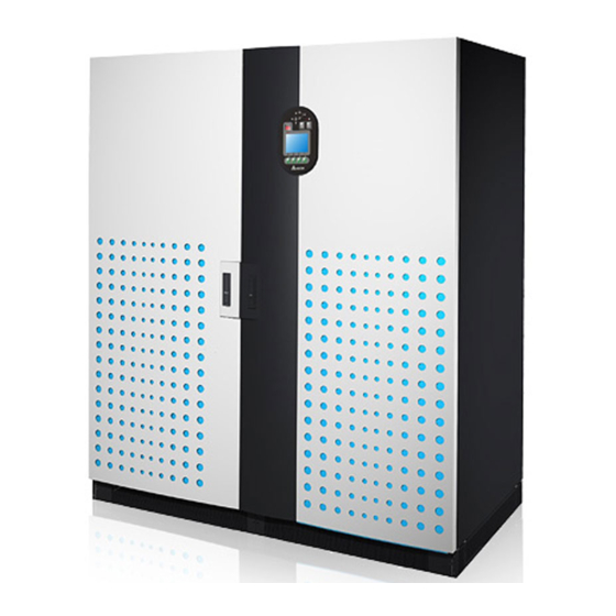
Introduction Exterior On the front of the UPS, there is a control panel and two lockable door switches. On the top, there are fans to ventilate the UPS to prevent overheating. Fans Control Panel Lockable Door Switches Foot (Figure 2-1: UPS Exterior) 2.4.1 Dimensions 1950 1 6 0... -
Page 18: Other Views
2.4.2 Other Views Open Door: there are two door handles and one control panel on the front of the cabi- net. To open the front doors, please refer to Figure 2-3. Front View with Door Open: after opening the doors, you can see internal mecha- nisms. -
Page 19: Control Panel
Introduction Control Panel 2.5.1 LED Indicators 2.5.2 ON, OFF, and EPO Buttons 2.5.3 LCD Display 2.5.4 Function Keys (Figure 2-5: UPS Control Panel) 2.5.1 LED Indicators Fault (Figure 2-6: LED Indicators) No. LED Symbol Indicates LED On Meaning Bypass AC Green When bypass AC Source is normal. -
Page 20: On, Off, And Epo Buttons
No. LED Symbol Indicates LED On Meaning When you turn on the Output Output Switch Green Switch (Q4). Inverter Power When the inverter supplies power Green Supply to the critical loads. Fault When problems occur. 2.5.2 ON, OFF, and EPO Buttons Button Name Function... -
Page 21: Function Keys
Introduction 2.5.4 Function Keys There are no symbols on the function keys. The functions of keys depend on symbols ap- pearing on the LCD. Please see the table below. Symbol Function Goes back to previous screen or cancels current selection. Moves up. -
Page 22: Auxiliary Power Fuse And Ac Outlet Fuse
Turn on a switch: (ON) (OFF) ON I ON I P.S. AC OUTLET FUSE FUSE ON I ON I ON I ON I INPUT SWITCH BYPASS SWITCH MANUAL BYPASS SWITCH OUTPUT SWITCH AC OUTLET 220/230/240Vac,8A 90° Turn off a switch: (ON) (OFF) 240VDC... -
Page 23: Wiring Terminal Block
Introduction Open a fuse holder: Close a fuse holder: 90° 90° Auxiliary Power Fuse AC Outlet Auxiliary Power AC Outlet Holder Fuse Holder Fuse Holder Fuse Holder P.S. AC OUTLET FUSE FUSE ON I ON I ON I ON I INPUT SWITCH BYPASS SWITCH MANUAL BYPASS SWITCH... - Page 24 1. For dual input, please connect the bypass source’s neutral to the neutral (N) terminal of the AC Input Block. 2. Only authorized Delta engineers or service personnel can remove the panel of the wiring terminal block and perform wiring. If you want to remove the panel and perform wiring by yourself, you must do it under the supervision of authorized Delta engineers or service personnel.
-
Page 25: Communication Interfaces
Introduction 3. Phase symbols may be different for each country. Please refer to the table below. USA/ Asia Europe India 2.6.4 Communication Interfaces Communication interfaces include two smart slots, an RS-232 port, a USB port, dry contacts, parallel ports, a parallel switch, and output dry contacts as shown in the figure below. Please see 4. -
Page 26: Fans
Fans There are fans on the top of the UPS to assist ventilation. Please see Figure 2-14 for fans location. The system senses the critical loads connected and decides the fan speed. Fans will run at the highest speed only when an over-current condition occurs (battery over temperature is excluded). -
Page 27: Operation Modes
Operation Modes Operation Modes Normal Mode (Single) Battery Mode (Single) Bypass Mode (Single) Manual Bypass Mode (Single) ECO Mode Normal Mode (Parallel) Battery Mode (Parallel) Bypass Mode (Parallel) Manual Bypass Mode (Parallel) 3.10 Common Battery... -
Page 28: Normal Mode (Single)
The UPS system supplies power to the connected critical loads with four basic operation modes, which are normal mode, battery mode, bypass mode and manual bypass mode. The unit automatically switches between these modes as required to make sure that the critical loads are protected from power interruption. -
Page 29: Battery Mode (Single)
Operation Modes Battery Mode (Single) Q3 Switch BYPA. Q2 Switch Rectifier Inverter MAIN LOAD Q1 Switch Q4 Switch Circuit Breaker Batteries (Figure 3-2: Path of Electrical Power through the UPS in Battery Mode) The UPS transfers to battery mode automatically if the main AC source cannot supply power, for example, when unstable voltage or a power outage occurs. -
Page 30: Bypass Mode (Single)
Bypass Mode (Single) Q3 Switch BYPA. Q2 Switch Rectifier Inverter MAIN LOAD Q1 Switch Q4 Switch Circuit Breaker Batteries (Figure 3-3: Path of Electrical Power through the UPS in Bypass Mode) When the inverter encounters abnormal situations such as over temperature, overload, short circuit, abnormal output voltage and battery depletion, it will automatically shut itself down to protect the UPS system. -
Page 31: Manual Bypass Mode (Single)
Operation Modes Manual Bypass Mode (Single) When the UPS needs maintenance, you can manually switch the UPS to manual bypass all power inside the UPS is completely cut off and maintenance personnel can perform maintenance safely. During manual bypass mode, no LED illuminates. Q3 Switch BYPA. -
Page 32: Eco Mode
ECO Mode You can only use ECO mode for a single unit but not for parallel units. Please refer to 8.4 Main Screen and 8.7.2 Output Setup. Q3 Switch BYPA. Q2 Switch Rectifier Inverter MAIN LOAD Q1 Switch Q4 Switch Circuit Breaker Batteries... -
Page 33: Normal Mode (Parallel)
Operation Modes Normal Mode (Parallel) The UPS can be paralleled (at maximum eight) to increase capability and redundancy. UPSs with the same capacity, voltage and frequency can be paralleled. Q3 Switch BYPA. Q2 Switch Rectifier Inverter MAIN Q1 Switch Q4 Switch Circuit Breaker Batteries... -
Page 34: Battery Mode (Parallel)
Battery Mode (Parallel) Q3 Switch BYPA. Q2 Switch Rectifier Inverter MAIN Q1 Switch Q4 Switch Circuit Breaker Batteries UPS 1 LOAD Q3 Switch BYPA. Q2 Switch Rectifier Inverter MAIN Q1 Switch Q4 Switch Circuit Breaker Batteries UPS 2 (Figure 3-7: Path of Electrical Power through the Parallel UPSs in Battery Mode) If the main AC source cannot supply power, for example, when unstable voltage or a power outage occurs, all parallel UPSs will automatically transfer from normal mode to battery mode. -
Page 35: Bypass Mode (Parallel)
Operation Modes Bypass Mode (Parallel) Q3 Switch BYPA. Q2 Switch Rectifier Inverter MAIN Q1 Switch Q4 Switch Circuit Breaker Batteries UPS 1 LOAD Q3 Switch BYPA. Q2 Switch Rectifier Inverter MAIN Q1 Switch Q4 Switch Circuit Breaker Batteries UPS 2 (Figure 3-8: Path of Electrical Power through the Parallel UPSs in Bypass Mode) In parallel mode, when all inverters encounter abnormal situations such as over temperature, overload, short circuit, abnormal output voltage and battery depletion, they will... -
Page 36: Manual Bypass Mode (Parallel)
Manual Bypass Mode (Parallel) Q3 Switch BYPA. Q2 Switch Inverter Rectifier MAIN Q4 Switch Q1 Switch Circuit Breaker Batteries UPS 1 LOAD Q3 Switch BYPA. Q2 Switch Rectifier Inverter MAIN Q4 Switch Q1 Switch Circuit Breaker Batteries UPS 2 (Figure 3-9: Path of Electrical Power through the Parallel UPSs in Manual Bypass Mode) In parallel mode, if you want a UPS to run in manual bypass mode, please confirm that manual bypass mode. -
Page 37: Common Battery
Operation Modes 3.10 Common Battery To save on your costs and installation space, parallel UPSs can share external battery cabi- nets. In common battery mode, please install an isolated switch between each UPS and its connected battery cabinets. Please see Figure 3-10 for two parallel UPSs sharing one ex- ternal battery cabinet. - Page 38 Ultron DPS Series 3-12...
-
Page 39: Communication Interfaces
Communication Interfaces Communication Interfaces 4.1 Smart Slots 4.2 RS-232 Port & USB Port 4.3 Dry Contacts 4.4 Parallel Ports 4.5 Parallel Switch 4.6 Output Dry Contacts... -
Page 40: Smart Slots
Communication interfaces include two smart slots, an RS-232 port, a USB port, dry contacts, Smart Slots SLOT 1 SLOT 2 SLOT 1 SLOT 2 DRY CONTACT OUTPUT C1 C2 C3 C4 C5 C6 PARALLEL P4 P5 P6 P7 RS232 P.S. AC OUTLET FUSE FUSE... -
Page 41: Port & Usb Port
Communication Interfaces RS-232 Port & USB Port You can use the provided RS-232 cable or the USB cable to connect the UPS with a computer and use the included CD to install the UPSentry 2012 software (http://www. deltapowersolutions.com/en/mcis/software-center.php) to record UPS power events, set up alarms, and shut down the UPS safely. - Page 42 P2: REPO This dry contact provides you with a quick and convenient interface to safely shut down the UPS when an emergency occurs. Connect this dry contact to a user-supplied switch and you can remotely shut down the UPS. The REPO dry contact is normally open in normal circumstances.
-
Page 43: Parallel Ports
Communication Interfaces NOTE: To purchase optional accessories, contact your service personnel. To learn more about all available accessories, please refer to 9. Optional Accessories. Parallel Ports The two parallel ports are for UPS parallel communication. UPSs (at maximum eight) with the same capacity, voltage and frequency can be coupled via the provided parallel cable to run in parallel mode to increase capability and redundancy. - Page 44 Event Description Internal communication failure Power unit’s internal communication is abnormal. External parallel communication In parallel mode, parallel communication is loss abnormal. Output overload warning/ The UPS is overloaded or the UPS shuts down to shutdown let the bypass supply power to the critical loads. Power module fault shutdown The power unit has abnormalities and it shuts down the UPS to let the bypass supply power to...
- Page 45 Communication Interfaces Output Dry Contacts Design DRY F_NO +12VS COMM_F DRY 6 DRY E_NO +12VS COMM_E DRY 5 DRY D_NO +12VS COMM_D DRY 4 DRY C_NO +12VS COMM_C DRY 3 DRY B_NO +12VS COMM_B DRY 2 DRY A_NO +12VS COMM_A DRY 1 (Figure 4-5: Output Dry Contacts Design)
- Page 46 Ultron DPS Series...
-
Page 47: Installation And Wiring
Installation and Wiring Installation and Wiring 5.1 Before Installation 5.2 Installation Environment 5.3 Fixing the UPS 5.4 Wiring 5.5 External Battery Cabinet Connection Warnings... -
Page 48: Before Installation
If you want to install the UPS by yourself, installation must be under the supervision of authorized Delta engineers or service personnel. If you use a forklift or other equipment to move the UPS, please make sure its load bearing is Table 5-1. - Page 49 Installation and Wiring Fans SLOT 1 SLOT 2 OUTPUT DRY CONTACT C1 C2 C3 C4 C5 C6 PARALLEL P4 P5 P6 P7 RS232 P.S. AC OUTLET FUSE FUSE ON I ON I ON I ON I INPUT SWITCH BYPASS SWITCH MANUAL BYPASS SWITCH OUTPUT SWITCH AC OUTLET...
-
Page 50: Fixing The Ups
Fixing the UPS Please follow the steps below: accidents. Please refer to Table 5-1. There are eight balance supports locating at the front bottom and the rear bottom UPS’s eight balance supports on the ground; please refer to Figure 5-2: Mounting Hole Dia-gram and Figure 5-3: Balance Support Installation. - Page 51 Installation and Wiring (Front View) INPUT SWITC BYPA SS SWITC MANU AL BYPA SS SWIT Balance Support OUT PUT SWIT CH RISK OF VOLTAGE BEFORE WORKING BACKFEED Isolate Uninterruptible Then check Power System ON THIS CIRCUIT terminals for Hazardous Voltage between (UPS) See installation including...
- Page 52 (Front View) INPUT SWIT BYPA SS SWIT MANU AL BYPA SS SWIT OUT PUT SWI TCH RISK OF BEFORE VOLTAGE WORKING BACKFEED Isolate Uninterruptible ON THIS CIRCUIT Then check for Hazardous Power System (UPS) terminals See installation including the protective Voltage between Apparatet instructions...
- Page 53 Installation and Wiring (Side View) Screw Rodent Shield C (M4 Screw x 4) (Figure 5-6: Install the Rodent Shields at each Lateral Side of the UPS) After you complete the procedures above, the front view of the UPS is as follows. (Figure 5-7: Front View after Rodent Shield Installation)
-
Page 54: Wiring
Wiring 5.4.1 Pre-wiring Warnings Before wiring or making any electrical connection, make sure the power supplied to the input and output of the UPS is completely cut off. Check that the size, diameter, phase, and polarity are correct for each cable that needs connecting to the UPS. - Page 55 AC Input Block's neutral (N) terminal. WARNING: Only authorized Delta engineers or service personnel can modify single input/ dual input setup. The UPS default setting is single input. If you want to modify it into dual input, please follow...
- Page 56 Remove the two panels ( ) shown in Figure 5-8. Panel (M4 screw 13) P.S. AC OUTLET FUSE FUSE INPUT SWITCH BYPASS SWITCH MANUAL BYPASS SWITCH OUTPUT SWITCH AC OUTLET 220/230/240Vac,8A P.S. FUSE AC OUTLET FUSE ON I ON I ON I ON I INPUT SWITCH...
-
Page 57: Single Unit Wiring
Installation and Wiring NOTE: If you want to modify the UPS from dual input into single input, please use the socket wrench to reinstall the three copper bars back. 5.4.3 Single Unit Wiring NOTE: 1. Before wiring, please read 5.4.1 Pre-wiring Warnings. 2. - Page 58 ON I ON I ON I ON I 240VDC 240VDC BATTERY INPUT AC INPUT BYPASS INPUT UPS OUTPUT RISK OF VOLTAGE BACKFEED BEFORE WORKING ON THIS CIRCUIT Isolate Uninterruptible Power System (UPS) Then check for Hazardous Voltage between all terminals including the protective earth See installation instructions before connecting to the supply Apparatet er egnet for tilkopling til et IT forsyningsnett Connects the...
- Page 59 Installation and Wiring Follow UPS model No. to select appropriate input/ output cables. Please refer to Table 5-2. Connect the main AC source/ UPS output/ external battery cabinet cables to the wiring terminal block. Please refer to Figure 5-12 and 5.5 External Battery Cabinet Connection Warnings.
-
Page 60: Parallel Unit Wiring
Ground the UPS. ON I ON I ON I ON I 240VDC 240VDC BATTERY INPUT AC INPUT BYPASS INPUT UPS OUTPUT RISK OF VOLTAGE BACKFEED BEFORE WORKING ON THIS CIRCUIT Isolate Uninterruptible Power System (UPS) Then check for Hazardous Voltage between all terminals including the protective earth See installation instructions before connecting to the supply Apparatet er egnet for tilkopling til et IT forsyningsnett... - Page 61 Installation and Wiring WARNING: 1. When UPSs are paralleled, the length of each unit’s input cables plus output cables must be the same. This ensures that the parallel UPSs can equally share the critical loads in bypass mode. 2. Only UPSs with the same capacity, voltage and frequency can be paralleled; otherwise, parallel functions will fail.
- Page 62 Connect the main AC source/ bypass AC source/ UPS output/ external battery cabinet cables to the wiring terminal block. Please refer to Figure 5-13, Figure 5-15 and 5.5 External Battery Cabinet Connection Warnings. Connect the bypass source’s neutral to the neutral (N) terminal of the AC Input Block.
-
Page 63: External Battery Cabinet Connection Warnings
Installation and Wiring External Battery Cabinet Connection Warnings You should connect the DPS series UPS with at least one external battery cabinet to ensure that the critical loads connected are protected when a power failure occurs. You can connect at maximum four external battery cabinets to the UPS. To ensure that the batteries are fully charged, please charge the batteries at least 8 hours before initial use of the UPS. - Page 64 Do not connect the batteries in reverse. Use a voltage meter to measure whether the total voltage, after battery connection, is around 12.5 Vdc × the total number of batteries. The default number of batteries is 40 pcs of 12V batteries connected in string, and you should connect the external battery cabinet’s neutral to the middle 20 and 21 batteries.
- Page 65 5-17: External Battery Cabinet Wiring to connect an external battery cabinet to the UPS. Please note that only authorized Delta engineers or service personnel can perform wiring or you can perform wiring only under the supervision of authorized Delta engineers or service personnel.
- Page 66 Delta service personnel. Please refer to Figure 5-18 ~ Figure 5-20 for the installation of the protective device for the external battery cabinet. 1. Option 1: An isolated switch connected in series with a DC fuse...
- Page 67 Installation and Wiring External Battery Cabinet 3-Pole DC Circuit Breaker (Figure 5-20: Installation of a 3-Pole DC Circuit Breaker) NOTE: 1. Turn off the UPS and cut off the AC power source before performing battery/ battery cabinet replacement. 2. A battery can present a risk of electric shock and high short-circuit current. 3.
- Page 68 External Battery Alarm Cabinet Status Sounds every 0.5 second Battery Low Warning (Beep is On for 0.25 second & Beep is OFF for 0.25 second). Sounds every 3 seconds Battery Low (Beep is On for 0. 5 second & Beep is OFF for 2.5 Shutdown seconds).
-
Page 69: Top Cable Entry Cabinet
Top Cable Entry Cabinet Top Cable Entry Cabinet 6.1 Exterior & Dimensions 6.2 Functions 6.3 Important Safety Instructions 6.4 Package Inspection 6.5 Installation 6.6 Wiring... -
Page 70: Exterior & Dimensions
(Figure 6-1: Exterior & Dimensions (with Top Cable Entry Cabinet)) Functions The Top Cable Entry Cabinet is exclusively designed for the Delta Ultron 300kVA, 400kVA or 500kVA UPS (hereafter referred to as UPS). It facilitates a site that needs the application of top cable entry when you use the UPS. -
Page 71: Package Inspection
Top Cable Entry Cabinet Package Inspection External During UPS transportation, some unpredictable situations might occur. It is recommended that you inspect the UPS exterior packaging. If you notice any damage, please immediately contact the dealer from whom you purchased the unit. Internal 1. -
Page 72: Installation
Item Quantity 1 pc (two copies placed inside the UPS cabinet) REPO Dry Contact Terminal Block 1 set (2-Pin) Input Dry Contact Terminal Block 1 set (4-Pin) Rodent-proof Shield A 2 pcs Rodent-proof Shield B 2 pcs 1 pc Rodent-proof Shield C Rodent-proof Shield D 1 pc USB Cable... - Page 73 Top Cable Entry Cabinet (Front of the UPS) 580.8 mm 145 mm 580.8 mm 184 mm 146.7 mm 1306.6 mm 146.7 mm Mounting Hole Balance (Diameter: 13 mm) (Rear of the UPS) Supports (Figure 6-2: Mounting Hole Diagram) (Front View) INPUT SWITC BYPAS S SWITC MANU AL...
- Page 74 Remove the two panels shown in Figure 2-11 and follow 5.4 Wiring to perform wiring. After wiring, reinstall the two panels. To prevent possible damage from rodents, please take the provided six rodent shields (including 22 M4 screws) out of the accessory package and install them on the UPS. The provided rodent shields have four types, A, B, C and D.
- Page 75 Top Cable Entry Cabinet 3. Face the front of the UPS and follow Figure 6-6 to install the rodent shield C at the right side of the UPS. (UPS : Front / Right Side) IT C Screw Rodent Shield C (M4 Screw x 4) (Figure 6-6: Install the Rodent Shield C at the Right Side of the UPS) 4.
- Page 76 After you complete the procedures above, the front view of the UPS and the Top Cable Entry Cabinet is as follows. (Figure 6-8: Front View after Rodent Shield Installation) Ultron DPS Series...
-
Page 77: Wiring
Top Cable Entry Cabinet Wiring on the ground. This avoids the unit from toppling over during wiring process. Please re- fer to 5.1 Before Installation, 5.2 Installation Environment and 6.5 Installation. Before wiring, please first refer to 2.6.3 Wiring Terminal Block, 5.4.1 Pre-wiring Warnings, , 5.4.3 Single Unit Wiring and 5.4.4 Parallel Unit Wiring. - Page 78 (Top View of the Top Cable Entry Cabinet) ON I ON I ON I ON I N R S R S T 240VDC 240VDC BATTERY INPUT AC INPUT BYPASS INPUT UPS OUTPUT RISK OF VOLTAGE BACKFEED BEFORE WORKING ON THIS CIRCUIT Isolate Uninterruptible Power System (UPS) Then check for Hazardous Voltage between all terminals including the protective earth...
- Page 79 Top Cable Entry Cabinet (Top View of the Top Cable Entry Cabinet) ON I ON I ON I ON I N R S R S T R S T 240VDC 240VDC BATTERY INPUT AC INPUT BYPASS INPUT UPS OUTPUT RISK OF VOLTAGE BACKFEED BEFORE WORKING ON THIS CIRCUIT Isolate Uninterruptible Power System (UPS) Then check for Hazardous Voltage between all...
- Page 80 Ultron DPS Series 6-12...
-
Page 81: Ups Operation
UPS Operation UPS Operation 7.1 Single Unit Operation Procedures 7.2 Parallel Units Operation Procedures... -
Page 82: Single Unit Operation Procedures
NOTE: All of the unit No., date, time, and event No. (e.g. 004) shown in the LCD diagrams presented in this section are for reference only. Actual readings depend on the operation of the UPS. Single Unit Operation Procedures Pre Start-up Warnings for Single Unit 1. - Page 83 UPS Operation Switch on the Bypass Switch (Q2). After initialization, all fans start running, the Bypass AC Source LED and the Bypass Power Supply LED illuminate, and the following screen appears. U N I T : #1 .1 LOAD UNPROTECTED 2010 - 06 - 01 ON AUTO BYPASS 11 : 59 : 59...
-
Page 84: Battery Mode Start-Up Procedures (Single)
During start-up testing period, the system starts up the inverter and the Inverter Start- up LED lights up. The system begins synchronization with the bypass AC source. After synchronization, the UPS will automatically switch from bypass mode to inverter mode, and the inverter will supply power to the output. In the meantime, the Bypass Power Supply LED shuts off, the Inverter Power Supply LED illuminates and... - Page 85 UPS Operation U N I T : #1 .1 SELF DIAGNOSIS 2010 - 06 - 01 11 : 59 : 59 BYPA. MAIN PRESS TO BROWSE EVENT (004) The UPS’s power module starts running and the DC BUS voltage starts establishing. After that, the inverter will start up with default frequency.
-
Page 86: Bypass Mode Start-Up Procedures (Single)
7.1.3 Bypass Mode Start-up Procedures (Single) Switch on the Bypass Switch (Q2). After initialization, all fans start running, the Bypass AC Source LED and the Bypass Power Supply LED illuminate, and the following screen appears. U N I T : # 1.1 LOAD UNPROTECTED 2010 - 06 - 01 ON AUTO BYPASS... -
Page 87: Manual Bypass Mode Start-Up Procedures (Single Unit)
UPS Operation 7.1.4 Manual Bypass Mode Start-up Procedures (Single Unit) WARNING: 1. Please note that you can only turn on the Manual Bypass Switch (Q3) when the UPS needs maintenance. This ensures that the supply of power to the critical loads will continue. If you turn on the Manual Bypass Switch (Q3) during normal mode, the inverter will shut down, the UPS will transfer from normal mode to manual bypass mode, and the output won’t be protected. - Page 88 Check if LEDs illuminate as follows to ensure that the UPS is in bypass mode. Fault Turn on the Manual Bypass Switch (Q3) and turn off the Input Switch (Q1) and the Bypass Switch (Q2). All LEDs are off and the following screen appears. U N I T : # 1.1 LOAD UNPROTECTED 2010 - 06 - 01...
- Page 89 UPS Operation U N I T : # 1.1 LOAD UNPROTECTED 2010 - 06 - 01 ON AUTO BYPASS 11 : 59 : 59 BYPA. MAIN Press the ON button on the control panel for three to ten seconds and release it after you hear one beep.
-
Page 90: Normal Mode Turn-Off Procedures (Single)
During normal mode, LEDs illuminate as follows. Fault 7.1.5 Normal Mode Turn-off Procedures (Single) During normal mode, the following screen appears and LEDs illuminate as follows. UNI T : # 1 . 1 LOAD PROTECTED 2010 - 06 - 01 ON LINE 11 : 59 : 59 BYPA. -
Page 91: Battery Mode Turn-Off Procedures (Single)
UPS Operation Switch off the Input Switch (Q1) and the Main AC Source LED shuts off. When the UPS’s power module performs discharging, the Inverter Start-up LED shuts off. Turn off the circuit breakers or fuses of all external battery cabinets and turn off the Bypass Switch (Q2) and the Output Switch (Q4). -
Page 92: Bypass Mode Turn-Off Procedures (Single)
When the power module performs discharging, the Inverter Start-up LED lights up. shuts off. Turn off the UPS Output Switch (Q4). All LEDs are off, and after 30 seconds, the LCD shuts down. Switch off the circuit breakers or fuses of all external battery cabinets to discontinue power supply to the UPS. -
Page 93: Parallel Units Operation Procedures
UPS Operation Parallel Units Operation Procedures Pre Start-up Warnings for Parallel Units 1. Make sure all switches including the circuit breakers or fuses of all external battery cabinets are switched to the OFF position. 2. Ensure that the voltage difference between the Neutral (N) and the Ground ( ) is < 3. - Page 94 Parallel Switch Operation Warnings 1. UPSs only with the same capacity, voltage and frequency can be paralleled. 2. If you want to parallel UPSs (at maximum eight), you should use the control panel to set each UPS’s parallel group ID No. and parallel ID No. Please see 8.7.5 Parallel Setup.
-
Page 95: Normal Mode Start-Up Procedures (Parallel)
UPS Operation 7.2.1 Normal Mode Start-up Procedures (Parallel) Turn on the circuit breakers or fuses of all external battery cabinets. Switch on each UPS's Bypass Switch (Q2). After initialization, all fans start running, each unit's Bypass AC Source LED and Bypass Power Supply LED illuminate, and the following screen appears on each unit's LCD. - Page 96 U N I T : # 1.1 SELF DIAGNOSIS 2010 - 06 - 01 ON AUTO BYPASS 11 : 59 : 59 BYPA. MAIN PRESS TO BROWSE EVENT (004) After each unit’s inverter voltage establishes, all parallel UPSs will transfer to normal mode.
-
Page 97: Battery Mode Start-Up Procedures (Parallel)
UPS Operation After you complete the normal mode start-up procedures, each UPS’s LEDs illuminate as follows. Fault 7.2.2 Battery Mode Start-up Procedures (Parallel) Turn on the circuit breakers or fuses of all external battery cabinets. Turn off each UPS’s Manual Bypass Switch (Q3) and turn on each unit’s Output Switch (Q4). Press each unit’s ON button on the control panel for three to ten seconds and release it after you hear one beep. -
Page 98: Bypass Mode Start-Up Procedures (Parallel)
UNIT : #1.1 LOAD PROTECTED 2010 - 06 - 01 ON BATTERY 11 : 59 : 59 BYPA. MAIN PRESS TO BROWSE EVENT (004) After you complete the battery mode start-up procedures, each unit’s LEDs illuminate as follows. Fault 7.2.3 Bypass Mode Start-up Procedures (Parallel) Switch on each UPS's Bypass Switch (Q2). -
Page 99: Manual Bypass Mode Start-Up Procedures (Parallel)
UPS Operation U N I T : #1 .1 LOAD UNPROTECTED 2010 - 06 - 01 ON AUTO BYPASS 11 : 59 : 59 BYPA. MAIN PRESS TO BROWSE EVENT (004) After you complete the bypass mode start-up procedures, each unit’s LEDs illuminate as follows. - Page 100 1) If the remaining parallel UPSs’ total capacity exceeds the total critical loads, the inverter of the UPS that you turned off will automatically shut down, and the critical loads will be shared equally by the remaining parallel UPSs. The status of LCD and LEDs for the UPS that you turned off: UNIT : # 1 .
- Page 101 UPS Operation UNI T : # 1 . 1 LOAD UNPROTECTED 2010 - 06 - 01 ON AUTO BYPASS 11 : 59 : 59 BYPA. Fault MAIN If the UPS that you turned off matches 1) situation, repeat the procedures stated to continually switch the remaining parallel UPSs into bypass mode.
- Page 102 From Manual Bypass Mode to Normal Mode (Parallel) Close each UPS’s auxiliary power fuse holder. Turn on all external battery cabinets’ circuit breakers or fuses. Switch on each unit’s Bypass Switch (Q2) and Output Switch (Q4). After that, all fans start running, each unit’s LCD shows the following screen and each UPS’s LEDs illuminate as follows.
- Page 103 UPS Operation UNI T : # 1 . 1 LOAD UNPROTECTED 2010 - 06 - 01 ON AUTO BYPASS 11 : 59 : 59 BYPA. MAIN Press each UPS’s ON button on the control panel for three to ten seconds and release it after you hear one beep.
-
Page 104: Normal Mode Turn-Off Procedures (Parallel)
7.2.5 Normal Mode Turn-off Procedures (Parallel) Press the OFF button of one of the parallel UPSs for three to ten seconds and re- lease it after you hear one beep. The LCD shows the message: ‘SHUTDOWN UPS?’. Select ‘YES’ and press the function key below the symbol ‘ ’... - Page 105 UPS Operation Switch off the Input Switch (Q1) and the Output Switch (Q4) of the UPS that you just turned off and turn off all of its connected external battery cabinets’ breakers or fuses. After that, the Bypass AC Source LED , the Main AC Source LED and the Output Switch LED are off and the LCD shows the following screen.
- Page 106 UNI T : # 1 . 1 LOAD UNPROTECTED 2010 - 06 - 01 ON AUTO BYPASS 11 : 59 : 59 BYPA. Fault MAIN Since all parallel UPSs are in bypass mode, the critical loads won’t be protected down or not. Turn off each parallel UPS’s Input Switch (Q1) and its all connected external battery cabinet’s circuit breakers or fuses.
-
Page 107: Battery Mode Turn-Off Procedures (Parallel)
UPS Operation 7.2.6 Battery Mode Turn-off Procedures (Parallel) Press the OFF button of one of the parallel UPSs for three to ten seconds and re- lease it after you hear one beep. The LCD shows the message: ‘SHUTDOWN UPS?’. Select ‘YES’ and press the function key below the symbol ‘ ’... - Page 108 UNI T : # 1 . 1 LOAD NOT POWERED 2010 - 06 - 01 11 : 59 : 59 BYPA. MAIN PRESS TO BROWSE EVENT (004) Switch off the UPS's connected external battery cabinets’ circuit breakers or fuses. The Output Switch LED shuts off and the following screen appears.
-
Page 109: Bypass Mode Turn-Off Procedures (Parallel)
UPS Operation 7.2.7 Bypass Mode Turn-off Procedures (Parallel) During bypass mode, the status of the LCD and LEDs for each of the parallel UPSs are as follows. UNI T : # 1 . 1 LOAD UNPROTECTED 2010 - 06 - 01 ON AUTO BYPASS 11 : 59 : 59 BYPA. - Page 110 Ultron DPS Series 7-30...
-
Page 111: Lcd Display & Settings
LCD Display & Settings LCD Display & Settings 8.1 LCD Display Hierarchy 8.2 LCD Display & Function Keys 8.3 Password Entry 8.4 Main Screen 8.5 Main Menu 8.6 Check System Readings 8.8 System Maintenance... -
Page 112: Lcd Display Hierarchy
LCD Display Hierarchy (Level 1) (Level 1) ALARM/ FAULT MAIN SCREEN INFORMATION (Level 2) MAIN MENU (Level 3) (Level 3) (Level 3) UPS SETUP & MEASURE MAINTENANCE CONTROL (Level 4) (Level 4) (Level 4) MAINS/ BYPASS BYPASS S/ N Vphase(V)/ Vline(V)/ Iphase(A)/ VOLT RANGE/ FREQ(Hz) FREQ RANGE... -
Page 113: Lcd Display & Function Keys
LCD Display & Settings LCD Display & Function Keys (Figure 8-2: LCD Display) On the front of the UPS, there is an LCD display that lets you check the status of the UPS. There is no symbol on the function keys. The functions of keys depend on the symbols appearing on the LCD display. -
Page 114: Password Entry
If a screen is idle for 5 minutes, backlight shuts off. Press any function key to resume the backlight. In a Main Screen, press the function key below the symbol ‘ ’ to enter into Main Menu (please see 8.4 Main Screen and 8.5 Main Menu). The language default setting is English. -
Page 115: Main Screen
LCD Display & Settings Main Screen When you turn on the Bypass Switch (Q2) and the Output Switch (Q4), the UPS starts up and the following screen appears. The system shows different screens depending on the status of the UPS. There are nine statuses, and each is called Main Screen. U NI T : # 1.1 LOAD UNPROTECTED 2010 - 06 - 01... - Page 116 U NI T : # 1.1 SELF DIAGNOSIS 2010 - 06 - 01 11 : 59 : 59 BYPA. MAIN PRESS TO BROWSE EVENT (004) When the screen above appears, it means that batteries have started up the UPS. U NI T : # 1.1 LOAD UNPROTECTED 2010 - 06 - 01 ON MANUAL BYPASS...
- Page 117 LCD Display & Settings U N I T : # 1.1 LOAD PROTECTED 2010 - 06 - 01 ON BATTERY 11 : 59 : 59 BYPA. MAIN PRESS TO BROWSE EVENT (004) When the screen above appears, it means that the UPS is in battery mode. U N I T : #1 .1 LOAD PROTECTED 2010 - 06 - 01...
-
Page 118: Main Menu
U NI T : # 1.1 LOAD UNPROTECTED 2010 - 06 - 01 ON MANUAL BYPASS 11 : 59 : 59 BYPA. MAIN PRESS TO BROWSE EVENT (004) When the screen above appears, it means that the UPS is in manual bypass mode. Before maintenance, do not forget to switch the UPS into manual bypass mode and cut off the main AC source and batteries. -
Page 119: Check System Readings
LCD Display & Settings Check System Readings Route: Use the function keys below the symbols ‘ ’ and ‘ ’ to check the unit’s mains, bypass, inverter, output, battery, and STS T(°C) readings. 2010 - 06 - 01 2010 - 06 - 01 11 : 59 : 59 11 : 59 : 59 L1 - N/ L2... -
Page 120: Bypass Setup
8.7.1 Bypass setup In the BYPASS SETUP screen shown below, you can set up bypass mode’s voltage range and frequency range. Out of the range, the system will disable the bypass function. U N I T : # 1.1 LOAD UNPROTECTED 2010 - 06 - 01 ON AUTO BYPASS 11 : 59 : 59... -
Page 121: Battery Setup
LCD Display & Settings Set up the UPS in ECO mode. In ECO mode, it is the bypass to supply power to the critical loads. To ensure power supply quality, it is recommended that you set up the UPS in ECO mode only when the line power is stable. Only maintenance personnel can set up ECO mode. -
Page 122: Charger Setup
BAT STRINGS Set up how many battery strings are used. BAT CUT OFF VOLT (V) Set up battery low voltage. In battery mode, when the battery low voltage is reached, the battery power will cut off, the UPS will shut down, and the connected loads won’t be protected. -
Page 123: Parallel Setup
LCD Display & Settings FLOAT CHARGE VOLT (V) BOOST CHARGE VOLT (V) Set up boost charge voltage. CHARGE CURRENT (A) Set up charge current. AUTO BOOST CHARGE Set up ‘AUTO BOOST CHARGE’ as ON or OFF. AUTO BOOST CHARGE PERIOD (MONTH) Set up auto boost charge period (month). -
Page 124: Test, Buzzer And Led Setup, And Module Reset
PARALLEL ID Set up a parallel ID No. (1~8) for each parallel UPS. You can parallel at maximum eight UPS units. 8.7.6 Test, Buzzer and LED Setup, and Module Reset In the CONTROL & TEST screen shown below, you can execute some tests, enable/ disable buzzer, clear battery test result, and reset module. -
Page 125: Local Setup
LCD Display & Settings BUZZER & LED TEST Perform buzzer and LED test. RESET MODULE In bypass mode, if you press the ON button to start up the UPS and there is no response, please use the LCD to reset module. After the module is reset, you can press the ON button to start up the UPS. -
Page 126: Dust Filter Setup
ADMIN PASSWORD Change administrator password (four digits). USER PASSWORD Change user password (four digits). LANGUAGE Change display language. The default setting is ENGLISH. 8.7.8 Dust Filter Setup In the OTHERS SETUP U NI T : #1 .1 LOAD UNPROTECTED 2010 - 06 - 01 ON AUTO BYPASS 11 : 59 : 59 OTHERS SETUP... -
Page 127: System Maintenance
LCD Display & Settings System Maintenance 8.8.1 Check/ Clear Event Log To check event log, go to: U N I T : #1 .1 LOAD UNPROTECTED 2010 - 06 - 01 ON AUTO BYPASS 11 : 59 : 59 <001> 10 - 06 - 01 08 : 10 : 46 BYPASS FREQ ABNORMAL <002>... -
Page 128: Check/ Clear Statistics
Use the function keys below the symbols ‘ ’ and ‘ ’ to select 'YES' or 'NO'. Once you select 'YES' and press the function key below the symbol ‘ ’, all events in the log will be cleared. The administrator password is required. NOTE: The event log provides important information for system analysis and maintenance. -
Page 129: Check/ Upgrade Firmware
LCD Display & Settings U N I T : #1 .1 LOAD UNPROTECTED 2010 - 06 - 01 ON AUTO BYPASS 11 : 59 : 59 ADVANCED CLR STATISTICS CLR EVENT LOG FW UPGRADE SYSTEM PWR-UNIT FORCE BYP TO INV OTHERS Use the function keys below the symbols ‘... -
Page 130: Force Bypass To Inverter
UNI T : #1. 1 LOAD UNPROTECTED 2010 - 06 - 01 ON AUTO BYPASS 11 : 59 : 59 ADVANCED CLR STATISTICS CLR EVENT LOG FW UPGRADE SYSTEM PWR-UNIT FORCE BYP TO INV OTHERS If you select ‘SYSTEM’ ‘PWR- UNIT’... - Page 131 LCD Display & Settings Use the function keys below the symbols ‘ ’ and ‘ ’ to select 'YES' or 'NO'. Once you se-lect 'YES' and press the function key below the symbol ‘ ’, the system will transfer from bypass mode into inverter mode. The administrator password is required. 8.8.5 Others If you want to know the UPS’s PWR UNIT #n PFC status, DC bus voltage, static switch status, charge voltage and charge current, please go to:...
- Page 132 Ultron DPS Series 8-22...
-
Page 133: Optional Accessories
Optional Accessories Optional Accessories... - Page 134 There are several optional accessories available for this DPS series UPS. Please refer to the table below for the optional accessories and their descriptions. Item Function Prevents dust from entering into the UPS to ensure Dust Filter UPS reliability and to prolong product life. SNMP Card (IPv4 or IPv6) Monitors the status of the UPS via internet.
-
Page 135: Maintenance
Maintenance Maintenance 10-1... - Page 136 1. UPS Cleaning: Regularly clean the UPS, especially the slits and openings, to ensure that the air freely openings to prevent any object from blocking or covering these areas. 2. UPS Regular Inspection: Regularly check the UPS every half year and inspect: 1) Whether the UPS, LEDs, and alarm function are operating normally.
-
Page 137: Troubleshooting
Troubleshooting Troubleshooting 11- 1... - Page 138 When you see the following alarm messages appear on the LCD, please follow the solutions shown below. Alarm Message Possible Cause Solution MAINS INPUT 1. The Input Switch (Q1) is 1. Check whether the Input Switch VOLT OR FREQ turned off. (Q1) is turned off.
- Page 139 Troubleshooting Alarm Message Possible Cause Solution BAT LOW Battery voltage is lower than If there is no backup power, WARNING warning limit. immediately shut down the critical loads connected to the UPS. LOW BAT CUT Battery voltage is lower than If there is no backup power, the UPS shutdown limit.
- Page 140 Alarm Message Possible Cause Solution PWR UNIT #n 1. Fans have abnormalities. Check if fans work abnormally or INV OVER HEAT foreign matter is blocking a fan. If 2. Foreign matter is stuck in SHUTDOWN yes, contact service personnel. If not, the fans.
- Page 141 Troubleshooting Alarm Message Possible Cause Solution BYPASS INPUT Wrong wiring. Check if the bypass AC source’s wiring PHASE SEQ NOK and phase sequence are correct. If not, contact service personnel. BYPASS STS The UPS is overloaded. Decrease some critical loads. OVER CURRENT BYPASS STS FAIL 1.
- Page 142 Alarm Message Possible Cause Solution INPUT 1. Fans have abnormalities. Check if fans work abnormally or TRANSFORMER foreign matter is blocking a fan. If 2. Foreign matter is stuck in OVER HEAT yes, contact service personnel. If not, the fans. decrease critical loads.
- Page 143 Troubleshooting Alarm Message Possible Cause Solution BATTERY Battery circuit breaker is 1. Check if the battery circuit breaker BREAKER OFF turned off. is turned off. If yes, turn it on. 2. If the battery circuit breaker is turned on but the alarm still exists, contact service personnel.
- Page 144 Alarm Message Possible Cause Solution BYPASS The Bypass Switch (Q2) is 1. Check if the Bypass Switch (Q2) is BREAKER turned off. turned off. If yes, turn it on. 2. If the Bypass Switch (Q2) is turned on but the alarm still exists, contact service personnel.
- Page 145 Appendix 1 Technical A1-1...
- Page 146 Model DPS-300K DPS-400K DPS-500K Nominal Voltage Input Voltage Range 187 ~ 276/ 324 ~ 477 Vac * Frequency 50/60 Hz (± 5Hz) Nominal Voltage Voltage Harmonic Distortion Output Power Factor Frequency 50/60 Hz Overload Capability < 125% : 10 minutes, < 150% : 1minute, > 150% : 1 second Display LED indicators;...
- Page 147 Appendix 1 Model DPS-300K DPS-400K DPS-500K Parallel Redundancy & Expansion Others Emergency Power Off Dimensions Physical 1600 x 865 x 1950 mm (W x D x H) (without Top Cable Entry Cabinet) Weight 1130 kg 1130 kg 1220 kg Dimensions...
- Page 148 Ultron DPS Series A1-4...
-
Page 149: Appendix 2 : Warranty
Appendix 2 Warranty Warranty A2-1... - Page 150 Seller warrants this product, if used in accordance with all applicable instructions, to be free from original defects in material and workmanship within the warranty period. If the product has any failure problem within the warranty period, Seller will repair or replace the product at its sole discretion according to the failure situation.
- Page 152 5013238900...
Need help?
Do you have a question about the DPS-400K and is the answer not in the manual?
Questions and answers