Sign In
Upload
Download
Table of Contents
Contents
Add to my manuals
Delete from my manuals
Share
URL of this page:
HTML Link:
Bookmark this page
Add
Manual will be automatically added to "My Manuals"
Print this page
×
Bookmark added
×
Added to my manuals
Manuals
Brands
Honeywell Manuals
Controller
HercuLine 10260A
Installation, operation and maintenance manual
Honeywell HercuLine 10260A Installation, Operation And Maintenance Manual
Hide thumbs
1
2
3
4
Table Of Contents
5
6
7
8
9
10
11
12
13
14
15
16
17
18
19
20
21
22
23
24
25
26
27
28
29
30
31
32
33
34
35
36
37
38
39
40
41
42
43
44
45
46
47
48
49
50
51
52
53
54
55
56
57
58
59
60
61
62
63
64
65
66
67
68
69
70
71
72
73
74
75
76
77
78
79
80
81
82
83
84
85
86
page
of
86
Go
/
86
Contents
Table of Contents
Troubleshooting
Bookmarks
Table of Contents
Table of Contents
1 Introduction
Product Description
Applications
Features
Non-Contact Position Sensing (NCS) with True Shaft Position Indication
Slidewire Emulation
Film Potentiometer
Motor Positioner Board
Auto/Manual Switch
Self-Locking/Releasing Gear Train
Motor
Manual Operation
All Position Mounting
Field Reversible
Customer Connections
Warranty
Honeywell Linkage Kits
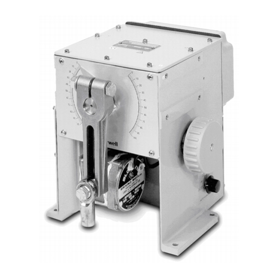
Figure 1-1 10260A Actuator
Figure 1-2 10260A Internal View
2 Specifications and Model Selection Guide
Introduction
Specifications
Model Selection Guide
3 Installation
Introduction
Before Starting
Unpacking
Site Selection
Outline Dimension Drawings
Figure 3-1 Outline and Dimensions of 10261A, -62A, -64A, -66A, -67A, -68A, and -69A Actuators
Figure 3-2 Outline and Dimensions of 10263A and 10265A Actuators
Mechanical Installation
General
Linkage Set-Up
Figure 3-3 Constant Torque Linkage
Figure 3-4 Constant Torque Profile
Figure 3-5 Variable Torque Linkage
Figure 3-6 Variable Torque Profile
Figure 3-7 Turnbuckle Linkage Kit
Figure 3-8 Pipe Linkage Kit
Figure 3-9 Standard 5" Crank Arm
Projecting Scale Option
Figure 3-10 Projecting Scale Option
Electrical Installation
General Wiring Recommendations
Table 3-1 Recommended Minimum Wire Size
Customer Connections
Figure 3-11 Customer Terminal Connections (Non-Contact Sensor)
Figure 3-12 Customer Terminal Connections (Film Potentiometer)
Power Connections
CE Wiring
0/4-20 Ma, 0/1-5 VDC Input Signal Connections
0/4-20 Ma, 0/1-5 VDC Feedback Signal Connections
Slidewire Emulator Connections
Figure 3-13 Slidewire Connections
4 Calibration Procedures
Overview
Setting End-Of-Travel Limit Switches (Actuators Mfd. Pre-1/1/03)
Setting End-Of-Travel Limit Switches (Actuators Mfd. after 1/1/03)
Setting Auxiliary Switches (Actuators Mfd. Pre-1/1/03)
Figure 4-1 Location of Auxiliary Switches
Figure 4-2 End of Travel Limit Switch Settings
Figure 4-3 Auxiliary Switch Settings
Setting Auxiliary Switches (Actuators Mfd. after 1/1/03)
Non-Contact Sensor
Figure 4-4 Location of NCS Assembly
Motor Positioner Board
Overview
Available Adjustments
Table 4-1 Available Adjustments
ZERO and SPAN Adjustments
Fail-Safe Settings; Loss of Signal (L.O.S.)
Filter Settings
Deadband and Sensitivity Settings
Figure 4-5 Motor Positioner Board
Output Board Calibration
0/4-20 Ma PWA Output Board
Figure 4-6 0/4-20 Ma PWA Output Board
Slidewire Emulation
Figure 4-7 Slidewire Emulation Board
Reversal of Direction (Non Contact Sensor)
Reversal of Direction (Film Potentiometer)
Figure 4-8 Switch Jumper for Reversal
5 Start-Up/Operation
Introduction
Operations Checklist
6 Other Control Functions
Split Range
Master/Slave Arrangement
Basic Flow Control
Figure 6-1 Flow Diagram
Figure 6-2 Interconnection Diagram
Proportional Flow Using Multiple Actuators
Figure 6-3 Proportional Flow Using Multiple Actuators
Figure 6-4 Multiple Actuator Interconnection Diagram
Split Valve Configuration
Figure 6-5 Interconnection Diagram
7 Maintenance
Introduction
Basic Maintenance
Main Gear Lubrication
Spur Gear Lubrication
Non-Contact Sensor
Motor Positioner
Replacing the Fuses
8 Replacement/Recommended Spare Parts
Introduction
Motor Kits
Idler Gear Kits
Non-Contact Sensor, Film Potentiometer, Output Board Limit/Aux Switch and CAM Kits
Linkage Parts/Kits
Accessories
Non-Contact Position Sensor Field Upgrade Kits
Honeywell Actuator Linkage Analysis Software (HAL)
Replacement Fuses (Not for Sale)
Film Potentiometer Upgrade Kits
9 Troubleshooting
Introduction
Troubleshooting Procedures
Table 9-1 Observable Symptoms of Failure
Actuator Current Output Does Not Function
Table 9-2 Troubleshooting Current Output
Actuator Slidewire Output Does Not Function
Table 9-3 Troubleshooting Slidewire Output
Actuator CW/CCW Operation Is Not Correct
Table 9-4 Troubleshooting CW/CCW Operation
Actuator Does Not Control to the Proper Position
Table 9-5 Troubleshooting Control Action on Actuator
Auto/Manual Switch Does Not Operate Correctly
Table 9-6 Troubleshooting the Auto /Manual Switch
Actuator CW/CCW Switch Does Not Operate Correctly
Table 9-7 Troubleshooting the CW/CCW Switch
Actuator Up/Down Action Does Not Operate Correctly
Table 9-8 Troubleshooting the Up/Down Actuator Action
Advertisement
Quick Links
1
Product Description
2
Slidewire Emulation
Download this manual
®
10260A HercuLine
Actuator
Installation, Operation and Maintenance
Manual
ISO 9002
62-86-25-06
Rev. 6
2/03
Industrial Measurement and Control
Table of
Contents
Previous
Page
Next
Page
1
2
3
4
5
Advertisement
Table of Contents
Troubleshooting
TROUBLESHOOTING
79
Actuator Current Output does not function
80
Actuator Slidewire Output does not function
81
Actuator CW/CCW operation is not correct
82
Actuator does not control to the proper position
83
Auto/Manual Switch does not operate correctly
84
Actuator CW/CCW Switch does not operate correctly
85
Need help?
Do you have a question about the HercuLine 10260A and is the answer not in the manual?
Ask a question
Questions and answers
Related Manuals for Honeywell HercuLine 10260A
Controller Honeywell HercuLine 2000 Series Installation, Operation And Maintenance Manual
(128 pages)
Controller Honeywell Herculine 2000 Series Quick Start Manual
(10 pages)
Controller Honeywell HEGSA002 User Manual User Manual
Ultrakey controller (74 pages)
Controller Honeywell 2000 Series Installation, Operation And Maintenance Manual
Herculine 2000 series (130 pages)
Controller Honeywell HercuLine 10260S Installation, Operation And Maintenance Manual
Smart actuator (122 pages)
Controller Honeywell HercuLink User Manual
(40 pages)
Controller Honeywell TrueZONE HZ311, HZ322, HZ432 Manual
Zoning system design manual (13 pages)
Controller Honeywell HC900 Installation And User Manual
Honeywell hc900 hybrid controller installation and user guide (228 pages)
Controller Honeywell HC900 Installation And User Manual
Process controller (264 pages)
Controller Honeywell HC900 User And Installation Manual
Process and safety controller (274 pages)
Controller Honeywell HC900 Reference Manual
Hybrid control designer (456 pages)
Controller Honeywell HC900 Safety Manual
Process & safety controller (74 pages)
Controller Honeywell HC900 User Manual
Process controller (112 pages)
Controller Honeywell HVC0001 Owner's Manual
Programmable bath fan control (10 pages)
Controller Honeywell THR0924 Manual
Wireless radiator controller (13 pages)
Controller honeywell TheraPro HR90 Owner's Manual
Electronic radiator controller (40 pages)
This manual is also suitable for:
Herculine 10261a
Herculine 10262a
Herculine 10264a
Herculine 10266a
Herculine 10267a
Herculine 10268a
...
Show all
Herculine 10269a
Herculine 10263a
Herculine 10265a
Herculine 10262a-1-0-00-0-00003-100-00
Herculine 10262a-1-0-04-2-00000-000-00
Herculine 10263a-1-1-03-7-00200-000-00
Herculine 10264a-1-0-00-0-00000-000-00
Herculine 10264a-1-1-01-2-00000-000-00
Herculine 10264a-4-1-00-5-01100-012-00
Herculine 10266a-1-0-01-2-00010-000-00
Herculine 10266a-1-1-05-9-00002-100-00
Herculine 10267a-1-0-03-5-00010-000-00
Herculine 10268a-1-0-01-0-00202-000-00
Herculine 10269a-1-1-05-2-00010-100-00
Table of Contents
Print
Rename the bookmark
Delete bookmark?
Delete from my manuals?
Login
Sign In
OR
Sign in with Facebook
Sign in with Google
Upload manual
Upload from disk
Upload from URL


Need help?
Do you have a question about the HercuLine 10260A and is the answer not in the manual?
Questions and answers