Honeywell HC900 User And Installation Manual
Process and safety controller
Hide thumbs
Also See for HC900:
- Reference manual (456 pages) ,
- Installation and user manual (264 pages) ,
- User manual (112 pages)

Related Manuals for Honeywell HC900


Summary of Contents for Honeywell HC900
- Page 1 HC900 Process & Safety Controller User and Installation Manual Doc. No.: 51-52-25-154 Revision: Date: 21 April 2017...
- Page 2 However, we assume no responsibility for its use. While we provide application assistance personally, through our literature and the Honeywell web site, it is up to the customer to determine the suitability of the product in the application.
- Page 3 About This Document Abstract This document provides descriptions and procedures for the installation, operation and maintenance of the HC900 Process Controller hardware. References The following list identifies all documents that may be sources of reference for material discussed in this publication.
- Page 4 Phone Number United States and 1-800-343-0228 Customer Service Honeywell Inc. Canada 1-800-423-9883 Global Technical Support Email: (Sales) FP-Sales-Apps@Honeywell.com Global Email Support Honeywell Process Solutions or (TAC) hfs-tac-support@honeywell.com HC900 Process & Safety Controller User and Installation Manual Revision 6 21 April 2017...
- Page 5 Revision 6 HC900 Process & Safety Controller User and Installation Manual 21 April 2017...
- Page 7 Chassis Ground. Identifies a connection to the chassis or frame of the equipment shall be bonded to Protective Earth at the source of supply in accordance with national and local electrical code requirements. Revision 6 HC900 Process & Safety Controller User and Installation Manual 21 April 2017...
- Page 8 This page is intentionally left blank. viii HC900 Process & Safety Controller User and Installation Manual Revision 6 21 April 2017...
-
Page 9: Table Of Contents
Hardware and wiring requirements for safety configuration ..............62 System Monitor Function Blocks ......................64 Rack Installation ......................65 Overview ..............................65 Mount Racks ............................68 Assemble Controller Rack ........................70 Revision 6 HC900 Process & Safety Controller User and Installation Manual 21 April 2017... - Page 10 Overview .............................. 127 Wiring and cabling..........................127 Connecting the Operator Interface to the Controller ................131 Connecting the HC900 Controller to a PC with the Designer Software ..........132 Connecting the HC900 Controller to Modbus device(s) ..............152 Operating Characteristics .................... 155 Introduction ............................
- Page 11 Analog Input ............................218 Relay Output ............................225 Analog Input/Digital Input/Digital Output/Analog Output ..............229 Declaration of Conformity .................... 255 ATEX Certification ....................... 256 INDEX ......................... 257 Revision 6 HC900 Process & Safety Controller User and Installation Manual 21 April 2017...
- Page 12 Table 39 – Installing Backup Battery (CPU not initialized) .................. 204 Table 40 – Replacing a Backup Battery (CPU Powered)) ..................205 Table 41 - HC900 PV Input Types and Ranges ..................... 211 Table 42 – System Size and Availability Summary ....................214 Table 43 –...
- Page 13 Figures Figure 1 – Small HC900 Controller Configuration ....................9 Figure 2 – Expanded HC900 Controller Configuration (C50/C70 CPU only) ............10 Figure 3 – Single process with redundancies ......................11 Figure 4 – Configuration with Multiple Controllers ....................18 Figure 5 –...
- Page 14 Figure 74 – Quadrature, Single Ended, External Power Wiring ................124 Figure 75 – Quadrature, Differential, HC900 Power Wiring................. 124 Figure 76 – Quadrature, Single Ended, HC900 Power Wiring ................125 Figure 77 – A Direct Serial RS-232 Connection ....................133 Figure 78 –...
-
Page 15: Introduction
Introduction - Purpose Introduction Purpose This publication describes the installation, operation, and maintenance of the Honeywell HC900 Process Controller. This publication includes the following sections. Chapter Title Page Content Introduction Model numbers, how to verify component compatibility, function description of components, feature summary. -
Page 16: Model Selection Guide
Digital Output, 120/240 VAC (8 channel) 900K01 – 0101 Pulse/Frequency/Quadrature *Reference only – For the latest Hardware and firmware revision numbers can be found at: https://www.honeywellprocess.com/library/support/Public/Downloads/HC900- SafetyControllerModulesRevisions.zip HC900 Process & Safety Controller User and Installation Manual Revision 6 21 April 2017... - Page 17 Ethernet Switching Hub (8 Ports) 51452041 – 501 24 VDC Power Supply *Reference only – For the latest Hardware and firmware revision numbers can be found at: https://www.honeywellprocess.com/library/support/Public/Downloads/HC900- SafetyControllerModulesRevisions.zip Revision 6 HC900 Process & Safety Controller User and Installation Manual 21 April 2017...
- Page 18 120/240 VAC, 28 W 900P02-0101 24 VDC, 60 W 900P24-0101 *Reference only – For the latest Hardware and firmware revision numbers can be found at: https://www.honeywellprocess.com/library/support/Public/Downloads/HC900- SafetyControllerModulesRevisions.zip HC900 Process & Safety Controller User and Installation Manual Revision 6 21 April 2017...
- Page 19 Digital Output, 120/240 VAC (8 channel) 900H03-0202 Digital Output, 24VDC (32 channel) 900H32-0102 Pulse/Freq/Quad (4chan, 1Quad) 900K01-0201 May be used in Safety systems on the Process Worksheet ONLY. Revision 6 HC900 Process & Safety Controller User and Installation Manual 21 April 2017...
-
Page 20: Revision
900C71 – 00XX-00 900C72 – 00XX-00 900C71R – 0000-XX 900C72R – 0000-XX 900RSM – 0001 900C73R – 0000-XX 900C53 – 00XX-00 HC900 Process & Safety Controller User and Installation Manual Revision 6 21 April 2017... - Page 21 900C70S - 0360-00 900C75S-0360-00 900S50S - 0360-00 900S75S-0360-00 *Reference only – For the latest Hardware and firmware revision numbers can be found at: https://www.honeywellprocess.com/library/support/Public/Downloads/HC900- SafetyControllerModulesRevisions.zip Revision 6 HC900 Process & Safety Controller User and Installation Manual 21 April 2017...
- Page 22 Introduction ATTENTION For the Legacy systems, it is specifically mentioned in the guide wherever applicable. The other text is applicable to the new HC900 system. Modems are not qualified with the new HC900 system. Checking HC900 Model Numbers for Compatibility ATTENTION Be sure to check your model numbers for compatibility before installation.
-
Page 23: Functional Description
It comprises a set of hardware and software modules that can be assembled to satisfy any of a broad range of process control applications. The HC900 Process Controller can consist of a single rack, as indicated in Figure 1, or can be can be networked with other controllers via Ethernet links to expand the dimensions of control over a wider range of unit processes, as indicated in Figure 2. -
Page 24: Figure 2 - Expanded Hc900 Controller Configuration (C50/C70 Cpu Only)
Figure 2 – Expanded HC900 Controller Configuration (C50/C70 CPU only) The HC900 Controller design enables users and OEMs who are adept in system integration to assemble a system that fits a broad range of requirements. Any configuration can be readily modified or expanded as requirements dictate. -
Page 25: Figure 3 - Single Process With Redundancies
Introduction Redundancy Figure 3 – Single process with redundancies Revision 6 HC900 Process & Safety Controller User and Installation Manual 21 April 2017... - Page 26 Scanner 2 module – has 2 ports, one for each CPU connection to I/O. This IO network between the controllers and scanners is considered proprietary with no other Ethernet traffic. HC900 Process & Safety Controller User and Installation Manual Revision 6...
-
Page 27: Feature Summary
USB to RS485 cable must be obtained to support link to PC for 900 Designer configuration tool Can be configured for Modbus RTU, master or slave communications (up to 2000 Ft /600 Meters) Revision 6 HC900 Process & Safety Controller User and Installation Manual 21 April 2017... - Page 28 C70R Legacy and C75/C75S (new model) support up to 10 PC hosts via Modbus/TCP protocol. Peer-to Peer (UDP) communication with up to 32 other HC900 Controllers. C70/C70S and C70R Legacy and C75/C75S (new model) have 2 Ethernet ports for connection to up to 10 PC hosts.
- Page 29 Introduction This page is intentionally left blank. Revision 6 HC900 Process & Safety Controller User and Installation Manual 21 April 2017...
-
Page 31: Components And Architecture
Components and Architecture - Overview Components and Architecture Overview This section provides a description of each of the major components that can be included in an HC900 Controller physical configuration, and indicates some of the methods by which they can be combined. Components The Honeywell HC900 Process Controller includes a set of hardware modules that can be combined and configured as required for a wide range of small to medium process control applications. -
Page 32: Figure 4 - Configuration With Multiple Controllers
Figure 4 – Configuration with Multiple Controllers CAUTION The HC900-expansion I/O link is a private network and the switch used for the interconnection of the HC900 Processor and Scanners must not be connected to any other LAN or WAN. Likewise, no devices other than the HC900 components should be connected to the I/O link Switch. -
Page 33: Table 1 - Descriptions Of Major Components (Figure 4)
Ethernet CAT5 Connects devices in Ethernet Open Connectivity Third-party suppliers or shielded cable network to 900 Control Stations and PC SCADA Honeywell applications. Revision 6 HC900 Process & Safety Controller User and Installation Manual 21 April 2017... -
Page 34: Redundant Components
For new system, RS-485 to USB converter connects galvanically isolated RS-485 port to USB port. Redundant components Figure 5 – Redundant Configuration with multiple I/O racks CAUTION HC900 Process & Safety Controller User and Installation Manual Revision 6 21 April 2017... - Page 35 The HC900-expansion I/O link is a private network and the switch used for the interconnection of the HC900 Processor and Scanners must not be connected to any other LAN or WAN. Likewise, no devices other than the HC900 components should be connected to the I/O link Switch. Failure to comply will cause communication failures on the I/O link causing I/O modules to go in and out of their failsafe settings.
-
Page 36: Table 2 - Descriptions Of Major Redundancy Components
Third-party suppliers or (15.24m) (PC modem cable if used with Modems.) Honeywell For new systems, RS-485 to USB converter, connects galvanically isolated RS-485 port to USB port. HC900 Process & Safety Controller User and Installation Manual Revision 6 21 April 2017... -
Page 37: Hardware Components
Note: The HC900 is equipped with an Ethernet port as a standard feature (two Ethernet ports on the C70 & C75 CPU). These ports can function simultaneously as slave and master communications ports. The dual Ethernet ports (C70 & C75 CPU’s) can be configured for redundant operation to a host. -
Page 38: Figure 7 - Redundant Controller Rack Components
HC900 Redundant Controller Rack A HC900 Redundant Controller is shown in the following figure. Rack Redundancy Switch Module (RSM) . Interface between Lead/Reserve controllers. Lead/Reserve controllers. Two C75 CPUs, designated “CPU-A” (left), “CPU-B” (right). Two 900P01-xxxx or 900P02-xxxx Power Supplies. -
Page 39: Figure 8 - I/O Expansion Rack Components
7. Power Status Module (PSM) (req’d if using Reserve Power Supply) 8. Reserve Power Supply (optional). Available in 8- or 12- slot racks. Figure 8 – I/O Expansion Rack Components Revision 6 HC900 Process & Safety Controller User and Installation Manual 21 April 2017... -
Page 40: Figure 9 - Rack Options
8 and 12 slot I/O racks can be modified with additional slots for optional Reserve Power Supply and Power Status Module. Note: You can install redundant power on any 8 or 12 slot I/O rack. Figure 9 – Rack Options HC900 Process & Safety Controller User and Installation Manual Revision 6 21 April 2017... -
Page 41: Figure 10 - Power Supply
P24 power supply provides 5VDC and 24VDC to satisfy the power requirements of a single controller with I/O, a Remote I/O rack or a Redundant C75 CPU. The 60 watt capacity requires minimal de-rating of the available HC900 I/O modules. -
Page 42: Figure 11 - Power Status Module (Psm)
When the status is off, either the power supply is off or the voltages are out of tolerance. Figure 11 – Power Status Module (PSM) HC900 Process & Safety Controller User and Installation Manual Revision 6 21 April 2017... -
Page 43: Figure 12 - Controller Module
Figure 12 – Controller Module Redundant controller rack contains two C75s or C75Ss. Left CPU is designated CPU-A, right CPU is CPU-B; either CPU can be Lead. Revision 6 HC900 Process & Safety Controller User and Installation Manual 21 April 2017... -
Page 44: Figure 13 - Redundancy Switch Module
Controller Module (or to a port on a Switch that connects to the Controller Module) LED status/diagnostic indicators for communications functions. Figure 14 – Scanner 1 Module HC900 Process & Safety Controller User and Installation Manual Revision 6 21 April 2017... -
Page 45: Figure 15 - Scanner 2 Module
8 point Universal Analog Input module. Galvanically isolated input to chassis and input to input. With the exception of RTD types which has four groups of isolation 1-2,3-4,5-6,7-8. 4 channel Pulse/Frequency/Quadrature I/O module. Galvanically isolated channel to chassis. Revision 6 HC900 Process & Safety Controller User and Installation Manual 21 April 2017... -
Page 46: April
For the new system, a PC can be connected to the controller via the RS-485 to USB cable connected to RS485 Port , which can be connected to external Honeywell qualified RS485 to USB converter, and can also be networked to the controller via the Ethernet 10/100Base-T Open Connectivity Network port. -
Page 47: I/O Network
Figure 17 – RS-232 Modem Devices I/O Network I/O Expansion Network (C50 and C50S/C70 and C70S CPU only) Examples of HC900 Controller I/O expansion configurations are shown in Figure 18. Revision 6 HC900 Process & Safety Controller User and Installation Manual... -
Page 48: Figure 21 - Hc900 Controller Configurations
Scanner Module. ATTENTION: For 2 or more I/O expansion racks a switch is required. Use only Honeywell recommended switches (part no. 50008930-001, 50089785-001). The total number of switches is limited to 2 in series between a CPU and its scanners. -
Page 49: I/O Implementation Requirements Include
Controller Module and in each Scanner Module included in the HC900 system. The controller examines the control strategy stored in its memory, verifies that the physical configuration (Rack Numbers and I/O Module type- by Module Number) matches the stored control strategy, and establishes communication with each of the I/O modules in each of the I/O racks. - Page 50 Peer-to-peer communication enables any given HC900 Controller to request a peer relationship with up to 32 other HC900 Controllers on the same subnet; other controllers can request a peer relationship with the controller. The total number of peers that a controller can have a relationship with is 32. Peer-to-peer communication uses the Ethernet Open Connectivity network and employs standard User Datagram Protocol (UDP) for fast and efficient transfer of information.
-
Page 51: Figure 22 - Modular Network Structure
WAN (Wide Area Network) that is network-connected to the controller. Each HC900 Controller has 5 or 10 “sockets” (software and memory resources), each of which can service data requests from any networked PC on a client (host)/server (controller) basis. The sockets are available on a first-come, first-served basis. -
Page 52: Figure 23 - Modbus/Tcp Framing
The HC900 Controller uses either Modbus/TCP or Modbus RTU, not ASCII. The “fixed” Modbus mapping structure for the HC900 Controller is based on the mapping structure employed in Honeywell’s UMC800 Controller, and the function codes and methods for parameter access are also virtually identical. - Page 53 OPC server/client software (various; available from Kepware and others) : The items in this list are not sold by Honeywell. They have not all been tested and certified by Note Honeywell, and are not necessarily recommended or endorsed by Honeywell for any specific use.
- Page 54 Ethernet Open Connectivity network. In other cases, the HC900 Controller will be a member of a Local Area Network (LAN) as indicated in Figure 19. The HC900 controller LAN may be very simple, or it may include many devices in a complex and very sophisticated structure. In any case, it must always be regarded as a single, modular entity that can be protected from intrusion by any other networking device to which this LAN is connected.
-
Page 55: Figure 24 - Typical Installation Using A Cable Modem
Figure 21 – Typical installation using a Cable Modem Revision 6 HC900 Process & Safety Controller User and Installation Manual 21 April 2017... -
Page 56: Serial Ports
Only one master port at a time; can’t have both serial ports as master ports. Modbus master ports default to slave ports, ELN protocol when CPUs are in Program mode. Baud rates to 115,200 HC900 Process & Safety Controller User and Installation Manual Revision 6 21 April 2017... -
Page 57: Table 3 - Serial Port Dip Switch Settings
DIP switches. If you push too hard you could damage the switches or nearby circuitry. Avoid using pencils because the point could break and cause damage. Table 3 – Serial port DIP switch settings Figure 23 – Serial Ports DIP Switch default settings Revision 6 HC900 Process & Safety Controller User and Installation Manual 21 April 2017... -
Page 58: Network And Security Planning
This guide is primarily intended for engineers, system administrators, and other technical staff who are responsible for planning the configuration and maintenance of a HC900 system. Therefore, it is assumed that the user must have technical knowledge and familiarity with the following: ... -
Page 59: Pre-Installation Planning
Electrical considerations: controller grounding, CE conformity, grouping wires, master control relay for emergency shutdown (see page 56) System monitor function blocks (see page 62) Revision 6 HC900 Process & Safety Controller User and Installation Manual 21 April 2017... -
Page 60: Ac Power Supply Selection For Racks With I/O
340 mA 0 mA DC Digital Output (32 pts) 235 mA 0 mA Relay Output (8 pts) 110 mA 100 mA Pulse/Frequency/Quadrature** ( 110 mA 250 mA HC900 Process & Safety Controller User and Installation Manual Revision 6 21 April 2017... - Page 61 8. Is the result of 7 less than 28? Yes/No If the answer to 8 is Yes, use power supply 900P02-0001 If the answer to 8 is No, use power supply 900P01-0001 Revision 6 HC900 Process & Safety Controller User and Installation Manual 21 April 2017...
-
Page 62: Dc Power Supply
Figure 24 and Figure 25. Vertical spacing of racks, which is required for rack ventilation and for routing wires, is shown in Figure 26. Figure 24 – Rack Dimensions HC900 Process & Safety Controller User and Installation Manual Revision 6 21 April 2017... -
Page 63: Figure 27 - Rack Dimensions With Reserve Power Supply
Figure 25 – Rack Dimensions with reserve power supply Revision 6 HC900 Process & Safety Controller User and Installation Manual 21 April 2017... -
Page 64: Figure 28 - Vertical Spacing Of Racks (All Models)
Figure 26 – Vertical Spacing of Racks (all models) HC900 Process & Safety Controller User and Installation Manual Revision 6 21 April 2017... -
Page 65: Remote Termination Panels
For details see page 217. Environment The HC900 Controller must be mounted in suitable equipment enclosures. That is, all components such as the Controller rack, I/O Racks, and the 900CS Control Station manufactured by Honeywell must be mounted in approved furniture designed for industrial applications. -
Page 66: Heat Rise De-Rating
32 pt DC In (@ 32V) 16 pt DC Out 32 pt DC Out AC In (@120V) AC In (@240V) AC/DC In AC Out 12.0 13.1 HC900 Process & Safety Controller User and Installation Manual Revision 6 21 April 2017... -
Page 67: Figure 29 - Ac Input Module De-Rating
Figure 27 – AC Input Module de-Rating Figure 28 – Power Supply de-Rating Revision 6 HC900 Process & Safety Controller User and Installation Manual 21 April 2017... -
Page 68: Cable/Wiring Distance Planning
With redundant CPUs, when using 2 or more I/O racks an Ethernet switch is required between each CPU and the I/O racks. Use Honeywell-approved switches only. (see page 215) Maximum of 2 switches between each CPU’s I/O port and all I/O racks. - Page 69 Use care to ensure that the cable drain wire is securely connected to the shield of the RJ45 connector when the cable is crimped. Reference the manufacturer’s instructions. Revision 6 HC900 Process & Safety Controller User and Installation Manual 21 April 2017...
-
Page 70: Electrical Considerations
PROTECTIVE BONDING (grounding) of this controller and the enclosure in which it is installed shall be in accordance with National Electrical Code (ANSI/NFPA 70) and with local electrical codes. Figure 29 – Cabinet Wiring, Single Chassis HC900 Process & Safety Controller User and Installation Manual Revision 6 21 April 2017... -
Page 71: Figure 32 - Cabinet Wiring, Multiple Chassis
Figure 30 – Cabinet Wiring, Multiple Chassis Revision 6 HC900 Process & Safety Controller User and Installation Manual 21 April 2017... -
Page 72: Figure 33 - Redundant Power Supplies Each With External Fuse And Switch
For P02 power supply, use 2.5A, slow-blow for 115VAC operation; 2.0A, slow-blow for 230VAC operation. For P24 power supply use 7.0A slow-blow. Figure 31 – Redundant power supplies each with external fuse and switch HC900 Process & Safety Controller User and Installation Manual Revision 6 21 April 2017... -
Page 73: Table 5 - Guidelines For Grouping Wires
Slidewire feedback circuit wiring Communications Low voltage Low voltage alarm relay output wiring (<50 Vdc/Vac) Low voltage wiring to solid state type control circuits Revision 6 HC900 Process & Safety Controller User and Installation Manual 21 April 2017... - Page 74 Class 1, Division 2 Installations DO NOT REMOVE OR REPLACE MODULES WHILE CIRCUIT IS LIVE UNLESS THE AREA IS KNOWN NOT TO CONTAIN FLAMMABLE VAPORS. HC900 Process & Safety Controller User and Installation Manual Revision 6 21 April 2017...
-
Page 75: Figure 34 - Master Control Relay Wiring Example
Figure 32 – Master Control Relay Wiring Example Revision 6 HC900 Process & Safety Controller User and Installation Manual 21 April 2017... -
Page 76: Hardware And Wiring Requirements For Safety Configuration
36 or common for multiple channel outputs as shown in figure 35 and 36. The series output must be configured to operate when the DO-V’s or AO-V’s Fail pin or VFail pin goes “ON”. HC900 Process & Safety Controller User and Installation Manual Revision 6... -
Page 77: Figure 36 - Individual Series Do Connections
High side (relay sinks power). DI Sense is NOT inverted when Load is located on Low side ( relay sources power). Figure 35 – Common Series DO connections Revision 6 HC900 Process & Safety Controller User and Installation Manual 21 April 2017... -
Page 78: System Monitor Function Blocks
Figure 36 – Series Relay for Analog Outputs- System Monitor Function Blocks The HC900 Controller includes function blocks that enable the user to monitor the status of system functions. When constructing a control configuration, consider adding the following monitoring function blocks to the control strategy: ... -
Page 79: Rack Installation
Rack Installation Overview This section contains procedures for installing one or more HC900 Controllers. It is recommended that the information in this section be reviewed before beginning the installation. Familiarity with the overall procedure will help to prevent errors and will promote efficiency in general. ABS installations require additional protection from the environment and must be installed in a grounded metal enclosure. -
Page 80: Table 7 - Site And Equipment Preparation
Sheet metal screws, steel #10 or M4, for mounting racks in enclosures (4 screws for 4-slot racks, 8 screws for 8- or 12-slot racks) HC900 Process & Safety Controller User and Installation Manual Revision 6 21 April 2017... - Page 81 Step Procedure Reference Install (or verify correct installation of) enclosures for HC900 Mount Racks Controllers and ancillary equipment: Table 8 – Mount Rack Mounting rails or flat-panels (for cabinet with multiple HC900 Chassis): grounding bus barrier strip for AC power ...
-
Page 82: Mount Racks
M4) screws. Note: Always mount racks as shown above. That is, never mount vertically, or with backplane horizontal. Remove the rack from the enclosure. HC900 Process & Safety Controller User and Installation Manual Revision 6 21 April 2017... - Page 83 Note: You may find it easier to postpone this step until after all components have been installed in the rack. Repeat for each rack in your system. Revision 6 HC900 Process & Safety Controller User and Installation Manual 21 April 2017...
-
Page 84: Assemble Controller Rack
Do not remove Yellow/Green wire from grounding stud on the power supply. Failure to comply with these instructions could result in death or serious injury. HC900 Process & Safety Controller User and Installation Manual Revision 6 21 April 2017... -
Page 85: April
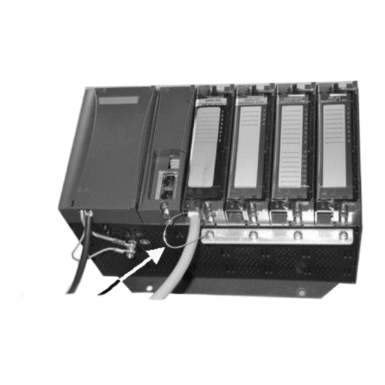
It is measured from the backplane. Image shows strain relief Revision 6 HC900 Process & Safety Controller User and Installation Manual 21 April 2017... - Page 86 Install under power after the controller configuration is complete. (For more information, refer to Battery Installation/Replacement, page 203.) I/O will be installed later. See Page 77. HC900 Process & Safety Controller User and Installation Manual Revision 6 21 April 2017...
-
Page 87: Table 10 - Assemble C75 Controller Rack
(For more information, refer to Battery Installation/Replacement, page 203.) Insert the RSM in the middle See figure in step 1. slot and attach with screws at top and bottom. Revision 6 HC900 Process & Safety Controller User and Installation Manual 21 April 2017... -
Page 88: Assemble I/O Expansion Racks
1 in figure above. See Table 9 steps 1 and 2 for details. Insert the PSM between the 2 power supplies. Fasten it in place with screws at top and bottom. HC900 Process & Safety Controller User and Installation Manual Revision 6 21 April 2017... - Page 89 Then, for each I/O expansion rack, insert the Scanner Module immediately to the right of the Power Supply, and secure it in place with the two captured screws in the faceplate. Revision 6 HC900 Process & Safety Controller User and Installation Manual 21 April 2017...
- Page 90 Step Procedure Comments/References I/O will be installed later. See Page 78. HC900 Process & Safety Controller User and Installation Manual Revision 6 21 April 2017...
- Page 91 This page has been intentionally left blank Revision 6 HC900 Process & Safety Controller User and Installation Manual 21 April 2017...
-
Page 92: I/O Module Installation And Wiring
HC900 Controller. Do not operate the controller without a Protective Earth connection. Failure to comply with these instructions could result in death or serious injury. HC900 Process & Safety Controller User and Installation Manual Revision 6 21 April 2017... -
Page 93: Figure 40 - Terminal Block Styles
Any of the color-coded labels will fit into the door of any terminal block. Use care to ensure that all hardware components match each other, and also match the control strategy in the configuration file. Revision 6 HC900 Process & Safety Controller User and Installation Manual 21 April 2017... -
Page 94: Remote Termination Panel (Rtp)
Remote Termination Panel (RTP) The optional Remote Termination Panel (RTP) provides an easy way to connect the HC900 controller to the field wiring. The RTP integrates some of the typical externally connected components, reducing wiring and setup time. It also minimizes the need for multiple wires under a single screw connection by expanding the connectivity of the shared terminals of the I/O modules. -
Page 95: Figure 41 - Signal-Wire Grounding
I/O module. Figure 40 – Wire-Shield Grounding Revision 6 HC900 Process & Safety Controller User and Installation Manual 21 April 2017... -
Page 96: Figure 43 - Terminal Block Jumper Installation
V+ terminals on the DC Output Module. Refer to the wiring information on each module, given in this section of this manual. Figure 41 – Terminal Block Jumper Installation HC900 Process & Safety Controller User and Installation Manual Revision 6 21 April 2017... -
Page 97: Removal And Insertion Under Power (Riup)
I/O module, particularly in a system that is actively controlling a process. In legacy systems, all of the I/O Module types in the HC900 Controller System include the Removal and Insertion Under Power (RIUP) feature. That is, while the rack is powered, any of the I/O Modules can be removed or inserted: ... -
Page 98: I/O Module Installation Procedures
(tagname side out) into the hinged door for each I/O Module. Slotted tabs, molded into the door at top and bottom, hold the label in place. HC900 Process & Safety Controller User and Installation Manual Revision 6 21 April 2017... - Page 99 "key-tabs" in the pattern that identifies each module type. (For a diagram of each key-tab pattern, use the I/O Modules and/or the diagram shown next page. Revision 6 HC900 Process & Safety Controller User and Installation Manual 21 April 2017...
- Page 100 The orientation of the diagrams below corresponds to the picture of the terminal block, shown in the previous picture. Diagrams for I/O Module Key-Tabs 120/240 VAC, 125VDC Same as 120/240 Vac IN HC900 Process & Safety Controller User and Installation Manual Revision 6 21 April 2017...
- Page 101 Note: 24VDC external power is required if using 6 or more 8-pt. AO modules or 3 or more 16-pt. AO modules. A small slotted screwdriver or paperclip works well; avoid using pencils. 8-16 Analog output Channels require loop power for open loop detection. Revision 6 HC900 Process & Safety Controller User and Installation Manual 21 April 2017...
- Page 102 Single ended (factory setting): 1 and 2 (SINGLE) = ON, 3 and 4 (DIFF) = OFF Differential: 1 and 2 (SINGLE) = OFF, 3 and 4 (DIFF) = ON HC900 Process & Safety Controller User and Installation Manual Revision 6 21 April 2017...
- Page 103 Rack. Form a bend in each wire to provide strain relief, and secure the wire bundle with the tie. Euro Terminal Block Revision 6 HC900 Process & Safety Controller User and Installation Manual 21 April 2017...
- Page 104 Block cover, Part number the same manner as a Terminal Block (with captured screws at 900TNF-0001. top and bottom). Blank labels are provided for mounting in the hinged door. HC900 Process & Safety Controller User and Installation Manual Revision 6 21 April 2017...
-
Page 105: I/O Terminal Block Wiring Diagrams
For example, the current source for the RTD input at channel one (terminals 1 and 2) is terminal 3 (I 1 & 2). This same current source (I 1 & 2) is also used for an RTD input at channel two (terminals 4 and 5). Revision 6 HC900 Process & Safety Controller User and Installation Manual 21 April 2017... -
Page 106: Figure 44 - Rtd Inputs
Using switches at field devices disconnect the field wiring from power sources before servicing. Failure to comply with these instructions could result in death or serious injury. HC900 Process & Safety Controller User and Installation Manual Revision 6 21 April 2017... -
Page 107: Figure 45 - Universal Analog Input Wiring Diagram
Figure 43 – Universal Analog Input Wiring Diagram Revision 6 HC900 Process & Safety Controller User and Installation Manual 21 April 2017... -
Page 108: Figure 46 - Examples Of Rtd Input Wiring
Figure 44 – Examples of RTD Input Wiring HC900 Process & Safety Controller User and Installation Manual Revision 6 21 April 2017... -
Page 109: Figure 47 - Analog Input Wiring - Eight Tcs
Figure 45 – Analog Input Wiring - Eight TCs Revision 6 HC900 Process & Safety Controller User and Installation Manual 21 April 2017... -
Page 110: Figure 48 - Analog Input Wiring - Eight Resistance Inputs
Figure 46 – Analog Input Wiring - Eight Resistance Inputs HC900 Process & Safety Controller User and Installation Manual Revision 6 21 April 2017... -
Page 111: Figure 49 - Analog Input Wiring - Eight Rtds
Resistance Temperature Device Inputs Figure 47 – Analog Input Wiring - Eight RTDs Revision 6 HC900 Process & Safety Controller User and Installation Manual 21 April 2017... -
Page 112: Figure 50 - Analog Input Wiring - Slidewire (Position Proportion Block)
Slidewires Figure 48 – Analog Input Wiring – Slidewire (Position Proportion Block) HC900 Process & Safety Controller User and Installation Manual Revision 6 21 April 2017... -
Page 113: Figure 51 - 16 Point High Level Analog Input Wiring
An example of Analog Output Module wiring is shown in Figure 50. Specifications for this module and for other modules are given in the Specifications manual. SIL applications require an external series relay used to ensure outputs achieve failsafe action. See HC900 Process & Safety Controller Safety Manual for additional details. -
Page 114: Figure 52 - 4 Channel Analog Output Wiring Diagram
Examples of high level Analog Output Module wiring are shown in Figure 51 and Figure 52. Specifications for this module and for other modules are given in the Specifications manual. SIL applications require an external series relay used to ensure outputs achieve failsafe action. See HC900 Process & Safety Controller Safety Manual for additional details. -
Page 115: Figure 53 - 8 Channel Analog Output Wiring Diagram
OUT 5+ OUT 6+ OUT 5- OUT 6- OUT 7+ OUT 8+ OUT 7- OUT 8- 24VDC+ 24VDC- Figure 51 – 8 channel Analog Output Wiring Diagram Revision 6 HC900 Process & Safety Controller User and Installation Manual 21 April 2017... -
Page 116: Figure 54 - 16 Channel Analog Output Wiring Diagram
Using switches at field devices disconnect the field wiring from power sources before servicing. Failure to comply with these instructions could result in death or serious injury. HC900 Process & Safety Controller User and Installation Manual Revision 6 21 April 2017... -
Page 117: Figure 55 - Dc Input Module Wiring Diagram
Figure 53 – DC Input Module Wiring Diagram Revision 6 HC900 Process & Safety Controller User and Installation Manual 21 April 2017... - Page 118 Figure 54 – DC Input Module Jumper HC900 Process & Safety Controller User and Installation Manual Revision 6 21 April 2017...
- Page 119 The AC Input Module has sixteen inputs. An example of AC Input Module wiring is shown in Figure 56. Specifications for this module and for other modules are given in the Specifications section of this manual. Revision 6 HC900 Process & Safety Controller User and Installation Manual 21 April 2017...
- Page 120 Using switches at field devices, disconnect the field wiring from power sources before servicing. Failure to comply with these instructions could result in death or serious injury. Figure 56 – AC Input Module Wiring Diagram HC900 Process & Safety Controller User and Installation Manual Revision 6 21 April 2017...
- Page 121 Figure 57 – AC Input Module Jumper Revision 6 HC900 Process & Safety Controller User and Installation Manual 21 April 2017...
- Page 122 Requires Low Voltage Euro style 36-terminal terminal block. Isolation Inputs must be powered from external voltage sources. Inputs are isolated from each other and from controller power. HC900 Process & Safety Controller User and Installation Manual Revision 6 21 April 2017...
- Page 123 125 VDC 125 VDC External External Legend: Legend: Fuse Fuse Disconnect Disconnect User-Supplied Safety Devices User-Supplied Safety Devices Figure 58 – AC/DC Isolated Input Module Wiring Revision 6 HC900 Process & Safety Controller User and Installation Manual 21 April 2017...
- Page 124 Figure 59. SIL applications require an external blocking diode used to insure inputs are protected from ground faults. See HC900 Process & Safety Controller Safety Manual for additional details. Specifications for the Contact Input Module and other modules are given in the Specifications manual.
- Page 125 DC output load, and the negative side of the load is switched internally in the module. SIL applications require an external series relay used to ensure outputs achieve failsafe action. See HC900 Process & Safety Controller Safety Manual for additional details.
- Page 126 Using switches at field devices disconnect the field wiring from power sources before servicing. Failure to comply with these instructions could result in death or serious injury. HC900 Process & Safety Controller User and Installation Manual Revision 6 21 April 2017...
- Page 127 Figure 60 – DC Output Module Wiring Diagram Revision 6 HC900 Process & Safety Controller User and Installation Manual 21 April 2017...
- Page 128 Figure 61 – DC Output Jumpers HC900 Process & Safety Controller User and Installation Manual Revision 6 21 April 2017...
- Page 129 4 groups of 8 channels. In case of short circuit for any output channel, that whole group of 8 is switched off. Power cycling is not required to reset the module. SIL applications require an external series relay used to ensure outputs achieve failsafe action. See HC900 Process & Safety Controller Safety Manual for additional details.
- Page 130 Using switches at field devices disconnect the field wiring from power sources before servicing. Failure to comply with these instructions could result in death or serious injury. HC900 Process & Safety Controller User and Installation Manual Revision 6 21 April 2017...
- Page 131 Figure 63 – AC Output Module Wiring Diagram Revision 6 HC900 Process & Safety Controller User and Installation Manual 21 April 2017...
- Page 132 Figure 64 – AC Output Module Jumper HC900 Process & Safety Controller User and Installation Manual Revision 6 21 April 2017...
- Page 133 Form-C, and the other four are Form-A. A schematic showing the relationship of individual Form-A relays and Form-C relays to external (user) connections is given in Figure 65. SIL applications require an external series relay used to ensure outputs achieve failsafe action. See HC900 Process & Safety Controller Safety Manual for additional details.
- Page 134 Using switches at field devices disconnect the field wiring from power sources before servicing. Failure to comply with these instructions could result in death or serious injury. Figure 66 – Relay Output Module Wiring Diagram HC900 Process & Safety Controller User and Installation Manual Revision 6 21 April 2017...
- Page 135 The Pulse Output functionality uses the digital output available on the module for outputting pulses. Before installing be sure to set the module DIP switches for differential or single ended. See page 88. Revision 6 HC900 Process & Safety Controller User and Installation Manual 21 April 2017...
- Page 136 Figure 68 – Pulse Counting Wiring Figure 69 – Pulse Output Wiring HC900 Process & Safety Controller User and Installation Manual Revision 6 21 April 2017...
- Page 137 Figure 70 – Frequency Wiring Figure 71 – Quadrature, Differential, External Power Wiring Revision 6 HC900 Process & Safety Controller User and Installation Manual 21 April 2017...
- Page 138 Figure 72 – Quadrature, Single Ended, External Power Wiring Figure 73 – Quadrature, Differential, HC900 Power Wiring HC900 Process & Safety Controller User and Installation Manual Revision 6 21 April 2017...
- Page 139 Figure 74 – Quadrature, Single Ended, HC900 Power Wiring Revision 6 HC900 Process & Safety Controller User and Installation Manual 21 April 2017...
-
Page 141: Communications Installation
All ports are shown. (Availability depends on controller model, see Figure 12 page 29.) Connect communications cabling. For Modbus connections, see page 152. Communication Ports (all ports shown) Revision 6 HC900 Process & Safety Controller User and Installation Manual 21 April 2017... -
Page 142: Table 17 - Links To Controller Communication Ports
RS-485 Modbus slave Belden #9271 (or SIL applications require 3-Plug connector network (controller equivalent) instructions shield drain wire to be is master) connected to grounding bar. HC900 Process & Safety Controller User and Installation Manual Revision 6 21 April 2017... - Page 143 No foreign messaging Scanner 2’s I/O A port. 100Base-T CAT5 cable with RJ- permitted 45 connectors C75 CPU B’s I/O port to Scanner 2’s I/O B port. Revision 6 HC900 Process & Safety Controller User and Installation Manual 21 April 2017...
- Page 144 Scanner 2’s I/O B port. One (1) additional unmanaged switch may be used, for a total of 2 unmanaged switches between CPU B and the I/O racks. HC900 Process & Safety Controller User and Installation Manual Revision 6 21 April 2017...
-
Page 145: Connecting The Operator Interface To The Controller
Connector (3-pin) (Supplied with the equivalent) for C30/C50 controller CPU module) Phoenix 1803581 for C75. 047260 Ferrite cable clamps (Supplied with the operator interface) 089037 Nylon cable ties Revision 6 HC900 Process & Safety Controller User and Installation Manual 21 April 2017... -
Page 146: Connecting The Hc900 Controller To A Pc With The Designer Software
Connecting the HC900 Controller to a PC with the Designer Software To establish communications between the HC900 controller and the Process Control (HC) Designer configuration software use any of the following methods. A. Direct Serial RS-232 connection. See page 133. Direct with RS-485 and RS-485 to USB converter with supplied instructions. - Page 147 PC port and the controller. In general, the faster the baud rate the better the performance, however, your PC may not communicate reliably at the faster baud rates. (Refer to the HC900 Designer Software User’s Guide or its respective on-line help, Setting Up PC Com Ports and Connections - PC Serial Com Port Setup and Utilities Worksheet - Set Controller Serial Port, for details on this step).
-
Page 148: Table 19 - Null Modem Cable Connections
RS-232 Direct Link to PC Configuration Tool (Legacy Controllers) The Controller can be connected directly to the PC, in which case a Null Modem Cable is required. The Null Modem Cable can be ordered from Honeywell (Part# 50004820-501). Cable connections are shown in Table 19. - Page 149 All functions of the Designer Software configuration tool can be performed over this link. Remote access functions include on-line monitoring, configuration upload and download, and firmware upgrade. Figure 76 – RS-232 Remote Access via Modems Revision 6 HC900 Process & Safety Controller User and Installation Manual 21 April 2017...
- Page 150 B. Modem Connection Figure 77 - Modem Connection HC900 Process & Safety Controller User and Installation Manual Revision 6 21 April 2017...
- Page 151 Step Procedure Connect a modem to the HC900 controller’s for a list of approved modems, their settings, and the connection specifics. On the PC, check on the Utilities Worksheet in the HC Designer software to see if the PC modem is properly installed.
- Page 152 Modem requirements Most commercially available modems can be used with the HC900 Controller. The modem must have the following capabilities: RS-232 interface Auto answer Can operate at 1200, 2400, 4800, 9600, 19200, 38400, 57600 baud; recommended 9600 or 19200 or 38400 baud, 8 data bits, 1 stop bit, and no parity ...
- Page 153 Start up a PC terminal program such as Hyperterminal. Configure the PC COM Port for 1200, 2400, 4800, 9600*, 19200*, 38400*, 57600 baud (must match Baud Rate configured in HC900 Controller), no parity, 1 stop bit, and 8 data bits. *recommended Establish communications with the modem.
- Page 154 In the program's terminal window, restore factory defaults by keying-in the following command string: AT &F0 Then, press the ENTER key. The modem should respond with OK. HC900 Process & Safety Controller User and Installation Manual Revision 6 21 April 2017...
- Page 155 Power up the modem and the HC900 Controller. On a remote computer, run Designer Software. Set up Designer Software to dial the HC900 Controller. Verify that communications is established with the remote HC900 Controller. Revision 6 HC900 Process & Safety Controller User and Installation Manual...
- Page 156 Power up the modem and the HC900 Controller. On a remote computer, run Designer software. Set up the PC software to dial the HC900 Controller. Use the PC software "Loop-back" feature to verify that communications are established with the remote HC900 Controller.
- Page 157 Power up the modem and the HC900 Controller. On a remote computer, run Designer software. Set up the PC software to dial the HC900 Controller. Use the PC software "Loop-back" feature to verify that communications are established with the remote HC900 Controller.
- Page 158 Power-up the modem and the HC900 Controller. On a remote computer, run Designer software. Set up the PC software to dial the HC900 Controller. Use the PC software "Loop-back" feature to verify that communications are established with the remote HC900 Controller.
- Page 159 Only use Shielded CAT 5 cable for network connections. See Figure 78 and Table 20. Figure 78 – Dual Networks (see Table 20) ATTENTION: Always observe the wiring/cabling guidelines on page 54. Revision 6 HC900 Process & Safety Controller User and Installation Manual 21 April 2017...
-
Page 160: Table 20 - Dual Network Connections In Figure 80
Connect the Auxiliary Ethernet port of the 900 Control Station to the Ethernet switch, which is assigned to port E2 of the controller CPUs Connect CPU-A S1 port to PC USB port through RS-485 to USB converter (50089787-001) HC900 Process & Safety Controller User and Installation Manual Revision 6 21 April 2017... -
Page 161: Table 21 - Dual Network Connections
Procedure Make sure the PC has 2 Ethernet NICs (Network Interface Cards) installed and enabled. Connect Ethernet 10/100 Base-T straight or crossover cables to the HC900 controller’s E1 and E2 ports. Connect the other end of the cables to the PC’s Ethernet ports. - Page 162 Subnet Mask (if other than the default), and Default Gateway IP address (if required, otherwise use default). Refer to the HC900 Designer Software User’s Guide or its respective online help, Utilities Worksheet - Set Controller’s Network Parameters, for further details on this step.
- Page 163 On the PC, use the Utilities Worksheet in the Designer software to connect to the controller over Ethernet. Every HC900 controller is shipped with the default IP address of 192.168.1.254 and Subnet Mask of 255.255.255.0. You can use these network parameters initially for testing or configuration use.
- Page 164 Consult your IT department or network administrator for allocating IP addresses to the controllers if required. You will need to set each controller’s IP address prior to network connection since every HC900 controller is shipped with the default IP address of 192.168.1.254. Placing multiple controllers on the same network before they have been given unique IP addresses will cause problems.
- Page 165 Connect the other end of the Ethernet 10/100 Base-T cable to the Ethernet switch. Connect an Ethernet 10/100 Base-T cable to each HC900 controller’s Open Ethernet RJ-45 port (top RJ-45 port). Connect the other end of each Ethernet 10/100 Base-T cable to the Ethernet switch or router/firewall.
-
Page 166: Connecting The Hc900 Controller To Modbus Device(S)
Use Designer software to configure the controller’s galvanically isolated RS-485 port as a master or slave. Install resistor as shown for terminated devices except HC900. For terminating HC900, do not install resistor. Instead, set internal DIP switches for termination (page 42). - Page 167 Figure 82 shows recommended installation procedure for using an external isolator and additional port bias. Revision 6 HC900 Process & Safety Controller User and Installation Manual 21 April 2017...
- Page 168 Use Designer software to Configure the legacy controller's RS232 port or New 6.x controllers RS485 port as a Master of Slave. Use HC Designer software to configure the controller’s RS-232 port as a master or slave. HC900 Process & Safety Controller User and Installation Manual Revision 6 21 April 2017...
-
Page 169: Operating Characteristics
Diagnostics section in this user manual. Overview The HC900 Controller components begin operation as soon as power is applied, and continue until power is removed. The operation of the system varies according to the following interacting factors: ... - Page 170 During controller restart (during cold start or hot insertion of controller/scanner) local IO module will get reset and all outputs will go to un-power state regardless of configured failsafe state. HC900 Process & Safety Controller User and Installation Manual Revision 6...
- Page 171 Figure 84 – Cold Start Operation Revision 6 HC900 Process & Safety Controller User and Installation Manual 21 April 2017...
-
Page 172: Controller Modes
Controller Modes The HC900 Controller includes three operating modes. The purpose of each mode is described immediately below, and salient characteristics of each are described in Table 22. The functions of the Mode Switch are described in Table 23, and the procedures that the controller performs in transitions between modes are described in Table 24. - Page 173 EXECUTE prudent control actions (such as placing all control loop in the Manual Mode). Failure to comply with these instructions may result in product damage. Revision 6 HC900 Process & Safety Controller User and Installation Manual 21 April 2017...
-
Page 174: Table 22 - Controller Operating Modes
Time Proportional Output (TPO): Same duty cycle as in last active state PPO and TPSC Outputs: digital outputs are Off to freeze the motor position. Analog output: same current as previous (last active current level) HC900 Process & Safety Controller User and Installation Manual Revision 6 21 April 2017... -
Page 175: Table 23 - Mode Switch Functions
Refer to Designer Software documentation for details. Placing the Run/Program switch in RUN or RUN/PROG mode returns S1 to its configured protocol and settings. Revision 6 HC900 Process & Safety Controller User and Installation Manual 21 April 2017... -
Page 176: Table 24 - Controller Behavior In Mode Transition
Freeze Force LED indications on all output modules. OFFLINE Function Block execution starts immediately. Any calibration process that was in progress is immediately aborted, and the results are discarded. HC900 Process & Safety Controller User and Installation Manual Revision 6 21 April 2017... -
Page 177: File Download/Upload Functions
Pathways for file transactions between the controller and computer devices external to the controller are shown in Figure 86. Figure 86 – Pathways for Upload/Download Transactions Revision 6 HC900 Process & Safety Controller User and Installation Manual 21 April 2017... -
Page 178: Table 25 - Configuration File Downloading
Firmware Download provides a mechanism to upgrade the firmware in your CPU and Scanners. It is available in Program or Program Locked modes only. Specific instructions are provided with the upgrade files. HC900 Process & Safety Controller User and Installation Manual Revision 6 21 April 2017... -
Page 179: Redundant Operating Characteristics
Overview This section describes operating characteristics specific to redundant controllers. In a redundant HC900 system, the Lead Controller performs all primary tasks including interfacing with remote I/O racks, communicating with a local HMI, exchanging data with peer controllers, interfacing with Modbus slave devices, and communicating with a Host PC application. -
Page 180: Steady State Operations
Only the Lead Controller writes physical outputs to the I/O Racks Lead Controller responds to communication messages from host devices on the Supervisory Network and RS-485 interfaces Lead Controller handles communications with HC900 peers HC900 Process & Safety Controller User and Installation Manual Revision 6 21 April 2017... - Page 181 I/O Scanners relay system status data between each Controller to determine conditions for failover Execution time HC900 Controllers are designed to execute control functions within fixed scan cycles for analog data types and logic data types. In redundant controllers, the default scan time is 500ms for analog data types and 53ms legacy/ 25 mS for new controllers, for logic data types.
- Page 182 The Lead and Reserve controllers exchange system status to determine conditions for failover. HC900 Process & Safety Controller User and Installation Manual Revision 6 21 April 2017...
-
Page 183: Failover
Loss of communications with a Peer controller During the transition from the Lead to the Reserve, analog and digital output status is maintained at the I/O racks. Revision 6 HC900 Process & Safety Controller User and Installation Manual 21 April 2017... -
Page 184: File Download/Upload Functions
Redundant Link Status – status of communications between Lead and Reserve controllers. Lead CPU status Reserve CPU status Scanner status File Download/Upload Functions See page 163. HC900 Process & Safety Controller User and Installation Manual Revision 6 21 April 2017... - Page 185 This page is intentionally left blank. Revision 6 HC900 Process & Safety Controller User and Installation Manual 21 April 2017...
-
Page 187: Diagnostics And Troubleshooting
Diagnostics and Troubleshooting Overview The HC900 system incorporates a comprehensive set of diagnostic tools that test hardware and software operation. Diagnostic software elements are contained in each system component. The diagnostic elements that are executed at any given time depend on operating conditions such as current operating mode and the current status of hardware and software. -
Page 188: Controller Cpu Indicators
Controller CPU indicators Figure 89 – LED Indicators on Controller CPUs (See Table 26) HC900 Process & Safety Controller User and Installation Manual Revision 6 21 April 2017... -
Page 189: Table 26 - Led Indications On Controller Cpus
I/O port Upper LED Yellow (On/Off) On for 100Base-T, Off for 10Base-T Lower LED Green (On/Off/Flash) On for connection, Off for no connection, Flash for activity Revision 6 HC900 Process & Safety Controller User and Installation Manual 21 April 2017... -
Page 190: Table 27 - Controller Status Led Diagnostics
6. Replace rack This diagnostic will cause the HWOK pins of the analog and fast logic “System Monitor” blocks (AYSY and FSYS) to be turned off. HC900 Process & Safety Controller User and Installation Manual Revision 6 21 April 2017... - Page 191 RAM and the controller became corrupted. continues to operate normally. This diagnostic will cause the HWOK pins of the AYSY and FSYS blocks to be turned off. Revision 6 HC900 Process & Safety Controller User and Installation Manual 21 April 2017...
- Page 192 Diagnostics” indicating the are synchronized. display. failure, see Real- Time Clock Diagnostics in the “Reserve Diagnostics Overview” dialog box. HC900 Process & Safety Controller User and Installation Manual Revision 6 21 April 2017...
- Page 193 Scanner 2, I/O rack, or power- supply is defective. C75 module is defective A bad channel has been detected on one of the modules. Revision 6 HC900 Process & Safety Controller User and Installation Manual 21 April 2017...
- Page 194 DIAGNOSTICS in Diagnostics in 2. ASYS and FSYS blocks’ HW “Rack the associated OK pins are turned off. rack’s “Rack Diagnostics” Diagnostics dialog box. Overview” display. HC900 Process & Safety Controller User and Installation Manual Revision 6 21 April 2017...
- Page 195 PORT E2 in the E1: Network Port “Reserve CPU Diagnostics or Diagnostics” Lead Port E2: Network Port display. Diagnostics in the “Reserve Diagnostics Overview” dialog box. Revision 6 HC900 Process & Safety Controller User and Installation Manual 21 April 2017...
-
Page 196: Scanner Indicators
Figure 90 – LED Indicators on Scanners—1 port (left), 2 port (right) (See Table 28) When the Scanner is flashing an amber Status LED after power-up a power-on-self-test error has occurred that requires scanner module replacement. HC900 Process & Safety Controller User and Installation Manual Revision 6 21 April 2017... -
Page 197: Table 28 - Led Indications On Scanner Module
3. Replace rack state -- DO outputs are off, and AO outputs are at zero milliamps. 4. Check grounding 5. Ensure system is properly isolated from noise Revision 6 HC900 Process & Safety Controller User and Installation Manual 21 April 2017... - Page 198 This software waits for a request to burn the flash. It does no scanning of modules. Module outputs remain in their off state. HC900 Process & Safety Controller User and Installation Manual Revision 6 21 April 2017...
- Page 199 70 degrees C. 2. Both cold-junction sensors are failing to convert. 3. The CJs are converting properly, but their differential is greater than 10 degrees C. Revision 6 HC900 Process & Safety Controller User and Installation Manual 21 April 2017...
- Page 200 Scanner determines actions. the condition, not the module itself. One of the power-supplies failed. No action is taken Replace the power-supply HC900 Process & Safety Controller User and Installation Manual Revision 6 21 April 2017...
-
Page 201: I/O Module Indicators
For Inputs, indicates On or Off status output) of the field input even if Forced to the opposite state. For Outputs, indicates On or Off status of the output including if Forced. Revision 6 HC900 Process & Safety Controller User and Installation Manual 21 April 2017... -
Page 202: Table 31 - I/O Module Led Diagnostics
Replace module. CRC failure of primary and backup factory calibration 1. Remove/reinsert module. FIELD CAL CRC failure of field calibration values 2. Replace module. HC900 Process & Safety Controller User and Installation Manual Revision 6 21 April 2017... -
Page 203: Table 32 - Bad I/O Channel Diagnostics
Reconfigure the DO function DO function block exceeds the number of block. hardware channels on the DO card. Replace DO card with correct number of channels. Revision 6 HC900 Process & Safety Controller User and Installation Manual 21 April 2017... -
Page 204: Table 33 - Led Indications On Ethernet Switch
Speed / Green ON for 100 Base-TX connections NOTE: These LEDs indicate activity on the communication port, they are controlled by hardware (PHY chip), not by software. HC900 Process & Safety Controller User and Installation Manual Revision 6 21 April 2017... - Page 205 This page is intentionally left blank. Revision 6 HC900 Process & Safety Controller User and Installation Manual 21 April 2017...
-
Page 206: Overview
Only trained and authorized personnel should perform the procedures in this section. Failure to comply could result in death or serious injury. ATTENTION For calibration procedures, refer to the Control Station manual or Process Control Designer manual. HC900 Process & Safety Controller User and Installation Manual Revision 6 21 April 2017... - Page 207 The calibration device(s) must have the following precision characteristics: TC, mVolts, Volts inputs: 1 microvolt resolution Ohms, RTD inputs: .01 ohm resolution 4-20mA inputs: 4 microamp resolution Revision 6 HC900 Process & Safety Controller User and Installation Manual 21 April 2017...
- Page 208 Figure 92 – Terminal Board Connections for AI Calibration HC900 Process & Safety Controller User and Installation Manual Revision 6 21 April 2017...
- Page 209 Figure 93. The specifications of the meter must be consistent with calibration requirements. See page 101 for terminal connections for 8 and 16 channel AO. Figure 93 – Terminal board Connections for AO Calibration Revision 6 HC900 Process & Safety Controller User and Installation Manual 21 April 2017...
-
Page 210: Removal And Replacement Procedures
All of the modules (input, output, RSM, PSM) available for use in the HC900 Controller have a RIUP designation. That is, they can be Removed and Inserted Under Power, where "power" refers to DC power at the backplane of the rack. -
Page 211: Table 34 - Power Supply Replacement (All Except C75)
Replacing the Power Supply The power supply for the HC900 Process Controller is available in two models and is used in the local (controller) rack and in the remote (I/O expansion) racks, in 4-, 8-, and 12-module sizes. This reduces required inventories of spare parts, and also simplifies removal and replacement procedures. - Page 212 Using a meter and the test points on the face of the power supply, ensure that voltages (measured on the backplane) are within specifications. HC900 Process & Safety Controller User and Installation Manual Revision 6 21 April 2017...
-
Page 213: Table 35 - Controller Module Replacement
Download the configuration. Set the Real-Time Clock. If all status indications are green, power may be restored to the I/O modules per the application's procedures. Revision 6 HC900 Process & Safety Controller User and Installation Manual 21 April 2017... -
Page 214: Table 36 - Scanner Module Replacement
Controller Module with which it is connected. Check status indications at the Scanner Module, at the Controller Module, and at the OI. HC900 Process & Safety Controller User and Installation Manual Revision 6... -
Page 215: Table 37 - Riup: Potential Hazards And Recommended Actions
I/O module, particularly in a system that is actively controlling a process. All of the I/O Module types in the HC900 Controller System include the Removal and Insertion Under Power (RIUP) feature. That is, while the rack is powered, any of the I/O Modules can be removed or inserted: ... -
Page 216: Table 38 - I/O Module Replacement
Replace the terminal block on the module. If the rack was powered-down for the procedure, restore power to the rack. Re-connect signals to field devices. HC900 Process & Safety Controller User and Installation Manual Revision 6 21 April 2017... - Page 217 After the 3 minute wait period, battery removal and replacement with a new battery will restore the battery diagnostic to Good and reset the battery life accumulator. Revision 6 HC900 Process & Safety Controller User and Installation Manual 21 April 2017...
-
Page 218: Table 39 - Installing Backup Battery (Cpu Not Initialized)
(front) end of the battery. While maintaining proper orientation (battery toward the left), slide the battery holder into the slot in the Controller Module until it snaps into place. HC900 Process & Safety Controller User and Installation Manual Revision 6 21 April 2017... -
Page 219: Table 40 - Replacing A Backup Battery (Cpu Powered))
(front) end of the battery. While maintaining proper orientation (battery toward the left), slide the battery holder into the slot in the Controller Module until it snaps into place. Revision 6 HC900 Process & Safety Controller User and Installation Manual 21 April 2017... -
Page 220: Specifications
Specifications General Specifications (Refer to Specification manual) HC900 Process & Safety Controller User and Installation Manual Revision 6 21 April 2017... - Page 221 6 character on/off state (digital only) Variables (Read/Write) Up to 2048 Variable Identification 16-character tagname, 16-character descriptor,6-character units of measure (analog only), 6 character on/off state (digital only) Revision 6 HC900 Process & Safety Controller User and Installation Manual 21 April 2017...
- Page 222 1200 baud to 57.6KB Galvanically Isolated 485 Ports Ports per controller Two, (connector supplied), Honeywell or Modbus RTU protocol. Only one port for 1042/ 559 operator interface support. Cable type 2-wire plus shield, Belden 9271 or equivalent 1042, 559 Distance from 2000 ft.
- Page 223 100m /328 ft Network Switch to PC Ethernet CAT5 cable with RJ-45 connectors 100m /328 ft Controller to 1042 Operator Shielded, Twisted pair 610m /2000 ft Interface Revision 6 HC900 Process & Safety Controller User and Installation Manual 21 April 2017...
- Page 224 No. 06-BA766694-X (York Location) No. BY1100081X (Pune Location) HC900 control system is NOT to be used for direct propulsion, steering, navigation or safety systems. The controller must be installed in a grounded metal enclosure and must not be used in non-weather protected spaces. Each application is to be approved on a case by case basis.
-
Page 225: Table 41 - Hc900 Pv Input Types And Ranges
14 Hz to 250 Hz— 14 Hz to 250 Hz— acceleration 1 g acceleration 1 g * Applies up to 40C Table 41 - HC900 PV Input Types and Ranges Type Range Range High (Reference): Corresponding UMC800 Input type and range... - Page 226 Cu10 -4 482 F 85 YSI405 37.8 YSI405 Ohms Ohms 0 200 Ohms Ohms 1000 Ohms 2000 Ohms 0 2000 Ohms 4000 4 20 0 20 HC900 Process & Safety Controller User and Installation Manual Revision 6 21 April 2017...
- Page 227 -50 50 mV –100 100 -100 mV –500 500 -500 0 10 V -1 1 V -2 2 V -5 5 V -10 10 Carbon 1250 Oxygen Revision 6 HC900 Process & Safety Controller User and Installation Manual 21 April 2017...
-
Page 228: System Sizing And Availability Summary
Quantity based on available memory Steps per schedule Steps per sequence Support of dual port scanner Tag descriptor Quantity based on available memory Text bytes Quantity based on available memory HC900 Process & Safety Controller User and Installation Manual Revision 6 21 April 2017... -
Page 229: Extended Distance Configuration With Fiber Optics
(51-52-03-31) for more details on recommended models. Also Figure 94 and Figure 95 are examples of Extended Distance configurations Figure 94 – Extended Distance Example #1 Revision 6 HC900 Process & Safety Controller User and Installation Manual 21 April 2017... - Page 230 Figure 95 – Extended Distance Example #2 HC900 Process & Safety Controller User and Installation Manual Revision 6 21 April 2017...
-
Page 231: Appendix - Installation Of Remote Termination Panels (Rtps)
Appendix - Installation of Remote Termination Panels (RTPs) Overview The Remote Termination Panel (RTP) provides an easy way to connect the HC900 controller to the field wiring. The RTP integrates some of the typical externally connected components, reducing wiring and setup time. -
Page 232: Analog Input
Install AI module label onto the module connector cover. Connect shield drain wire to the grounding bars at the base of the HC900 rack. All field-wiring shields must be grounded as described in the shield grounding section (page 81). - Page 233 SW9 is the red power switch for 24 volt supply. Module RIUP is not affected by using the RTP. See page 224 for RTP internal schematic. Revision 6 HC900 Process & Safety Controller User and Installation Manual 21 April 2017...
- Page 234 Input 8 Input 8 Transmitter Transmitter Transmitter Transmitter Transmitter Transmitter Transmitter Transmitter Transmitter Transmitter Transmitter Transmitter Figure 98 – Two–wire transmitter connections with common 24 VDC supply HC900 Process & Safety Controller User and Installation Manual Revision 6 21 April 2017...
- Page 235 Input 1 Input 1 Input 4 Input 4 Input 6 Input 6 Input 2 Input 2 Input 8 Input 8 Figure 100 – Volt, millivolt input connections Revision 6 HC900 Process & Safety Controller User and Installation Manual 21 April 2017...
- Page 236 Input 2 Input 4 Input 4 Input 8 Input 8 Input 3 Input 3 Input 6 Input 6 Figure 102 – Two-wire RTD or ohm input connections HC900 Process & Safety Controller User and Installation Manual Revision 6 21 April 2017...
- Page 237 0.67% of Range 10 Cu. RTD 0.1% of Range 0.07% Range (0.140) 0.17% of Range 200 OHMS 0.1% of Range 0.04% Range (0.004mV) 0.14% of Range 0-10mV LINEAR Revision 6 HC900 Process & Safety Controller User and Installation Manual 21 April 2017...
- Page 238 250 Ohm SW 6 (2) 250 Ohm SW 7 (2) 250 Ohm SW 8 (2) 250 Ohm 8(1) 7(1) 6(1) 5(1) 4(1) 3(1) 2(1) 1(1) SW 9 HC900 Process & Safety Controller User and Installation Manual Revision 6 21 April 2017...
-
Page 239: Relay Output
Install relay output module label onto the module connector cover. Connect shield drain wire to the grounding bars at the base of the HC900 rack. All field-wiring shields must be grounded as described in the shield grounding section (page 81). - Page 240 As shown in the schematic, each switch is SPST and opens and closes one lead of the relay wiring. If your application requires opening and closing both sides of the load wiring, then an external DPST switch is required. HC900 Process & Safety Controller User and Installation Manual Revision 6 21 April 2017...
- Page 241 Relay Output RTP Internal schematic HC900 Terminal Block Revision 6 HC900 Process & Safety Controller User and Installation Manual 21 April 2017...
- Page 242 Twisted Pair Number HC900 Module TB Position RTP J1 Plug Connector Color Black Black White Black Green Black Blue Black Yellow Black Brown Black Orange White Green Blue HC900 Process & Safety Controller User and Installation Manual Revision 6 21 April 2017...
-
Page 243: Analog Input/Digital Input/Digital Output/Analog Output
Install AO module label onto the module connector cover. Connect shield drain wire to the grounding bars at the base of the HC900 rack. All field-wiring shields must be grounded as described in the shield grounding section (page 81). - Page 244 9 10 11 12 13 14 15 16 17 18 19 20 21 22 23 24 25 26 27 28 29 30 31 32 33 34 35 36 37 38 39 40 HC900 Process & Safety Controller User and Installation Manual Revision 6...
- Page 245 Install 16 point contact DI module label into the module connector cover. Connect shield drain wire to the grounding bars at the base of the HC900 rack. All field-wiring shields must be grounded as described in the shield grounding section (page 81).
- Page 246 Install 16 point DC DI module label into the module connector cover. Connect shield drain wire to the grounding bars at the base of the HC900 rack. All field-wiring shields must be grounded as described in the shield grounding section (page 81).
- Page 247 9 10 11 12 13 14 15 16 17 18 19 20 21 22 23 24 25 26 27 28 29 30 31 32 33 34 35 36 37 38 39 40 Install jumper wires DC Supply Revision 6 HC900 Process & Safety Controller User and Installation Manual 21 April 2017...
- Page 248 Install 16 point AC DI module label into module connector cover. Connect shield drain wire to the grounding bars at the base of the HC900 rack. All field-wiring shields must be grounded as described in the shield grounding section (page 81).
- Page 249 Install 16 point DC DO label into the module connector cover. Connect shield drain wire to the grounding bars at the base of the HC900 rack. All field-wiring shields must be grounded as described in the shield grounding section (page 81).
- Page 250 See page 83. ATTENTION: SW1 only disconnects the positive terminal, not both sides of the DC power. See page 240 for RTP internal schematic. HC900 Process & Safety Controller User and Installation Manual Revision 6 21 April 2017...
- Page 251 21 22 23 24 25 26 27 28 29 30 31 32 33 34 35 36 37 38 39 40 Install jumper wire DC Supply Note: DC Outputs provide electronic overload protection in the module, but adding a fuse (see picture) protects the wiring. Revision 6 HC900 Process & Safety Controller User and Installation Manual 21 April 2017...
- Page 252 Install 8 point AC DO label into the module connector cover. Connect shield drain wire to the grounding bars at the base of the HC900 rack. All field-wiring shields must be grounded as described in the shield grounding section (page 81).
- Page 253 21 22 23 24 25 26 27 28 29 30 31 32 33 34 35 36 37 38 39 40 Note: AC Outputs are individually fused in the module, but adding a fuse here protects the wiring. Revision 6 HC900 Process & Safety Controller User and Installation Manual 21 April 2017...
- Page 254 Blue Black Yellow Black Brown Black Orange White Green Blue RTP Internal schematic (Applies to 4 AO, 16 DI, 16 DO, 8 DO) HC900 Terminal Block HC900 Process & Safety Controller User and Installation Manual Revision 6 21 April 2017...
- Page 255 Install 8 point Analog Output label into the module connector cover. Connect shield drain wire to the grounding bars at the base of the HC900 rack. All field-wiring shields must be grounded as described in the shield grounding section (page 81).
- Page 256 21 22 23 24 25 26 27 28 29 30 31 32 33 34 35 36 37 38 39 40 EXT +24V Install 24V wires as shown: 22 to 10 EXT 24V RTN 22 to 12 24VRTN to 9 External 24VDC supply 24VRTN to 11 HC900 Process & Safety Controller User and Installation Manual Revision 6 21 April 2017...
- Page 257 RTP A J1 Plug Connector Color Cable A Black Black White Black Green Black Blue Black Yellow Black Brown Black Orange White Green Blue RTP A HC900 Terminal Block Revision 6 HC900 Process & Safety Controller User and Installation Manual 21 April 2017...
- Page 258 Install 16 point Analog Output label into the module connector cover. Connect both shield drain wires to the grounding bars at the base of the HC900 rack. All field-wiring shields must be grounded as described in the shield grounding section (page 81).
- Page 259 Install 16 point Analog Input label into the module connector cover. Connect both shield drain wires to the grounding bars at the base of the HC900 rack. All field-wiring shields must be grounded as described in the shield grounding section (page 81).
- Page 260 ATTENTION: SW1 opens current loop on the ground side so that RIUP of module is possible, but voltage is still present on the positive side at RTP and module terminals. See page 252 for RTP internal schematic. HC900 Process & Safety Controller User and Installation Manual Revision 6 21 April 2017...
- Page 261 Additionally, on RTP A connect the following terminals: 3-22, 4-23, 7-24, 8-25, 15-26, 16-27, 19-29, 20-30 On RTP B connect the following terminals: 1-22, 2-23, 5-24, 6-25, 13-26, 14-27, 17-28, 18-29 Figure 105 - Current connections with 2-wire transmitter Revision 6 HC900 Process & Safety Controller User and Installation Manual 21 April 2017...
- Page 262 Install 32 point DC DO label into the module connector cover. Connect both shield drain wires to the grounding bars at the base of the HC900 rack. All field-wiring shields must be grounded as described in the shield grounding section (page 81).
- Page 263 Note: SDC- refers to the switched negative side of the DC supply. Note: Terminals 9 and 11 (DC-) are connected through the RTP cable. Same for terminals 10 and 12 (DC+). Revision 6 HC900 Process & Safety Controller User and Installation Manual 21 April 2017...
- Page 264 Install 32 point DC DI label into the module connector cover. Connect both shield drain wires to the grounding bars at the base of the HC900 rack. All field-wiring shields must be grounded as described in the shield grounding section (page 81).
- Page 265 Note: SDC+ refers to switched positive side of the DC supply. Note: Terminals 9 and 11 (DC-) are connected through the RTP cable. Same for terminals 10 and 12 (DC-). Revision 6 HC900 Process & Safety Controller User and Installation Manual 21 April 2017...
- Page 266 RTP A J1 Plug Connector Color Cable A Black Black White Black Green Black Blue Black Yellow Black Brown Black Orange White Green Blue RTP A HC900 Terminal Block HC900 Process & Safety Controller User and Installation Manual Revision 6 21 April 2017...
- Page 267 Black Black White Black Green Black Blue Black Yellow Black Brown Black Orange White Green Blue RTP B HC900 Terminal Block Latch/U nlatch RTP to rail Revision 6 HC900 Process & Safety Controller User and Installation Manual 21 April 2017...
- Page 268 To remove, using slot screwdriver to lift C up gently (plastic is fragile) to disengage at B. Lift up and over rail, then disengage at A. HC900 Process & Safety Controller User and Installation Manual Revision 6 21 April 2017...
-
Page 269: Declaration Of Conformity
Declaration of Conformity Revision 6 HC900 Process & Safety Controller User and Installation Manual 21 April 2017... -
Page 270: Atex Certification
ATEX Certification HC900 Process & Safety Controller User and Installation Manual Revision 6 21 April 2017... -
Page 271: Index
Controller Module ............28 HMI ................... 37 Controller Module Diagnostics ........174 Hub ................... 33 Controller Name ............... 35 Controller Rack ..............22 custom graphics ..............38 Revision 6 HC900 Process & Safety Controller User and Installation Manual 21 April 2017... -
Page 272: April
Power UP ............... 153 LED Indicators ..............180 PROGRAM Mode ............156 lithium battery ..............28 PV Input Types and Ranges ......209, 212, 214 Local Area Network............35 HC900 Process & Safety Controller User and Installation Manual Revision 6 21 April 2017... - Page 273 Warm Start ..............153 RUN Mode ..............156 Wire Gage ................. 79 wire size ................79 wire-tie ................88 Wiring Rules ..............79 XYR 5000 ................ 151 Revision 6 HC900 Process & Safety Controller User and Installation Manual 21 April 2017...
- Page 274 Phone: +(822) 799 6114 Fax: +(822) 792 9015 For more information To learn more about SmartLine Transmitters, visit www.honeywellprocess.com Or contact your Honeywell Account Manager Process Solutions Honeywell 1250 W Sam Houston Pkwy S Houston, TX 77042 Honeywell Control Systems Ltd...
Need help?
Do you have a question about the HC900 and is the answer not in the manual?
Questions and answers