Table of Contents
Advertisement
Quick Links
Advertisement
Table of Contents

Related Manuals for GRAPHTEC FC9000-75


Summary of Contents for GRAPHTEC FC9000-75
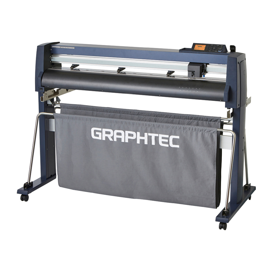
- Page 1 CUTTING PLOTTER FC9000-75/100/140/160 SERVICE MANUAL FC9000-UM-251-01-9370...
- Page 3 HISTORY OF REVISIONS No. Date issued Description of revision Page Edition 19.9.13 First Printing FC9000-UM-251-9370...
- Page 4 FC9000-UM-251-9370...
-
Page 5: Table Of Contents
CONTENTS INTRODUCTION .................1-1 Main Specifications .......................1-1 1.2 External Dimensions ......................1-2 Option & Supply Parts ......................1-3 Setup ..................2-1 Confirming the standard accessory..................2-1 2.2 Assembling the stand and basket to the Plotter ..............2-2 PARTS NAMES and FUNCTIONS ..........3-1 Parts Names and Functions .................... - Page 6 7.1.9 Replacing the Fan Cover ........................7-9 7.1.10 Replacing the Pen Block Cover ......................7-10 7.1.11 Replacing the Push Roller ........................7-11 7.1.12 Replacing the Cutting Mat ........................7-12 Internal Parts ........................7-13 7.2.1 Replacing the Rear Media Sensor .......................7-13 7.2.2 Replacing the Front Media Sensor ......................7-13 7.2.3 Replacing the Registration Mark Sensor ....................7-14 7.2.4...
- Page 7 8.2.2 When the main board was replaced (The adjustment values could not copy.) ....... 8-3 8.2.3 When the pen block was replaced ....................... 8-4 8.2.4 When the X or Y motor was replaced ....................8-4 8.2.5 When the Rear or Front X Media sensor was replaced ..............8-4 8.2.6 When the registration mark sensor was replaced ................
- Page 8 8.17 Adjusting the X Media Sensor Position ................8-45 8.17.1 Inputting the X Media Sensor Position from the recorded value ............ 8-45 8.17.2 Adjusting the X Media Sensor Position ..................... 8-48 8.18 Adjusting the 2nd Pen Exchange position ............... 8-50 8.18.1 Inputting the 2nd Pen Exchange position from the recorded value ..........
- Page 9 10 PARTS LIST ................10-1 10.1 Outer Casing.........................10-1 10.2 Control Panel ........................10-3 10.3 Pen Block ..........................10-4 10.4 Main Electrical Parts ......................10-5 10.5 Y Drive Part .......................... 10-6 10.6 Y Slider Part ......................... 10-8 10.7 X Drive Part .......................... 10-9 10.8 Stand, Basket ........................10-11 10.9 Details of Stocker Bracket ....................10-13 10.10 Details of Basket Base Bracket ..................10-14...
-
Page 10: Introduction
49 kg 56 kg 64 kg 70 kg *1 When the optional basket and Graphtec-specified media are used. *2 HP-GL is a registered trademark of Hewlett-Packard Company. *3 The RS-232C interface is option for the Japanese and Chinese model only. FC9000-UM-251-9370... -
Page 11: External Dimensions
INTRODUCTION External Dimensions Units: mm Dimensional accuracy: ±5 mm FC9000-75 FC9000-100 FC9000-140 FC9000-160 External dimensions W x D1 (D2) x H 1360×1151(803)×1232 1665×1151(803)×1232 1970×1151(803)×1232 2224×1151(803)×1232 (mm) FC9000-UM-251-9370... -
Page 12: Option & Supply Parts
INTRODUCTION Option & Supply Parts Option Option mane Model name Description Q’ty Take Up unit OPH-A43 For FC9000-140 1 set OPH-A44 For FC9000-160 1 set Flange set OPH-A52 Flange for the stock roll media 1 set Supply Parts Supply mane Model name Description Cutting blade holder... -
Page 13: Setup
Setup Setup Confirming the standard accessory When the standard accessory box is opened, confirm the following standard accessory is contained. Item Q’ty Item Q’ty Power cable 1 pc. USB cable 1 pc. 1 pc. TO ENSURE SAFE AND CORRECT 1 set USE SETUP MANUAL Cutter Blade Manual •... -
Page 14: Assembling The Stand And Basket To The Plotter
Setup Assembling the stand and basket to the Plotter Procedure (1) Take out the following part of stand from the packing box. The long parts are in the packing box of main unit. Center bar x 1 Stand side bar x 2 Foot x 2 Stopper x 2 Basket tube hanger bracket x 2... - Page 15 Setup (3) Insert the four M5L16 cap screws (long) to the thread of the center bar by hand (two on each side), and then tighten them by hand. Then fasten four M5L16 cap screws by using the Allen wrench. There is front and rear for the center bar, when instal the plotter onto stand, confirm it. Confirm this groove.
- Page 16 Setup (6) Attach a media stocker roll bracket to each of the left and right stand sides as shown in the picture below. And then fasten with the four M5L16 cap screws (two long screws for each side), using the Allen wrench.
- Page 17 Setup (9) Insert the basket tubes to the basket cloth as shown in the picture below. Insert the long tube to the center of basket cloth, and insert the short tubes to the front and rear. Long tube Short tube (10) Put on the center basket tube onto the basket tube hanger brackets, and then connect the front and rear basket tube to the basket cloth arm as shown in the picture below.
-
Page 18: Parts Names And Functions
PARTS NAMES and FUNCTIONS PARTS NAMES and FUNCTIONS Parts Names and Functions Front View Cutting groove Tool holder Cutting mat Tool carriage Cross cutter unit Pen holder (Optional) Push roller Media Set lever positioning guide Media sensor Control panel Pen station (Optional) Grit roller Power switch... - Page 19 PARTS NAMES and FUNCTIONS Rear View Media set lever USB memory port Optional RS-232C interface Push roller hold-down force switching lever for Japanese and Chinese model AC line inlet USB interface Network interface (LAN) Basket Stock rollers Stand Stopper Media stocker AC line inlet: Inlet where the power cord is connected Push roller hold-down force switching lever: Used to switch between the three pinch roller forces...
-
Page 20: Attaching A Tool
PARTS NAMES and FUNCTIONS Attaching a Tool Attach a tool (cutter pen, plotter pen) to the plotter Attaching a Tool When mounting the tool in the tool holder, push the tool all the way into the holder until its flange contacts the upper part of the holder and then tighten the screw firmly. - Page 21 PARTS NAMES and FUNCTIONS (3) Make sure that the tool bracket is engaged on the tool’s flange, and then tighten the screw. Flange Bracket to hold tool Attaching a Pen to the Two-Pen Holder (Option) The two-pen holder is a factory-installed option, and cannot be retrofitted. (1) Loosen the pen holder screw Bracker to hold tool Tool holder...
- Page 22 PARTS NAMES and FUNCTIONS (3) Make sure that the pen bracket is engaged on the pen’s flange, and then tighten the screw. Bracket to hold tool Flange Attaching a Plotting Pen to the Pen Station (1) Open the pen-hold mechanism on the pen station, and then attach a pen Holding part (2) Make sure that the bracket of the pen station is engaged in the upper groove of the pen Attach the pen with the upper groove of pen.
-
Page 23: Replacing The Cross-Cutter Blade
PARTS NAMES and FUNCTIONS Replacing the Cross-Cutter Blade Follow the procedure below to replace the cross-cutter blade that is used to cut the media after the plotting or cutting operation has been completed (1) Check that the power switch is turned off (the “O“ side is pressed down) (2) Remove the screw holding the cross-cutter blade in place, and then remove the cross-cutter blade Cross-cutter blade (3) Remove the protective cushion from the replacement cross-cutter blade Be sure to remove the... -
Page 24: Operations
OPERATIONS OPERATIONS Control Panel This section explains the function of lamps and keys on the control panel. BARCODE PAUSE/MENU PAUSE/MENU 2 key 1 key lamp ORIGIN key BARCODE COPY key ESC/CROSS CUT ENTER key Screen (LCD) 3 key 4 key SlOW key POSITION keys COND./TEST... - Page 25 OPERATIONS 1, 2, 3, 4......Select the menu number displayed in the screen. POSITION ...... There are following functions depending on the operation. Move the tool carriage and media. It will move specified distance when it is pressed once,and continuously move when it is pressed down.
-
Page 26: Reading The Screen (Lcd)
OPERATIONS Reading the Screen (LCD) Information reflecting the status will be displayed in the screen of the control panel. Name of the button and corresponding function is displayed on the screen when a function is allocated to the button on the control panel. Button name will be displayed in reverse when the button is enabled. Following items are displayed in the default screen. - Page 27 OPERATIONS Screen to set the corresponding conditions is displayed when the [PAUSE/MENU] key or [COND/TEST] key are pressed. PAUSE/MENU COND/TEST It will return to default It will return to screen when the default screen when [PAUSE/MENU] the [COND/TEST] key is key is pressed while pressed while displaying displaying MENU...
- Page 28 OPERATIONS Contents of Operation from Menu Screen MENU screen Contents of the operation and settings that is displayed in MENU screen with [PAUSE/MENU] key is as following: [1] (TOOL): ... Make the setting for the operation of the tool. [2] (ARMS): ... Make the settings and operation to position the tool and media, such as automatic scanning of the registration marks by the ARMS.
- Page 29 OPERATIONS Menu tree Default Screen Condition Setting Screen 1/3 [COND/TEST] [ENTE] [COPY] Condition Setting Screen 2/3 Condition Setting Screen 3/3 Continued FC9000-UM-251-9370...
- Page 30 OPERATIONS Default Screen (Continued) TOOLS SETTING MENU Screen Screen 1/4 [PAUSE/MENU] TOOLS SETTING Screen 2/4 TOOLS SETTING Screen 3/4 TOOLS SETTING Screen 4/4 Continued FC9000-UM-251-9370...
- Page 31 OPERATIONS Default Screen (Continued) ARMS SETTING MENU Screen Screen 1/2 [PAUSE/MENU] ARMS SETTING Screen 2/3 ARMS SETTING Screen 3/3 AREA PARAMETERS MENU Screen Screen 1/2 [PAUSE/MENU] AREA PARAMETERS Screen 2/2 Continued FC9000-UM-251-9370...
- Page 32 OPERATIONS Default Screen (Continued) MEDIA SETTING MENU Screen Screen 1/2 [PAUSE/MENU] MEDIA SETTING Screen 2/2 When the Take-UP option is installing, this menu is displayed. When the Take-UP option is installing, this menu is displayed. Continued FC9000-UM-251-9370...
- Page 33 OPERATIONS Default Screen (Continued) INTERFACE MENU Screen Screen 1/3 [PAUSE/MENU] [] INTERFACE Screen 2/3 When the RS-232C When the RS-232C option is installing, this option is installing, this menu is displayed. menu is displayed. The MAC address is displyed when the [] key is pressed in this menue.
- Page 34 OPERATIONS Default Screen (Continued) ADVANCE MENU Screen Screen 1/4 [PAUSE/MENU] [] ADVANCE Screen 2/4 ADVANCE Screen 3/4 ADVANCE Screen 4/4 Continued FC9000-UM-251-9370 4-11...
- Page 35 OPERATIONS Default Screen (Continued) TEST MENU Screen Screen 1/2 [PAUSE/MENU] [] TEST Screen 2/2 When the media is loading, the diagnostics is not able to perform. DATA LINK MENU Screen Screen 1/2 [PAUSE/MENU] [] DATA LINK Screen 2/2 FC9000-UM-251-9370 4-12...
-
Page 36: Recommended Parts List
RECOMMENDED PARTS LIST RECOMMENDED PARTS LIST Part No. Description -100 -140 -160 Remarks U792900700 Main Board, FC90, PN5122-01 U792900710 Main Board, FC90RS-232C, PN5122-01 For optional RS-232C Model U792900735 Cam Sensor Board, PN5122-06 U692180314 Flexible Cable, FFC512205D Cam sensor U792900725 Y Relay Board, PN5122-03 U692180273 Y Flexible Cable, FFC512201C –... -
Page 37: List Of Tools
LIST OF TOOLS LIST OF TOOLS Tools Adjustment Item Tool 1 Pen force adjustment Cutter Pen Holder (CB09) Colex gauge (50,300,500 gf) 2 Distance adjustment Glass scale 3 Pen block height adjustment 10 mm height block 4 Firmware update PC, USB I/F cable 5 X-drive belt tension adjustment Push-pull gauge (2 kg) 6 Y-drive belt tension adjustment... -
Page 39: Disassembly And Reassembly
DISASSEMBLY AND REASSEMBLY DISASSEMBLY AND REASSEMBLY Exterior Parts 7.1.1 Replacing the Right Side Cover How to detach the right side cover (1) Remove the four M4L6 binding head screws from the right side cover. (2) Detach the right side cover. Right side cover M4L6 binding head screw How to reinstall the right side cover... -
Page 40: Replacing The Left Side Cover
DISASSEMBLY AND REASSEMBLY 7.1.2 Replacing the Left Side Cover How to detach the left side cover (1) Remove the four M4L6 binding head screws from the left side cover. (2) Detach the left side cover. Left side cover M4L6 binding head screw How to reinstall the left side cover (1) Reattach the left cover in the reverse order in which it was detached. -
Page 41: Replacing The Control Panel Assembly
DISASSEMBLY AND REASSEMBLY 7.1.3 Replacing the Control Panel Assembly How to detach the control panel assembly (1) Detach the right side cover (Refer to subsection 7.1.1.). (2) Remove the four M3L6 binding head screws holding the control panel assembly. M3L6 binding head screw Control panel assembly (3) Disconnect the control panel flexible cables from the control panel board. -
Page 42: Replacing The Center Cover
DISASSEMBLY AND REASSEMBLY 7.1.4 Replacing the Center Cover How to detach the center cover (1) Detach the right side cover (Refer to subsection 7.1.1.). (2) Detach the control panel assembly (Refer to subsection 7.1.3.). (3) Remove the six M3L6 binding head screws holding the center cover. M3L6 binding head screw Center cover (4) Detach the center cover. -
Page 43: Replacing The Front Guide
Replacing the Front Guide How to detach the front guide (1) Remove the four M3L6 binding head screws from the front guide for the FC9000-75. (Remove the five M3L6 binding head screws from the front guide for the FC9000-100. Remove the six M3L6 binding head screws from the front guide for the FC9000-140. -
Page 44: Replacing The Rear Guide
Replacing the Rear Guide How to detach the rear guide (1) Remove the four M3L6 binding head screws from the rear guide for the FC9000-75. (Remove the five M3L6 binding head screws from the rear guide for the FC9000-100. Remove the six M3L6 binding head screws from the rear guide for the FC9000-140. -
Page 45: Replacing The Rear Writing Panel
(2) Remove the M3L6 binding head screw from the top of the rear writing panel. (3) Remove the five M3L6 binding head screws from the rear of the rear writing panel for the FC9000-75. (Remove the five M3L6 binding head screws from the rear of the rear writing panel for the FC9000-100. -
Page 46: Replacing The Front Writing Panel Assembly
(3) Detach the rear writing panel (Refer to subsection 7.1.7.). (4) Remove the ten M3L6 binding head screws holding the front writing panel assembly for the FC9000-75. (Remove the twelve M3L6 binding head screws holding the front writing panel assembly for the FC9000-100. -
Page 47: Replacing The Fan Cover
DISASSEMBLY AND REASSEMBLY 7.1.9 Replacing the Fan Cover How to detach the fan cover (1) Remove the M3L6 binding head screw holding the fan cover. (2) Detach the fan cover. Fan cover M3L6 binding head screw How to reinstall the fan cover (1) Reattach the fan cover in the reverse order in which it was detached. -
Page 48: Replacing The Pen Block Cover
DISASSEMBLY AND REASSEMBLY 7.1.10 Replacing the Pen Block Cover How to detach the pen block cover (1) Remove the two M3L6 binding head screws holding the pen block cover. Pen block cover M3L6 binding head screw (2) Detach the pen block cover. There is a hook inside of this part. -
Page 49: Replacing The Push Roller
DISASSEMBLY AND REASSEMBLY 7.1.11 Replacing the Push Roller How to detach the Push Roller (1) Pull out the push roller pin from the push roller shaft by using the needle nose pliers. Push roller pin (2) Pull out the push roller shaft from the push roller arm. Push roller arm Push roller shaft (3) Detach the push roller. -
Page 50: Replacing The Cutting Mat
DISASSEMBLY AND REASSEMBLY 7.1.12 Replacing the Cutting Mat How to detach the cutting mat (1) Peel off the cutting mat from the left side of cutting mat base. Peel off the cutting mat Cutting Mat from here. How to reinstall the cutting mat (1) Clean the cutting mat base. -
Page 51: Internal Parts
DISASSEMBLY AND REASSEMBLY Internal Parts 7.2.1 Replacing the Rear Media Sensor How to detach the rear media sensor (1) Detach the rear guide (Refer to subsection 7.1.6.). (2) Remove the M3L10 binding head screw attaching the rear media sensor. (3) Disconnect the sensor from the connector. M3L10 binding head screw Rear media sensor How to reinstall the rear media sensor... -
Page 52: Replacing The Registration Mark Sensor
DISASSEMBLY AND REASSEMBLY 7.2.3 Replacing the Registration Mark Sensor How to detach the registration mark sensor (1) Detach the pen block cover (Refer to subsection 7.1.10.). (2) Remove the M3L6 binding head screw holding the registration mark sensor unit. M3L6 binding head screw (3) Slide the registration mark sensor unit to upper direction, and then pull out it to the front side from the pen block. - Page 53 DISASSEMBLY AND REASSEMBLY (6) Remove the two M2L3 binding head screws holding the solenoid, and then detach it from the registration mark sensor unit. M2L3 binding head screw (7) Remove the two C2L5 self-tapping screws holding the registration mark sensor, and then detach it from the registration mark sensor unit.
-
Page 54: Replacing The Control Panel Board
DISASSEMBLY AND REASSEMBLY 7.2.4 Replacing the Control Panel Board How to detach the control panel board (1) Detach the control panel assembly (Refer to subsection 7.1.3.). (2) Gently lift up the lock of connector for LCD flexible cable on the control board, and then unlock the connector. -
Page 55: Replacing The Lcd
DISASSEMBLY AND REASSEMBLY 7.2.5 Replacing the LCD How to detach the control panel board ant the LCD (1) Detach the control panel assembly (Refer to subsection 7.1.3.). (2) Detach the control panel board (Refer to subsection 7.2.4.). (3) Slide the LCD to the left from the hooks, and then detach the LCD from the control panel cover. Control panel cover Hook How to reinstall the control panel board and the LCD... -
Page 56: Replacing The Pen Block
DISASSEMBLY AND REASSEMBLY 7.2.6 Replacing the Pen Block How to detach the pen block (1) Detach the right side cover (Refer to subsection 7.1.1.). (2) Detach the control panel assembly (Refer to subsection 7.1.3.). (3) Detach the center cover (Refer to subsection 7.1.4.). (4) Remove the two M3L6 binding head screws attaching the pen block cover. - Page 57 DISASSEMBLY AND REASSEMBLY (8) Remove the three M4L6 binding head screws attaching the pen block, and then detach the pen block from the Y slider. Pen block M4L6 binding head screw Regarding the spare parts of pen block The spare parts of pen block is not including the registration mark sensor and the cross cutter blade. When the pen block is replacing, remove the registration mark sensor and the cross cutter blade from the used pen block.
-
Page 58: Replacing The Y-Belt
DISASSEMBLY AND REASSEMBLY 7.2.7 Replacing the Y-belt How to detach the Y-belt (1) Detach the right side cover (Refer to subsection 7.1.1.). (2) Detach the left side cover (Refer to subsection 7.1.2.). (3) Detach the control panel assembly (Refer to subsection 7.1.3.). (4) Detach the center cover (Refer to subsection 7.1.4.). - Page 59 DISASSEMBLY AND REASSEMBLY (8) Remove the four M3L6 binding head screws attaching the right and left Y-belt stopper plates to the slider. Stopper Y belt M3L6 binding head screw (9) Detach the Y-belt from the unit. How to reinstall the Y-belt (1) Shave 2 to 3 mm off both ends of the Y-belt until the wire comes out as shown below.
- Page 60 DISASSEMBLY AND REASSEMBLY (4) There is direction for the Y-belt stopper plate, confirm it, and then attach the Y belt with the Y-belt stopper plate to the Y slider. This bulge must to inside. Y belt Y belt stopper plate Y slider (5) Attach the pen block (Refer to subsection 7.2.6.).
-
Page 61: Replacing The Push Roller Sensor Board
DISASSEMBLY AND REASSEMBLY 7.2.8 Replacing the Push Roller Sensor Board How to detach the push roller sensor board (1) Detach the control panel assembly (Refer to subsection 7.1.3.). (2) Detach the center cover (Refer to subsection 7.1.4.). (3) Detach the pen block (Refer to subsection 7.2.6.). (4) Remove the two M3L6 binding head screws attaching the push roller sensor bracket to the slider. -
Page 62: Replacing The Y-Relay Board
DISASSEMBLY AND REASSEMBLY 7.2.9 Replacing the Y-relay Board How to detach the Y-relay board (1) Detach the control panel assembly (Refer to subsection 7.1.3.). (2) Detach the center cover (Refer to subsection 7.1.4.). (3) Disconnect all the cables from the Y-relay board. M3L6 binding head screw Y relay board (4) Remove the three M3L6 binding head screws attaching the Y-relay board. -
Page 63: Replacing The Cam Sensor Board
DISASSEMBLY AND REASSEMBLY 7.2.10 Replacing the Cam Sensor board How to detach the cam sensor board (1) Detach the right side cover (Refer to subsection 7.1.1.). (2) Remove the M3L6 binding head screw holding the cam sensor board. Cam sensor board M3L6 binding head screw (3) Disconnect the flexible cable from the cam sensor board. -
Page 64: Replacing The Y-Motor
DISASSEMBLY AND REASSEMBLY 7.2.11 Replacing the Y-motor How to detach the Y-motor (1) Detach the right side cover (Refer to subsection 7.1.1.). (2) Mark the position of temperature sensor board as shown in the picture below. Mark the position of Y Motor temperature sensor Temperature sensor board... - Page 65 DISASSEMBLY AND REASSEMBLY (6) Mark the position of screws which are holding the Y motor as shown in the picture below. Mark the position of screws which are holding the Y motor. (7) Remove the three M3L6 binding head screws holding the Y-motor. (8) Detach the Y-motor.
- Page 66 DISASSEMBLY AND REASSEMBLY How to reinstall the Y-motor (1) Attach the Y-motor pulley to the Y-motor at the following position. Y motor pulley 0.5 mm Y motor (2) Attach the Y-motor to the Y-motor bracket. (3) Hang the Y-drive belt on the Y-motor pulley and the Y-drive pulley. (4) Tighten the two M3L4WP set screws that hold the Y-motor pulley.
-
Page 67: Replacing The X-Motor
DISASSEMBLY AND REASSEMBLY 7.2.12 Replacing the X-motor How to detach the X-motor (1) Detach the right side cover (Refer to subsection 7.1.1.). (2) Disconnect the X motor power cable from connecter J1010 on the main board. X Motor J1004: X motor encoder cable J1010: X motor power cable (3) Mark the position of screws which are holding the X motor as shown in the picture below. - Page 68 DISASSEMBLY AND REASSEMBLY (5) Mark the position of temperature sensor board. X Motor X motor pulley M3L4WP set screw Temperature sensor board (6) Detach the temperature sensor board which is attaching by cable tie on the X motor. (7) Loosen the two M3L4WP set screws holding the X-motor pulley, then detach the X-motor pulley. How to reinstall the X-motor (1) Attach the X-motor pulley to the X-motor at the following position.
-
Page 69: Replacing The Main Board
DISASSEMBLY AND REASSEMBLY 7.2.13 Replacing the Main Board How to detach the main board (1) Detach the right side cover (Refer to subsection 7.1.1.). (2) Disconnect all the cables and flexible cables from their connectors on the main board. (3) Remove the five M3L6 binding head screws holding the main board to the chassis. Main board M3L6 binding head screw (4) Detach the main board from the chassis. -
Page 70: Replacing The Fan
DISASSEMBLY AND REASSEMBLY 7.2.14 Replacing the Fan How to detach the vacuum fan (1) Detach the front guide (Refer to subsection 7.1.5.). (2) Disconnect the cable of vacuum fan from the fan relay cable connector. Fan relay cable connector (3) Remove the M3L6 binding head screw holding the fan cover on the bottom of plotter, and then detach it. M3L6 binding head screw Fan cover (4) Remove the two M3L35 binding head screws holding the vacuum fan as shown in the figure below. -
Page 71: Replacing The Drive Roller Shaft Assembly
DISASSEMBLY AND REASSEMBLY 7.2.15 Replacing the Drive Roller Shaft Assembly How to detach the drive roller shaft assembly (1) Detach the right side cover (Refer to subsection 7.1.1.). (2) Detach the left side cover (Refer to subsection 7.1.2.). (3) Detach the front guide (Refer to subsection 7.1.5.). (4) Detach the rear guide (Refer to subsection 7.1.6.). - Page 72 DISASSEMBLY AND REASSEMBLY (10) Remove the M3L6 binding head screws holding the bearing covers and detach the bearing covers from the pillow blocks. (Don’t loosen the M3L6 binding head screws holding the pillow blocks.) FC9000-75 FC9000-100 FC9000-140 FC9000-160 Drive roller shaft assembly...
- Page 73 How to reinstall the drive roller shaft assembly (1) Reattach in the reverse order in which it was detached. (2) When the drive roller shaft assembly is installing, confirm the position of bush as shown in the picture below. FC9000-75 FC9000-100 FC9000-140 FC9000-160...
-
Page 74: Replacing The Y Flexible Cable
DISASSEMBLY AND REASSEMBLY 7.2.16 Replacing the Y Flexible Cable How to detach the Y Flexible Cable (1) Detach the right side cover (Refer to subsection 7.1.1.). (2) Detach the control panel assembly (Refer to subsection 7.1.3.). (3) Detach the center cover (Refer to subsection 7.1.4.). (4) Release the cable ties holding the Y flexible cable. - Page 75 DISASSEMBLY AND REASSEMBLY How to reinstall the Y Flexible cable (1) Fold the Y relay board side of Y flexible cable at same position with the removed Y flexible cable. (2) Move the pen block to the left end. (3) Fit the Y-flexible cable into the Y-rail as shown below. The Y-flexible cable shouldn’t touch the left side plate.
-
Page 76: Replacing The Push Roller Assembly
DISASSEMBLY AND REASSEMBLY 7.2.17 Replacing the Push Roller assembly How to detach the Push Roller assembly (1) Detach the right side cover (Refer to subsection 7.1.1.). (2) Remove the M3L6 binding head screw holding the cam sensor board. Cam sensor board M3L6 binding head screw (3) Detach the cam sensor board. - Page 77 M3L10 binding head screw Cam shaft holder (7) Mark the position of push roller stopper as shown in the picture bellow, and then loosen the screw holding the push roller stopper. FC9000-75 FC9000-100/140/160 Stopper screw Mark the position of stopper here.
- Page 78 DISASSEMBLY AND REASSEMBLY (11) Slide the push roller assembly to the notch of Y rail, and then detach the push roller assembly from the Y rail. Push roller assembly Notch of Y rail How to reinstall the Push Roller Assembly (1) Reattach the push roller assembly in the reverse order in which it was detached.
-
Page 79: Replacing The Push Roller Base
DISASSEMBLY AND REASSEMBLY 7.2.18 Replacing the Push Roller base How to detach the Push Roller base Don’t loosen any screws on the push roller assembly. (1) Detach the push roller assembly (Refer to subsection 7.2.17.). (2) Release the spring from the push roller arm. Spring Push roller arm (3) Detach the cam from the push roller assembly. - Page 80 DISASSEMBLY AND REASSEMBLY (5) Pull out the two push roller base shafts, and then detach the push roller base as shown in the picture bellow. Presser adjusting part Push roller lever Push roller base E-ring Front spring Push roller base shaft Push roller arm How to reinstall the Push Roller base (1) Reattach the push roller base in the reverse order in which it was detached.
-
Page 81: Replacing Power Supply Board
DISASSEMBLY AND REASSEMBLY 7.2.19 Replacing Power Supply Board How to detach the power supply board (1) Detach the left side cover (Refer to subsection 7.1.2.). (2) Disconnect all cables from the power supply board. (3) Remove the four M3L6 binding head screws holding the power supply board, and then detach it. Power supply board M3L6 binding head screw How to reinstall the power supply board... -
Page 82: Belt Tension Adjustments
DISASSEMBLY AND REASSEMBLY Belt Tension Adjustments 7.3.1 Y-Belt Tension Adjustment How to adjust the Y-belt tension (1) Tighten the two adjustment screws to the marking position, which was marked when detaching the Y belt. Adjustment screw (M3L28 binding head screw) Marking position Y idler pulley FC9000-UM-251-9370... - Page 83 (2) Pull the belt 20 mm towards the center using a force gauge. Adjust the Y belt tension adjustment screws evenly until the tension reads as follows: Specification of the Belt Tension Model Force gauge reading specification FC9000-75 700 g+50 FC9000-100 700 g+50 FC9000-140...
- Page 84 DISASSEMBLY AND REASSEMBLY (3) Verify that the Y belt is centered and does not move up and down when the Y-slider is moved from left to right several times. The Y-slider belt should not move up and down more than 1.5 mm. Y belt tension adjustment screws The Y belt should not...
-
Page 85: Y-Drive Belt Tension Adjustment
DISASSEMBLY AND REASSEMBLY 7.3.2 Y-Drive Belt Tension Adjustment How to adjust the Y-Drive belt tension (1) Tighten the three screws attaching the Y motor at the marking position, which was marked when detaching the Y motor. Marking position When the adjustment position was not marked adjust the Y drive belt tension by the following procedure. -
Page 86: X-Drive Belt Tension Adjustment
DISASSEMBLY AND REASSEMBLY 7.3.3 X-Drive Belt Tension Adjustment How to adjust the X-Drive belt tension (1) Tighten the three screws attaching the X motor at the marking position, which was marked when detaching the X motor. Marking position When the adjustment position was not marked adjust the X drive belt tension by the following procedure. -
Page 87: Confirming The Cable Wiring
DISASSEMBLY AND REASSEMBLY Confirming the cable wiring When the cables were reconnecting to the connector, confirm each cables are connected correctly. Specially confirm the following cables are reconnected correctly. • The cables from the X-motor to the main board. • The cables from the Y-motor to the main board. •... - Page 88 DISASSEMBLY AND REASSEMBLY Confirming the flexible cable wiring from the cam sensor board to the main board The flexible cable has a right side and a wrong side, connect the flexible cable correctly as shown in the picture below. Cam sensor board Confirm the printed side, which is facing to the right.
- Page 89 DISASSEMBLY AND REASSEMBLY Confirming the flexible cable wiring from the control panel board to the main board The flexible cable has a right side and a wrong side, connect the flexible cable correctly as shown in the picture below. [Main board side] Control panel flexible cable Control panel flexible cable Confirm the printed side,...
- Page 90 DISASSEMBLY AND REASSEMBLY Confirming the flexible cable wiring from the push roller sensor board to the Y relay board The flexible cable has a right side and a wrong side, connect the flexible cable correctly as shown in the picture below. [Y relay board side] Push roller sensor flexible cable Confirm the printed side,...
-
Page 91: Electrical Adjustment
Electrical Adjustment Electrical Adjustment List of Items Requiring Readjustment If you replaced any of the units listed in the table below or altered their sensor positions, be sure to readjust the corresponding items. Registration Unit name Media Drive Main board sensor mark drive... -
Page 92: Flowchart Of The Adjustment Sequence
Electrical Adjustment Flowchart of the Adjustment Sequence 8.2.1 When the main board was replaced (Normal procedure) When the main board was exchanged, copy adjustment values to the main board from the NV-RAM (memory) of cam sensor board by the following procedure. Clear the NOV-RAM for corresponding model (Refer to subsection 8.7.). -
Page 93: When The Main Board Was Replaced (The Adjustment Values Could Not Copy.)
Electrical Adjustment 8.2.2 When the main board was replaced (The adjustment values could not copy.) When the main board was exchanged, if the adjustment values could not copy from the SUB-NVRAM to the main board, perform the following procedure. Clear the NOV-RAM for corresponding model (Refer to subsection 8.7.). Set the dip switch for corresponding model (Refer to subsection 8.3.). -
Page 94: When The Pen Block Was Replaced
Electrical Adjustment 8.2.3 When the pen block was replaced When the pen block was exchanged, perform the following adjustments. Adjust the pen force adjustment values (Refer to subsection 8.11.2.). Adjust the Registration Mark Sensor Sensitivity (Refer to subsection 8.14.). Adjust the Offset of Registration Mark Sensor (Refer to subsection 8.15.2.). Adjust the X Media Sensor Position (Refer to subsection 8.17.2.). -
Page 95: When The Cam Sensor Board Was Replaced
Electrical Adjustment 8.2.7 When the cam sensor board was replaced When the cam sensor board was exchanged, perform the following adjustment. Back up the adjustment value to the SUB-NVRAM (Refer to subsection 8.21.). End of adjustment 8.2.8 When the optional 2nd pen was installed When the optional 2nd pen was installed, perform the following adjustments. -
Page 96: Dip Switch Settings
Factory presets (Normal Mode) This setting depends on the model. Dip Switch (SW1) Model OFF OFF OFF OFF OFF OFF OFF OFF FC9000-75 1 2 3 4 5 6 7 8 FC9000-75 OFF OFF OFF OFF OFF OFF ON OFF... - Page 97 All adjustment values are cleared to the default value of each model when the NV-RAM CLEAR was performed. Dip Switch (SW1) Model OFF OFF OFF ON OFF OFF OFF FC9000-75 1 2 3 4 5 6 7 8 ON OFF OFF ON OFF OFF OFF FC9000-100 1 2 3 4 5 6 7 8...
-
Page 98: Explanation Of The Values Of The Main Board Settings
Electrical Adjustment Explanation of the Values of the Main Board Settings The default factory adjustment values are recorded on label in the location shown below. When the SUB-NVRAM of adjustment values are not able to copy to the main board, use this values. If you have changed any values by making adjustments, record those values for the next maintenance check. -
Page 99: Confirming The Version Of Firmware
Electrical Adjustment Confirming the version of firmware Confirm the version of firmware by the following procedure. How to confirm the version of firmware (1) Turn off the power for the FC9000 if power was turned on. (2) Turn on the power for the FC9000. (3) The firmware version is displayed while the initialization routine. (4) Confirm the firmware version. FC9000-UM-251-9370... -
Page 100: Upgrading The System Firmware
Electrical Adjustment Upgrading the System Firmware To upgrade the system firmware, prepare the following items. • Windows PC :The firmware is able to update from the Windows PC only. • USB cable • FC9000_V***_R****.X :FC9000 firmware ® • SEND.EXE :Utility to transfer files using Windows • OPS662 :USB Driver software for the FC9000 (version must later than V3.70.) Preparation (1) Copy the firmware file onto the PC. (2) Copy the SEND.EXE onto the PC. (3) Install the Windows Driver to the PC before connecting the FC9000 to the PC. - Page 101 Electrical Adjustment (6) While updating the firmware, the following menus will be displayed. (7) When the updating is completed, the plotter will start the initialization routine. The firmware version is displayed during the initialization routine. Check the firmware version that you upgraded. (8) Turn off the power. FC9000-UM-251-9370 8-11...
-
Page 102: Clearing The Nov-Ram
(2) Set SW1 to the NOV-RAM clear mode as shown below. Dip Switch (SW1) Model OFF OFF OFF ON OFF OFF OFF FC9000-75 1 2 3 4 5 6 7 8 ON OFF OFF ON OFF OFF OFF FC9000-100 1 2 3 4 5 6 7 8... - Page 103 (7) Return the SW1 setting to the normal mode as shown below. Dip Switch (SW1) Model OFF OFF OFF OFF OFF OFF OFF OFF FC9000-75 1 2 3 4 5 6 7 8 FC9000-75 OFF OFF OFF OFF OFF OFF ON OFF...
-
Page 104: Selecting Display Language & Length Unit
Electrical Adjustment Selecting Display Language & Length Unit The Language selection menu and the Length Unit selection menu are displayed at the first power on. Select the Language and the Length Unit when the Language selection is displayed. And when you are going to enter the adjustment mode select the language to English and then select the Length unit to METRIC. -
Page 105: Copying The Adjustment Value Form The Sub-Nvram
Electrical Adjustment Copying the Adjustment value form the SUB-NVRAM There is the SUB-NVRAM on the cam sensor board of FC9000. This SUB-NVRAM is memorizing all adjustment values for the FC90000. All adjustment values are able to copy to the new main board from the SUB-NVRAM of cam sensor board when the main board is replacing. -
Page 106: How To Enter The Adjustment Menu
Electrical Adjustment 8.10 How to Enter the Adjustment Menu (1) Turn on the power while pressing the SLOW and ENTER keys. After turning on the power, press the SLOW and the ENTER keys simultaneously within 2 seconds. At the ready mode, while the ENTER key is pressing, press the ORIGIN key. And then the plotter is reset. - Page 107 Electrical Adjustment Adjustment Menu List Sensor & Key test. Pen pressure adjustment. Distance adjustment. Suffix setting (Set to STD for standard model, Do not change.). Registration mark sensor sensitivity adjustment. Registration mark sensor position adjustment. Home sensor position adjustment (Do not change.). Registration mark sensor level confirmation. Dots check for the LCD. Running test for X and Y directions. Registration mark sensor hood condition (Do not change.).
-
Page 108: Adjusting The Pen Force
Electrical Adjustment 8.11 Adjusting the Pen Force This adjustment will set the pen force. Perform this procedure if adjustment values could not copy from the SUB-NVRAM when replacing the main board or if the Pen Block Assembly was replaced. If you replace the main board, use the following procedure to input the recorded adjustment values. If you replace the pen block assembly, you must measure the pen force by using the Correx Dial Tension gauge and adjust pen force to the target force with following procedure. - Page 109 Electrical Adjustment (7) Press the F2 key to display the following menu. Don’t press the F1 (AUTO with gauger), this mode is used at production line only. If the F1 key pressed, readjust the pen force by the manual adjustment. (8) Press the ENTER key to display the following menu.
-
Page 110: Adjusting The Pen Force From The Measured Force
Electrical Adjustment 8.11.2 Adjusting the pen force from the measured force Required jigs and tools • Correx Dial Tension gauges (1000 g, 500 g, 300 g, 50 g) • Cutter plunger How to adjust the pen force from the measured force (1) Put into a 0.9 mm diameters cutter blade holders to the tool holder 1. - Page 111 Electrical Adjustment (9) Press the ENTER key to display the following menu. Use the UP or DOWN position key to change the force setting. (10) The pen is lowered. Use the Correx Dial Tension gauges to measure the actual force as shown in the picture below.
- Page 112 Electrical Adjustment (24) Press the ENTER key when the measured value is within the specification range (515±15g). (25) The 618g-pen force specified pen force adjustment menu appears. The pen is lowered. Use the Correx Dial Tension gauges to measure the actual force. (26) Adjust the 618g-pen force. If the measured value is not within the specification range (618±18g), reduce or increase the D/A value to be within the specification range (618±18g). (27) Press the ENTER key when the measured value is within the specification range (618±18g). Note: When adjusting the pen force, it is important to do it quickly. Delaying the pen force adjustment changes the temperature of the actuator and causes artificially lower readings. When this happens the actual pen force may be higher than the specification. This is especially true for the upper pen force adjustment.
-
Page 113: Adjusting The Friction
When the X or Y motor was replaced, perform this adjustment. Required jigs • Prepare the following size of Cutting film. FC9000-75 and 100: (Length) 1200 mm x (Width) 762 mm (30 inch) FC9000-140 and 160: (Length) 1200 mm x (Width) 1372 mm (54 inch) If you don't have above width of cutting film, prepare at least 30 inch wider cutting film. - Page 114 Electrical Adjustment (4) Press the PAUSE/MENU key to display the following menu. (5) Press the Right Position key to display the adjustment menu shown below. (6) Press the down position key to display the following menu. (7) Press the 3 key to display the following menu. (8) Press the SLOW key to display the following menu.
-
Page 115: Adjusting The Distance Accuracy
Electrical Adjustment 8.13 Adjusting the Distance Accuracy This adjustment will set the distance and the perpendicularity accuracy. Perform this procedure if adjustment values could not copy from the SUB-NVRAM when replacing the main board. When the main board was replaced, input the recorded adjustment values. When the drive roller was replaced, adjust the distance accuracy from the measuring distance. - Page 116 Electrical Adjustment (8) Press the ENTER key to set the value, then the following menu is displayed. (9) Press the F3 key to display the following menu. UP and down allow keys changes value Slow key changes unit (10) Input the Y-axis distance adjustment value from the recorded value of Y. (11) Press the ENTER key to set the value, then the following menu is displayed.
-
Page 117: Adjusting The Distance Accuracy From The Measured Distance
Electrical Adjustment 8.13.2 Adjusting the distance accuracy from the measured distance Required jigs and tools • A3 or larger size sheet of paper • A ruler which is measured longer than 360 mm • Fiber-tip pen and plunger. How to adjust the distance accuracy from the measured distance (1) Mount a fiber tip pen to the rear tool holder. - Page 118 Electrical Adjustment (9) Press the F3 key to display the following menu. Regarding the DRAW PATTERN and the ADJUSTED PATTERN: The DRAW PATTERN writes the original pattern which is not adjusted, therefore the adjustment distance must measure from this pattern. And this pattern writes always same distance even if adjusted values are input.
- Page 119 Electrical Adjustment (14) Press the ENTER key to set the value, then the following menu is displayed. (15) Press the F3 key to display the following menu. UP and down allow keys changes value Slow key changes unit (16) Input the Y-axis distance adjustment value by the actual measuring value of Y. (If you measured the 249.0 mm for the Y-axis, input the 249.00.) (17) Press the ENTER key to set the value, then the following menu is displayed.
-
Page 120: Adjusting The Registration Mark Sensor Sensitivity
Electrical Adjustment 8.14 Adjusting the Registration Mark Sensor Sensitivity This adjustment will set the registration mark senor sensitivity. Perform this procedure if adjustment values could not copy from the SUB-NVRAM when replacing the main board. When the registration mark sensor or the main board was replaced, this adjustment must be performed. Preparation Print out the registration mark sensor sensitivity adjustment sheet which is on the last page of this chapter to A4 size white copy paper. - Page 121 Electrical Adjustment (5) Press the PAUSE/MENU key to display the following menu. (6) Press the Right position key to display the adjustment menu shown below. (7) Press the Up position key to display the following menu. (8) Press the F1 key to display the following menu. (9) Press the F2 key to display the following menu.
- Page 122 Electrical Adjustment (12) Press the ENTER key to store the setting. (13) Turn off the power to exit from the adjustment menu. (When other adjustment is going to perform continuously it does not need to turn off the power.) FC9000-UM-251-9370 8-32...
-
Page 123: Adjusting The Offset Of Registration Mark Sensor
Electrical Adjustment 8.15 Adjusting the Offset of Registration Mark Sensor This adjustment will set the offset of tool and the registration mark senor position. Perform this procedure if adjustment values could not copy from the SUB-NVRAM when replacing the main board or the registration mark sensor was replaced or detached. - Page 124 Electrical Adjustment (4) Press the Right position key to display the adjustment menu shown below. (5) Press the Up position key to display the following menu. (6) Press the F2 key to display the following menu. (7) Press the F2 key to display the following menu. UP and down allow keys changes value (8) Input the X-offset adjustment value from the recorded value of registration mark of X offset.
- Page 125 Electrical Adjustment (12) Press the ENTER key to set the Y offset, the following menu is displayed. (13) Press the ENTER key, the following menu is displayed. (14) Turn off the power to exit from the adjustment menu. (When other adjustment is going to perform continuously it does not need to turn off the power.) FC9000-UM-251-9370 8-35...
-
Page 126: Adjusting The Registration Mark Sensor Offset Position From The Measured Values
Electrical Adjustment 8.15.2 Adjusting the registration mark sensor offset position from the measured values Required jigs and tools • Target sheet • Cutter plunger and blade • A ruler Preparation • Adjust the blade length that it is not cut through the target sheet. •... - Page 127 Electrical Adjustment (7) Press the Right position key to display the adjustment menu shown below. (8) Press the Up position key to display the following menu. (9) Press the F2 key to display the following menu. (10) Press the F1 key (MANUAL) to display the following menu. (11) Press the F2 key (SCAN) to display the following menu.
- Page 128 Electrical Adjustment (13) Press the ENTER key after the tool position was moved to the above area. The plotter will scan the cross mark target, and then it will cut the cross mark target. When the offset is correct, it will cut When the offset is not correct, it will onto the cross mark target.
- Page 129 Electrical Adjustment (19) Press the ENTER key, after it is input. (20) Perform the steps from (10) to (13) to confirm the offset was adjusted correctly. (21) Press the ENTER key, the following menu is displayed. (22) Turn off the power to exit from the adjustment menu. (When other adjustment is going to perform continuously it does not need to turn off the power.) FC9000-UM-251-9370 8-39...
-
Page 130: Adjusting The Cross Cutter Home Position
Electrical Adjustment 8.16 Adjusting the Cross Cutter Home Position This adjustment will set the cross cutter home position value. Perform this procedure if adjustment values could not copy from the SUB-NVRAM when replacing the main board. When the pen block or the cross cutting mechanism parts was replaced, this adjustment must be performed. 8.16.1 Inputting the Cross Cutter Home Position from the recorded values How to input Cross Cutter Home Position from the recorded values... - Page 131 Electrical Adjustment (7) Press the F1 key to display the following menu. The pen block moves to the left side of the cross cutter home position. (8) Input the cross cutter home adjustment value from the recorded value of cross cutter home. (9) Press the ENTER key to display the following menu.
-
Page 132: Adjusting The Cross Cutter Home Position From The Measured Values
Electrical Adjustment 8.16.2 Adjusting the Cross Cutter Home Position from the measured values Preparation Detach the pen block cover to see the adjustment position when the recorded values are not used. How to adjust the cross cutter home position (1) Turn on the power while pressing the SLOW and the ENTER keys. (2) The plotter displays the following menu. - Page 133 Electrical Adjustment (8) Press the F2 key to display the following menu. (9) Press the F1 key to display the following menu. The pen block moves to the left side of the cross cutter home position. (10) Confirm the gap between the cross cutter dog and the cross cutter release plate. (11) Adjust the gap to a value in the range of 0.6 mm to 1.0 mm. Press the UP or DOWN position key to adjust the gap.
- Page 134 Electrical Adjustment (14) Press the ENTER key to store the setting, and the following menu is displayed. (15) Turn off the power to exit from the adjustment menu. (When other adjustment is going to perform continuously it does not need to turn off the power.) FC9000-UM-251-9370 8-44...
-
Page 135: Adjusting The X Media Sensor Position
Electrical Adjustment 8.17 Adjusting the X Media Sensor Position This adjustment will set the registration mark sensor position and the X media sensor position. Perform this procedure if adjustment values could not copy from the SUB-NVRAM when replacing the main board. - Page 136 Electrical Adjustment (7) Press the Down position key until the following menu is displayed. (8) Press the F3 key to display the following menu. (9) Press the F2 key to display the following menu. UP and down allow keys changes value (10) Input the front X media sensor adjustment value from the recorded.
- Page 137 Electrical Adjustment (15) Press the ENTER key to display the following menu. (16) Turn off the power for the plotter. (When other adjustment is going to perform continuously it does not need to turn off the power.) FC9000-UM-251-9370 8-47...
-
Page 138: Adjusting The X Media Sensor Position
Electrical Adjustment 8.17.2 Adjusting the X Media Sensor Position When the media sensor was replaced or detached, or when the registration mark sensor was replaced or detached, perform this adjustment. Preparation Make a adjustment target sheet as shown in the picture below. Make a 100 mm x 20 mm rectangle hole on the A4 copy paper to the following position. - Page 139 Electrical Adjustment (5) Press the PAUSE/MENU key to display the following menu. (6) Press the Right position key to display the following menu. (7) Press the Down position key until the following menu is displayed. (8) Press the F3 key to display the following menu. (9) Press the F1 key, and then the plotter scan the adjustment target sheet, and then it automatically adjust the front and the rear media sensor position with the registration mark sensor.
-
Page 140: Adjusting The 2Nd Pen Exchange Position
Electrical Adjustment 8.18 Adjusting the 2nd Pen Exchange position This adjustment will set the 2nd pen exchange position. Perform this procedure if adjustment values could not copy from the SUB-NVRAM when replacing the main board which main board adjusted for the 2nd pen option. When the main board was replaced or the 2nd Pen option was installed, perform this adjustment. - Page 141 Electrical Adjustment (7) Press F3 key to display the following menu. Input Y exchange position value using the up or the down position key. (8) Input the Y exchange position value from the recorded. (9) Press the ENTER key to display the following menu. (10) Press F4 key to display the following menu.
-
Page 142: Adjusting The 2Nd Pen Exchange Position
Preparation • Confirm the bit 7 of SW1 is ON for 2nd Pen option. This setting depends on the model. Dip Switch (SW1) Model FC9000-75 OFF OFF OFF OFF OFF OFF ON OFF 2nd pen option model 1 2 3 4 5 6 7 8 FC9000-100 ON OFF OFF OFF OFF OFF ON OFF... - Page 143 Electrical Adjustment (6) Press the Right position key to display the following menu. (7) Press the Down position key until the following menu is displayed. (8) Press the F2 key to display the following menu. (9) Press the F2 key to move the pen carriage to the exchange position. And then confirm the gap between the 2nd pen holder and the 2nd pen station.
- Page 144 Electrical Adjustment (12) Press the ENTER key when the gap became to 1.1 mm. (13) When the height is not same height, press the F4 key to adjust the height. Adjust height using the up or the down position key. (14) Mount a fiber tip pen in the 2nd pen station.
-
Page 145: Adjusting The Spacing Between Tool 1 And Tool 2
Electrical Adjustment 8.19 Adjusting the Spacing Between Tool 1 and Tool 2 This adjustment will set the spacing between tool 1 and tool 2. Perform this procedure if adjustment values could not copy from the SUB-NVRAM when replacing the main board. - Page 146 Electrical Adjustment (8) Press the ENTER key after offset value is input, the following menu is displayed. (9) Press the F4 key to display the following menu. Set the Y-offset value by using the UP or DOWN position key. (10) Input the Y-offset value from the recorded. (11) Press the ENTER key after offset value is input, the following menu is displayed.
-
Page 147: Adjusting The Spacing Between Tool 1 And Tool 2
• Confirm the bit 7 of SW1 is ON for 2nd Pen option. This setting depends on the model. Dip Switch (SW1) Model FC9000-75 OFF OFF OFF OFF OFF OFF ON OFF 2nd pen option model 1 2 3 4 5 6 7 8 FC9000-100 ON OFF OFF OFF OFF OFF ON OFF... - Page 148 Electrical Adjustment (5) Press the PAUSE/MENU key to display the following menu. (6) Press the Right Position key to display the adjustment menu shown below. (7) Install the fiber tip pens to the tool 1 holder (rear) and 2nd pen station (Right side plate of holder). (8) Press the down position key until the following menu is displayed. (9) Press the F2 key to display the following menu. (10) Set adjustment pen force to 10 for the fiber tip pens.
- Page 149 Electrical Adjustment (13) Press the F1 key to display the following menu. (14) Press the F1 key to display the following menu. (15) Press the F1 key to select the TOOL 1-2. (16) The following menu is displayed. The adjustment tool is shown 1-2. (17) Press the F2 key to display, the following menu is displayed.
- Page 150 Electrical Adjustment (19) The following menu is displayed after the cross marks plots. (20) Measure the offset between the tool 1 cross mark and the tool 2 lines. (21) When it needs to adjust for X direction (feeding direction), press the F3 key to display the following menu.
- Page 151 Electrical Adjustment complete the adjustment. (27) Press the ENTER key, the following menu is displayed. (28) Press the ENTER key, the following menu is displayed. (29) Turn off the power for the plotter. (When other adjustment is going to perform continuously it does not need to turn off the power.) FC9000-UM-251-9370 8-61...
-
Page 152: Setting The Number Of Push Rollers
Electrical Adjustment 8.20 Setting the Number of Push Rollers This will set the number of push rollers. Perform this procedure if adjustment values could not copy from the SUB-NVRAM when replacing the main board. When the main board or the optional push roller was installed, perform this adjustment. How to set the number of push rollers (1) Turn on the power while pressing the SLOW and the ENTER keys. - Page 153 Electrical Adjustment (8) Press the ENTER key after it is set, the following menu is displayed. (9) Turn off the power for the plotter. (When other adjustment is going to perform continuously it does not need to turn off the power.) FC9000-UM-251-9370 8-63...
-
Page 154: Back Up The Adjustment Value To The Sub-Nvram
Electrical Adjustment 8.21 Back up the adjustment value to the SUB-NVRAM This function will backup the adjustment values of main board to the SUB-NVRAM of the cam sensor board. Perform this procedure when the SUM-NVRAM valuers were not able to copy to the main board from the SUB-NVRAM. - Page 155 Electrical Adjustment (5) Run the SerialNumberConfig.exe, the following menu is displayed. Input serial number here. (6) Input serial number for the FC9000. (7) Press the Write button to backup the adjustment values to the Sub-NVRAM. (8) Turn off the power after the “READY” was displayed on the LCD of FC9000. (9) Turn on the power while pressing the DOWN ARROW key and the ENTER key.
- Page 156 Electrical Adjustment REGISTRATION MARK SENSOR LEVEL ADJUST LOAD MEDIA TO FC9000 (SHEET) MOVE TOOL POSITION TO CENTER OF WHITE SQUARE. FC9000-UM-251-9370 8-66...
- Page 157 Electrical Adjustment FC9000-UM-251-9370 8-67...
-
Page 158: Troubleshooting
TROUBLESHOOTING TROUBLESHOOTING The Plotter is Turned On But Doesn’t Operate Symptom Verification item Solution When turn on the power, Is the plotter being supplied with Check that the power cord is securely nothing is displayed on power? connected to the plotter’s AC line inlet. Does it occur at the first power on? When the status of plotter is waiting in the LCD panel and the... -
Page 159: Media Loading Operations
TROUBLESHOOTING Media Loading Operations Symptom Verification item Solution When the media was Is the Y flexible cable securely Confirm the Y flexible cable is connecting loaded, the pen block connected to the main board and the to the connector of Y relay board and the hits to the right side Y relay board? main board by the correct side, and then... - Page 160 TROUBLESHOOTING Symptom Verification item Solution When the media loaded Is the flexible cable of push roller Confirm the push roller flexible cable is it scans the push roller sensor securely connected to the connecting to the connector of Y relay position but it could not Y relay board and the push roller board and the push roller sensor board...
- Page 161 TROUBLESHOOTING Symptom Verification item Solution The plotter can’t Is the push roller sensor disabling? Set the pinch roller sensor enable setting recognize the Y direction in the ADVANCE menu.] of the media size, and it Set the push roller detection function to displays the maximum the enable.
-
Page 162: Cutting Operations
TROUBLESHOOTING Cutting Operations Symptom Verification item Solution The cut line is crooked. Does the blade smoothly rotate in the Replace the blade holder to new one if blade holder? the blade does not smoothly. Is the tip of blade broken? Replace the blade to new one if the tip of blade is broken. - Page 163 TROUBLESHOOTING Symptom Verification item Solution When it is cutting with The heavy roll media can not feed Set the auto pre-feed setting in the the roll media, the X from the media roll by high speed MEDIA SETTING menu. position alarm occurred. cutting.
-
Page 164: Print & Cut Operation
TROUBLESHOOTING Print & Cut Operation Symptom Verification item Solution The horizontal line of 1st When the P&C is starting, did the tool Move the tool position to the center of registration mark could position move to the center of 1st 1st registration mark. - Page 165 TROUBLESHOOTING Symptom Verification item Solution The vertical line of 2nd Is there enough margin from the right Confirm the 2nd registration mark is registration mark could push roller and the vertical line of 2nd printing in the 6 mm inside from the right not detect.
- Page 166 TROUBLESHOOTING Symptom Verification item Solution The horizontal line of 4th Was the sheet media loaded as the Confirm the 2nd and the 3rd registration registration mark could ROLL 1 or ROLL 2? mark is printing in the 6 mm inside from not detect.
- Page 167 TROUBLESHOOTING Symptom Verification item Solution The printing and cutting Was the sheet media loaded as the Confirm the 2nd and the 3rd registration positions are not fit a few ROLL 1 or ROLL 2? mark is printing in the 6 mm inside from millimeter.
-
Page 168: Usb Connection
TROUBLESHOOTING USB connection Symptom Verification item Solution The plotter is not Is not the plotter detecting with the When the plotter is connected to the PC detected by the unknown device? without installing the USB driver for the WINDOWS. plotter, it is detected as the unknown device. -
Page 169: Error Messages
TROUBLESHOOTING Error Messages 9.6.1 Hardware Error Messages Error Error Display Verification item Cause Solution code E01001 Main board is Replace the main board. defective. E01005 E01006 E01007 E01008 E01009 E01010 E01011 E01012 E01013 FC9000-UM-251-9370 9-12... - Page 170 TROUBLESHOOTING Error Error Display Verification item Cause Solution code E01014 X or Y motor is Replace the X or Y defective. motor. Or the main board is Or replace the main defective. board. E01015 E01017 Check the media. Load on the X motor Do not use heavy roll When the heavy roll was too large.
- Page 171 TROUBLESHOOTING Error Error Display Verification item Cause Solution code E01019 When this error Media is thick and Lower the cutting was displayed while hard. SPEED and/or the cutting, confirm the cutting FORCE. cutting conditions. And cut it by multi pass. Confirm there is not Movement of the Remove the obstacle.
- Page 172 TROUBLESHOOTING Error Error Display Verification item Cause Solution code E01019 Confirm the installing The cross cutter Install the cross cutter direction of cross home sensor dog is home sensor dog to cutter home dog. not installing to the the Y bar with correct Y-rail with correct direction.
- Page 173 TROUBLESHOOTING Error Error Display Verification item Cause Solution code E01028 Confirm the power The power cable Connect it securely. cable of optional of optional rewind rewind motor shaft motor shaft is not is connecting to the connecting to the connector of rewind connector of rewind motor shaft.
-
Page 174: Error Messages In Gp-Gl Command Mode
Configure your software plotter. in the command, this application menu to error is shown. permit Graphtec plotter control. When the USB cable The wrong data is Use good cable. is using, confirm too receiving by noise on long cable is not the data cable. - Page 175 Configure your software plotter. command, this error application menu to is shown. permit Graphtec plotter control. When the USB cable The wrong data is Use good cable. is using, confirm too receiving by noise on long cable is not the data cable.
- Page 176 TROUBLESHOOTING Error Error Display Verification item Cause Solution code E02005 Confirm correct The software Select the correct device is selecting configuration device. when the windows regarding the output driver is using. device has been changed. When the RS-232C The plotter’s interface Re-specify the software interface is using, conditions have been...
-
Page 177: Error Messages In Hp-Gl Emulation Mode
E03002 Confirm setting on the A command was Configure your software application software. executed with the application menu to wrong number of permit Graphtec plotter parameters. control. Re-specify the E03003 A command software application’s containing an interface conditions. unusable parameter Set the correct model was specified. - Page 178 E03011 Confirm setting on the An invalid byte was Configure your software application software. received after ESC application menu to code. permit Graphtec plotter control. Re-specify the E03012 Invalid byte was software application’s received within device interface conditions. control command.
-
Page 179: Error Messages On Arms
TROUBLESHOOTING 9.6.4 Error Messages on ARMS Error Error Display Cause Solution code E04001 Tilt to adjust with AXIS Reload the media. ALIGNMENT is too large. E04002 The adjusting distance is too Set correct distance. large. Output correct data. Incorrect data is output. E04003 Failed to adjust the AXIS or Confirm the adjusting value and the... - Page 180 TROUBLESHOOTING Error Error Display Cause Solution code E04005 When this error was displayed Do not print any printing object while scanning the horizontal around the 1st registration mark line of 1st registration mark by where it starts scanning for the Auto 1st registration mark automatic scanning.
- Page 181 TROUBLESHOOTING Error Error Display Cause Solution code E04005 When this error was displayed Print the 3rd registration mark to the while scanning the horizontal 6 mm inside from the scanning area line of 3rd registration mark (Cutting area). when sheet media was loaded There is not enough margin from with the ROLL 1 or ROLL 2.
- Page 182 TROUBLESHOOTING Error Error Display Cause Solution code E04010 This error is displayed when Create the registration mark where the data for 2nd and 3rd it is printed at the 6 mm inside from registration marks of horizontal the cutting area. lines are not in the cutting area.
- Page 183 TROUBLESHOOTING Error Error Display Cause Solution code E04014 The vertical lines of the 3rd or Load the media straightly or print the the 4th registration mark is not large size of registration marks. able to detect by tilt of media loading.
- Page 184 TROUBLESHOOTING Error Error Display Cause Solution code E04020 This error is displayed when Confirm position of registration mark the abnormal registration and the cutting data. marks are detected. E04021 This error is displayed when Check the media. Check the print the 1st registration mark position of the registration mark.
-
Page 185: Other Error Messages
TROUBLESHOOTING 9.6.5 Other Error Messages Error Error Display Cause Verification item Solution code E05001 Data size is larger Copy mode can not use. than the copy buffer Perform normal cutting size. not using the copy mode. E05002 There is no data to Perform normal cutting copy buffer. - Page 186 TROUBLESHOOTING Error Error Display Cause Verification item Solution code E05009 The barcode can not Confirm the printing Confirm the printing of detect. of barcode. barcode. Move the tool position to the barcode start mark position correctly. E05010 The rotation can not Set the rotation setting set to the barcode to OFF.
- Page 187 TROUBLESHOOTING Error Error Display Cause Verification item Solution code E05018 E05019 E05020 E05021 E05022 E05023 FC9000-UM-251-9370...
-
Page 188: Warning Messages
TROUBLESHOOTING 9.6.6 Warning Messages Error Error Display Cause Solution code W06001 Cross cut function cannot Load the roll media. operate to the sheet media. W06002 Cross cut function cannot Load the media with the rear loading operate when the media is mode. - Page 189 TROUBLESHOOTING Error Error Display Cause Solution code W06010 When it is copying the The rotation function cannot operate registration mark data, the with the registration mark function. rotation function cannot operate. W06011 When copying the registration The mirror function cannot operate mark data, the mirror function when copying the registration mark cannot operate.
-
Page 190: Service Mode
TROUBLESHOOTING Service mode 9.7.1 Sensor & Panel Switch Test Mode This mode checks status for the sensors and the switch of control panel. If there is a bad sensor or a bad switch, you can observe these symptoms by the following procedure. When the one of sensor is not working the following symptom is observed. - Page 191 TROUBLESHOOTING (5) Press the Right Position key to display the adjustment menu shown below. (6) Press the F1 key to display the menu shown below. Each short forms are corresponding to the sensors and the control panel switches as shown below. Short form Sensor or key Short form...
-
Page 192: Printing The Setting Of The Plotter
TROUBLESHOOTING 9.7.2 Printing the Setting of the Plotter Condition setting list can be printed when you need to check the current setting of the plotter. Operation (1) Set a paper larger than A3 size. (2) Set the pen tool to the tool carriage and select the condition where the pen tool is set. (3) Press the PAUSE/MENU key to display the menu below. -
Page 193: Printing The Test Pattern
TROUBLESHOOTING 9.7.3 Printing the Test Pattern Print a self-test pattern to check the operation of the plotter. Operation (1) Set a paper larger than A3 size. (2) Set the pen tool to the tool carriage and select the condition where the pen tool is set. (3) Press the PAUSE/MENU key to display the menu below. -
Page 194: Confirm The Cutting Data
TROUBLESHOOTING 9.7.4 Confirm the Cutting Data Output of the dump list of the cutting data received by the plotter is possible. It is used to check if the transmission of cutting data is performed correctly. Operation (1) Set a media larger than A4 size. (2) Set the pen tool to the tool carriage and select the condition where the pen tool is set. -
Page 195: Self Diagnostic Test
TROUBLESHOOTING 9.7.5 Self Diagnostic Test Operation status can be tested by self diagnostic test by operating the sensors and switches following the instruction on the screen. Operation (1) Confirm that the power is turned off. (2) Turn the power on without loading the media. (3) Press the PAUSE/MENU key to display the menu below. - Page 196 TROUBLESHOOTING (9) The testing items are shown below. 1 Cam lever sensor 2 Home sensor 3 Push roller sensor 4 Rear media sensor 5 Font media sensor 6 X motor signal 7 Y motor signal 8 Tool height signal 9 [1] key 10 [2] key 11 [3] key 12 [4] key...
-
Page 197: Registration Mark Sensor Test
TROUBLESHOOTING 9.7.6 Registration Mark Sensor Test This test confirms output level of registration mark sensor. When there is output from the sensor, the registration mark sensor is not defective. Preparation Print out the registration mark sensor sensitivity adjustment sheet which is on the last page of chapter 8 to A4 size white copy paper. - Page 198 TROUBLESHOOTING (5) Press the Up position key to display the following menu. (6) Press the F4 key to display the following menu. (7) Insert the registration mark sensor sensitivity adjustment sheet to under the registration mark sensor. (8) Press the F1 key to down the sensor cover. (9) Press the F4 key, servo free the pen block movement.
-
Page 199: Clear Setup Mode
TROUBLESHOOTING 9.7.7 Clear Setup Mode This mode returns all the conditions to their default settings. How to clear the setups (1) Turn on the power while pressing the UP ARROW key to display the menu shown below. (2) Press the F1 key (DEFAULT SETTING). The following menu is displayed. (3) Press the F1 key (SET DEFAULT). -
Page 200: Parts List
Remarks Rank U621804092 Right Side Cover, FC90 U621804042 Cap, Side Cover, FC90 U621804082 Left Side Cover, FC90 U621804042 Cap, Side Cover, FC90 U621804003 Center Cover, FC9000-75 FC9000-75 U621809100 Emblem, FC90-75 FC9000-75 U621814002 Center Cover, FC90-100 FC9000-100 U621819100 Emblem, FC90-100 FC9000-100... - Page 201 10 PARTS LIST Outer Casing FC9000-UM-251-9370 10-2...
-
Page 202: Control Panel
10 PARTS LIST 10.2 Control Panel Part No. Description Q’ty Remarks Rank U621804171 Control Panel Sheet, FC90 U792900780 Cover, Control Panel, FC90 621804051+621584250x4 U621804270 Key Top, Left, FC90/70 U621804250 Key Top, Cursor, FC90/70 U621804260 Key Top, Right, FC90/70 U682157130 LCD, BTG240128SFBWBGG U792900720 Control Panel Board, FC90, PN5122-02 U692180302... -
Page 203: Pen Block
10 PARTS LIST 10.3 Pen Block Part No. Description Q’ty Remarks Rank U792900745 Pen Block Assembly, FC90 U682180300 Registration Mark Sensor, KR4012-GTLF KR4012-GTLF U621803703 Holder, Registration Mark Sensor U621803722 Hood, Registration Mark Sensor U621803711 Hanger, Registration Mark Sensor U621403200 Spring, Cover Down U500052472 Solenoid, TDS-05B-DC12V U621263340... -
Page 204: Main Electrical Parts
Option for Japanese and Chinese model only. U692180314 Flexible Cable, FFC512205D Cam sensor U792900735 Cam Sensor Board, PN5122-06 U561080035 Media Sensor, PS117EL1 U682180270 Fan, 9A0924G404 FC9000-75 U682180270 Fan, 9A0924G404 FC9000-100/140/160 U792900725 Y Relay Board, PN5122-03 U692180273 Y Flexible Cable, FFC512201C FC9000-75/100 U692180293... -
Page 205: Y Drive Part
Bush, D4L3 Bush, D6L11 U621800741 Cam Shaft Holder U621803204 Bracket, Y Drive U621803211 Adjustment Plate, Y Drive Shaft Tilting U621803400 Belt, Y, 300S2M1183LW-C FC9000-75 U621813000 Belt, Y, 300S2M1488LW-C FC9000-100 U621823000 Belt, Y, 300S2M1793LW-C FC9000-140 U621833700 Belt, Y, 300S2M2047LW-C FC9000-160 U621800823... - Page 206 10 PARTS LIST Y Drive Part FC9000-UM-251-9370 10-7...
-
Page 207: Y Slider Part
10 PARTS LIST 10.6 Y Slider Part Part No. Description Q’ty Remarks Rank U792900725 Y Relay Board, PN5122-03 U692180322 Cable, FFC512206B Pinch Roller Sensor Board U792900730 Pinch Roller Sensor Board, PN5122-04 U621803550 Bracket, Pinch Roller Sensor Board U621833513 Bracket, Y Slider PCB Core, GFC-31-12 U621403322 Holder, Core... -
Page 208: Drive Part
U621802160 Roller B, L-1910ZZR P0P25LY764 FC9000-100/140 FC9000-160 FC9000-75 U621800312 Bracket, Pillow Block Cover, FC9 FC9000-100/140 FC9000-160 Bush, D10L30 FC9000-75 (STD) FC9000-100 (STD) U621352000 Push Roller FC9000-140/160 (STD) FC9000-160 (STD) FC9000-75 (STD) FC9000-100 (STD) U621803041 Shaft, Push Roller, FC9 FC9000-140/160 (STD) - Page 209 10 PARTS LIST Part No. Description Q’ty Remarks Rank FC9000-75 (STD) FC9000-100 (STD) U302200141 Spring, C-152 FC9000-140/160 (STD) FC9000-160 (STD) FC9000-75 (STD) FC9000-100 (STD) U621803074 Lever, Push Roller FC9000-140/160 (STD) FC9000-160 (STD) FC9000-75 (STD) FC9000-100 (STD) U621803114 Spring Base FC9000-140/160 (STD)
-
Page 210: Stand, Basket
10 PARTS LIST 10.8 Stand, Basket Part No. Description Q’ty Remarks Rank U621801521 Side Stay, FC9-75/100 FC9000-75/100 U621821521 Side Stay, FC9-140/160 FC9000-140/160 U621801462 Foot Assembly, FC9 U792900775 Caster, NANSIN, DNB50B M8 NANSHIN, DNB50B M8 U621801510 Cap, Foot U621801412 Center Bar, Stand FC9-75... - Page 211 10 PARTS LIST Stand, Basket FC9000-UM-251-9370 10-12...
-
Page 212: Details Of Stocker Bracket
10 PARTS LIST 10.9 Details of Stocker Bracket Part No. Description Q’ty Remarks Rank U621801311 Bracket, Right Stocker U621801721 Brake, Stocker Shaft Binding Head Screw, M3L5 Flat Washer C3 U621801730 Plate, Stocker Stopper Spacer, ARU-305S Wave Washer C5 Bush, C3L2.5 Bush, C4L2.5 Binding Head Screw, M3L6 TP Screw M4L6... -
Page 213: Details Of Basket Base Bracket
10 PARTS LIST 10.10 Details of Basket Base Bracket Part No. Description Q’ty Remarks Rank U621801771 Side Pipe, Basket U334506301 Plastic Washer, CC-0610-25 U621801930 Shaft, Side Pipe, Basket E-ring C4 U621801211 Bracket, Side Pipe, Basket Flange Cap Screw M5L10 Details of Basket Base Bracket FC9000-UM-251-9370 10-14... -
Page 214: Optional Take Up Roller (Fc9000-140/160)
10 PARTS LIST 10.11 Optional Take up roller (FC9000-140/160) Part No. Description Q’ty Remarks Rank U621828180 Take Up Roller Motor Shaft 140 FC9000-140 U621838180 Take Up Roller Motor Shaft 160 FC9000-160 U621828190 Take Up Roller Free Shaft 140 FC9000-140 U621838190 Take Up Roller Free Shaft 160 FC9000-160 U792900830... -
Page 215: Labels
Emblem, FC9000-100 U621829100 Emblem, FC9000-140 U621839100 Emblem, FC9000-160 U622658070 Label, UL_C_SEAL U622658080 Label, BLADE_CAUTION U621809130 Label, I/F Label U621809110 Model Label FC9000-75 U621819110 Model Label FC9000-100 U621829110 Model Label FC9000-140 U621839110 Model Label FC9000-160 Standard Accessories Part No. Description Q’ty Remarks... - Page 216 10 PARTS LIST FC9000-UM-251-9370 10-17...
-
Page 217: Wiring Diagrams
AC100 - 240V PN5122-01x J1001: B4P-VH J901 : 046244424010800+ J2001 : 046244424010800+ J2002 : FH12-15S-0.5SH55 1. GND 1. GND 1. GND 24. GND 15. VB- FC9000-75/100 CA512203x Brown 2. +3.3V 23. +3.3V 14. VB+ CA512205x 2. GND 69218003x 2. GND CA502200x 69218000x 3. -
Page 218: Target Electrical Component For Weee Instruction
12 Target electrical component for WEEE instruction 12 Target electrical component for WEEE instruction Material and parts that are necessary to remove on the WEEE instruction and to do separation processing The following items need to remove from the FC9000 series on the WEEE instruction. ♦... - Page 219 12 Target electrical component for WEEE instruction ♦ Electrolytic capacitors containing substances of concern (height > 25 mm, diameter > 25 mm or proportionately similar volume) No. Parts code Parts name Remarks Quantity/Unit C127 on the Switching Power Supply Unit C512 on the Switching Power Supply Unit C513 on the Switching Power Supply Unit Electrolytic capacitors C127, C512 and C513 on the Switching Power Supply Unit...
- Page 220 12 Target electrical component for WEEE instruction ♦ Unused items (parts) The following items are not used in the FC90000 series • Capacitor including polychlorinated biphenyl (PCB) • Parts including mercury such as switches and lamps for back light (for RoHs) •...
- Page 221 12 Target electrical component for WEEE instruction ♦ How to remove the electrical component of the WEEE instruction • Removing (A) Main Board (1) Remove the four M4L6 binding head screws from the right side cover. (2) Detach the right side cover. Right side cover M4L6 binding head screw (3) Disconnect all the cables and flexible cables from their connectors on the main board.
- Page 222 12 Target electrical component for WEEE instruction • Removing (B) Control Panel Board, (E) LCD (1) Remove the four M4L6 binding head screws from the right side cover. (2) Detach the right side cover. Right side cover M4L6 binding head screw (3) Remove the four M3L6 binding head screws holding the control panel assembly.
- Page 223 12 Target electrical component for WEEE instruction (4) Disconnect the control panel flexible cables from the control panel board. Control panel board Control panel flexible cable (5) Disconnect the LCD flexible cable from the control board. Control panel cover Control panel board LCD flexible cable (6) Remove the seven M2L5 self-tapping screws holding the control panel board, and then detach the control panel board from the control panel cover.
- Page 224 12 Target electrical component for WEEE instruction (7) Slide the LCD to the left from the hooks, and then detach the LCD from the control panel cover. Control panel cover Hook FC9000-UM-251-9370 12-7...
- Page 225 12 Target electrical component for WEEE instruction • Removing (C) Y Relay Board (1) Remove the four M4L6 binding head screws from the right side cover. (2) Detach the right side cover. Right side cover M4L6 binding head screw (3) Disconnect the control panel flexible cable from the main board. (4) Remove the four M3L6 binding head screws holding the control panel assembly, and then detach it.
- Page 226 12 Target electrical component for WEEE instruction (5) Remove the six M3L6 binding head screws holding the center cover. M3L6 binding head screw Center cover (6) Detach the center cover. (7) Disconnect all the cables from the Y-relay board. M3L6 binding head screw Y relay board (8) Remove the three M3L6 binding head screws attaching the Y-relay board.
- Page 227 12 Target electrical component for WEEE instruction • Removing (D) Switching Power Supply Unit (1) Remove the four M4L6 binding head screws from the left side cover. (2) Detach the left side cover. Left side cover M4L6 binding head screw (3) Disconnect all cables from the power supply board.
Need help?
Do you have a question about the FC9000-75 and is the answer not in the manual?
Questions and answers