Table of Contents
Advertisement
Quick Links
Advertisement
Table of Contents

Related Manuals for AXIOMTEK AIE800-904-FL Series


Summary of Contents for AXIOMTEK AIE800-904-FL Series
- Page 1 AIE800-904-FL Series Embedded System User’s Manual...
-
Page 2: Disclaimers
Axiomtek does not make any commitment to update the information in this manual. Axiomtek reserves the right to change or revise this document and/or product at any time without notice. No part of this document may be reproduced, stored in a retrieval system, or transmitted, in any form or by any means, electronic, mechanical, photocopying, recording, or otherwise, without the prior written permission of Axiomtek Co., Ltd. -
Page 3: Safety Precautions
Safety Precautions Before getting started, please read the following important safety precautions. The AIE800-904-FL does not come with an operating system which must be loaded first before installation of any software into the computer. Be sure to ground yourself to prevent static charge when installing any internal components. -
Page 4: Classifications
Classifications Degree of production against electric shock: not classified Degree of protection against ingress of water: IP67 Equipment not suitable for use in the presence of a flammable anesthetic mixture with air, oxygen or nitrous oxide. Mode of operation: Continuous 【Note】: All I/O connectors should be connected with corresponding cables when the system is operating with IP67 rated definition. -
Page 5: General Cleaning Tips
General Cleaning Tips Please keep the following precautions in mind while understanding the details fully before and during any cleaning of the computer and any components within. A piece of dry cloth is ideal to clean the device. Be cautious of any tiny removable components when using a vacuum cleaner to absorb dirt on the floor. -
Page 6: Scrap Computer Recycling
Scrap Computer Recycling Please inform the nearest Axiomtek distributor as soon as possible for suitable solutions in case computers require maintenance or repair; or for recycling in case computers are out of order or no longer in use. Trademarks Acknowledgments Axiomtek is a trademark of Axiomtek Co., Ltd. -
Page 7: Table Of Contents
Table of Contents Disclaimers ......................ii Safety Precautions ....................iii Classifications ....................... iv General Cleaning Tips ................... v Scrap Computer Recycling ................... vi SECTION 1 INTRODUCTION................. 1 General Descriptions ................. 1 System Specifications ............... 2 1.2.1 Product Specification ..................2 1.2.2 I/O System ...................... - Page 8 This page is intentionally left blank. viii...
-
Page 9: Section 1 Introduction
AIE800-904-FL Series User’s Manual SECTION 1 INTRODUCTION This chapter contains general information and detailed specifications of the AIE800- 904-FL. Section 1 consist of the following sub-sections: ◼ General Description ◼ System Specifications ◼ Dimensions ◼ I/O Outlets ◼ Packing List ◼... -
Page 10: System Specifications
AIE800-904-FL Series User’s Manual 5. 100 ~ 240 VAC wide range power input with 10kV surge protection 6. 1 IEEE 802.3at GbE PoE (30W) 7. Flexible I/O for customized and mission-critical projects ⚫ Reliable and Stable Design Powered by the NVIDIA® Jetson Xavier™ NX SoM, the AIE800-904-FL is equipped with M12 lockable connectors while supporting a wall mount / VESA mount kit for outdoor applications. -
Page 11: I/O System
AIE800-904-FL Series User’s Manual 1.2.2 I/O System ⚫ One C3 type HDMI for display (HDMI Full HD Resolution: up to 1920 x 1080) ® ⚫ One M12 X-Code IEEE 802.3at Gigabit PoE (30W, Intel I210-IT) ⚫ One C3 type USB 2.0 connector ⚫... -
Page 12: Dimensions
AIE800-904-FL Series User’s Manual 1.3 Dimensions The following diagrams show the dimensions and outlines of the AIE800-904-FL. 1.3.1 System Dimensions Introduction... -
Page 13: Wall-Mount Bracket Dimensions
AIE800-904-FL Series User’s Manual 1.3.2 Wall-mount Bracket Dimensions Introduction... -
Page 14: Vesa-Mount Bracket Dimensions
AIE800-904-FL Series User’s Manual 1.3.3 VESA-mount Bracket Dimensions Introduction... -
Page 15: I/O Outlets
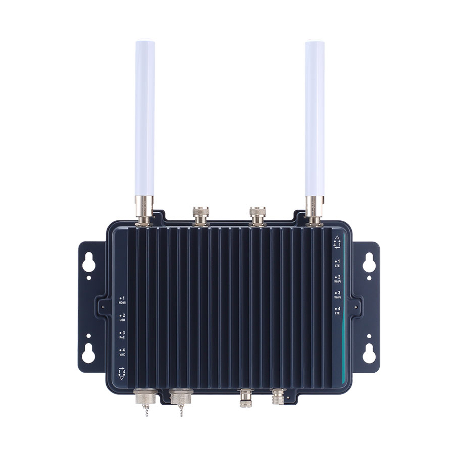
AIE800-904-FL Series User’s Manual 1.4 I/O Outlets The following figures show I/O outlets on the front of the AIE800-904-FL. Top View Bottom View Introduction... -
Page 16: Packing List
Screws pack x 1 ⚫ Thermal pad kit x 1 ※Regarding the latest product manual, please download them from Axiomtek official website. 1.6 Model List Rugged IP67-rated Fanless Edge AI System with NVIDIA® Jetson Xavier™ NX, 1 HDMI, 1 GbE PoE, 1 USB and 100 to... -
Page 17: Section 2 Hardware Installation
State Drive) and PCI Express Mini card modules. Section 2 contains guidelines for hardware installation. 【Caution】: Waterproof capability may be affected if the system is improperly disassembled. Under such circumstances Axiomtek shall not be held liable for any quality deterioration. 【Note】: Please refer to the tightening torque information below for all system screws: ... -
Page 18: Ssd Installation
AIE800-904-FL Series User’s Manual 2.1 M.2 SSD Installation Step 1 Turn off the system and unplug the power cord. Step 2 Turn the system upside down to locate and loosen the six screws at the bottom, as marked by the red circles in the figure below. Then remove the bottom cover. - Page 19 AIE800-904-FL Series User’s Manual Step 4 While holding the M.2 2242 Key B SSD card at a 30-degree angle up from the horizontal, slowly insert the golden finger into the M.2 2242 Key B slot until it is fully inserted in place. And secure the M.2 2242 Key B SSD card to the carrier by tightening up one M3*3L screw to the marked position.
-
Page 20: Installation Of Lte Mini Pcie Module
AIE800-904-FL Series User’s Manual 2.2 Installation of LTE Mini PCIe Module Step 1 Turn off the system and unplug the power cord. Step 2 Turn the system upside down to locate and loosen the six screws at the bottom, as marked by the red circles in the figure below. Then remove the bottom cover. - Page 21 AIE800-904-FL Series User’s Manual Step 5 Press the PCI Express mini card down gently, but firmly, and then secure the card to the carrier by tightening up the one M2*3L screw to the marked position. Step 6 Find the SMA cables from the adhesive backed cord clip attached to the chassis, as shown in the picture below.
- Page 22 AIE800-904-FL Series User’s Manual This page is intentionally left blank. Hardware Installation...
-
Page 23: Section 3 Jumper & Connector Settings
AIE800-904-FL Series User’s Manual SECTION 3 JUMPER & CONNECTOR SETTINGS Proper jumper settings configure the AIE800-904-FL to meet your application purpose. This section explains all jumpers and connectors as well as their default settings for onboard devices, respectively. 3.1 Jumper & Connector Location Carrier Board Top View Jumper &... - Page 24 AIE800-904-FL Series User’s Manual Carrier Board Bottom View Note: We strongly recommended that you should not modify any unmentioned jumper setting without Axiomtek FAE’s instruction. Any modification without instruction might cause damage to the system. Jumper & Connector Settings...
-
Page 25: Jumper Setting Summary
AIE800-904-FL Series User’s Manual 3.2 Jumper Setting Summary Proper jumper settings configure the AIE800-904-FL to meet your application purpose. We are herewith listing a summary table of all jumpers and default settings for onboard devices, respectively. Carrier Board: Jumper &... -
Page 26: Connectors
AIE800-904-FL Series User’s Manual 3.3 Connectors The AIE800-904-FL has one PoE, one USB, one HDMI and one 100~240 VAC connector. Please refer to pin assignments below: External Connectors Sections PoE Power Output Connector (M12 X-Code 8 pos Female) 3.3.1 USB 2.0 Connector (C3 Type 4 pos Female) 3.3.2... -
Page 27: Poe Power Output Connector (M12 X-Code 8 Pos Female)
AIE800-904-FL Series User’s Manual 3.3.1 PoE Power Output Connector (M12 X-Code 8 pos Female) This is a power connector for the internal PoE board. It complies with IEEE 802.3at standard via an internal cable connected to the LAN port on an SBC to power an external PoE device. -
Page 28: Hdmi Connector (C3 Type 19 Pos Female)
AIE800-904-FL Series User’s Manual 3.3.4 HDMI Connector (C3 Type 19 pos Female) The HDMI (High-Definition Multimedia Interface) is a compact digital interface which is capable of transmitting high-definition video and high-resolution audio over a single cable. Signal Signal HDMI DATA2+... -
Page 29: Debug Port Connector (Cn2)
AIE800-904-FL Series User’s Manual 3.3.6 Debug Port Connector (CN2) The CN2 is UART interface (UART Port0) for the debug port when developing software. Signal Signal UART2_TXD_3.3V UART2_RXD_3.3V UART0_TXD_3.3V UART0_RXD_3.3V PSIN# RESET# 3.3V M.2_LED# 3.3.7 CMOS Battery Interface (BAT1) This connector is used for CMOS battery interface. -
Page 30: Sim Card Slot (Scn2)
AIE800-904-FL Series User’s Manual PERn1 PERp1 PETn1 PETp1 38 DEVSLP* PERn0 PERp0 PETn0 PETp0 PERST# CLKREQ# 53 REFCLKN 54 PEWAKE# REFCLKP +3.3V +3.3V +3.3V 3.3.9 SIM Card Slot (SCN2) The AIE800-904-FL includes one SIM slot on the bottom side of the system for holding a SIM card. -
Page 31: Pci-Express Mini Card Connector (Scn3)
AIE800-904-FL Series User’s Manual 3.3.10 PCI-Express Mini Card Connector (SCN3) The AIE800-904-FL supports a full-size PCI-Express Mini Card slot. SCN3 is applying to either PCI-Express or USB 2.0 signal, and complies with PCI-Express Mini Card Spec. V1.2. Signal Signal +3.3V... - Page 32 AIE800-904-FL Series User’s Manual This page is intentionally left blank. Jumper & Connector Settings...
-
Page 33: Section 4 Jetpack Flash Method
AIE800-904-FL Series User’s Manual SECTION 4 JETPACK FLASH METHOD This section provides users with a detailed description of how to flash NVIDIA JetPack for AIE800-904-FL. Users can follow the instructions below to install or reinstall JetPack by themselves. FLASH METHOD: Please prepare a Linux host system running x86_64 Ubuntu v16.04 or 18.04... - Page 34 AIE800-904-FL Series User’s Manual Step 2. Please contact our sales or FAE for the latest JetPack. Untar the files and assemble the root file system with the command below: sudo tar xpf imagefilename 【Note】: Please type your full image name instead of imagefilename Step 3.
Need help?
Do you have a question about the AIE800-904-FL Series and is the answer not in the manual?
Questions and answers