Table of Contents
Advertisement
Quick Links
Tuner Genius XL
User Guide
(Preliminary)
Tuner Genius XL Firmware Version 0.9.12
Tuner Genius XL Windows Utility Version 0.9.12
7 June 2021
Copyright 2021 FlexRadio Systems. All Rights Reserved.
FlexRadio is a registered trademark and SmartSDR is a trademark of FlexRadio.
All other brands or names are trademarks of their respective owners.
Advertisement
Table of Contents

Related Manuals for FlexRadio Systems Tuner Genius XL

Summary of Contents for FlexRadio Systems Tuner Genius XL
- Page 1 (Preliminary) Tuner Genius XL Firmware Version 0.9.12 Tuner Genius XL Windows Utility Version 0.9.12 7 June 2021 Copyright 2021 FlexRadio Systems. All Rights Reserved. FlexRadio is a registered trademark and SmartSDR is a trademark of FlexRadio.
-
Page 2: Table Of Contents
Contents Important Notice .......................... 5 Product Description ......................... 7 What is an Antenna Tuner? ...................... 7 Circuit Description ........................... 7 Tune ............................ 8 Transmit ............................ 8 Receive ............................. 8 Features of the Tuner Genius XL ...................... 8 Front Panel .......................... ... - Page 3 Changing Modes ........................ 4 7 7.1.1 Bypass and Operate Modes ..................... 4 7 7.1.2 Standby Mode ......................... 4 7 7.1.3 Receiving ......................... 4 8 Tuning ............................. 4 8 What is a successful match? .................... 4 8 7.3.1 Automatic Tuning ...................... 4 9 7.3.2 Manual Tuning ...
- Page 4 FCC Statement .......................... 6 6 Appendix ............................ 6 7 14.1 Installing the Tuner Genius XL Windows Utility .............. 6 7 14.2 Connection Information and Pin Out Diagrams .............. 6 9 14.2.1 Power Connector ...................... 6 9 14.2.2 Ground Connection ...................... 6 9 ...
-
Page 5: Important Notice
1 Important Notice WARNING! This Radio Frequency (RF) antenna tuner is designed to operate on frequencies designated for amateur radio service. You are required to have a valid amateur radio license to transmit on these frequencies. Please operate this RF tuner only by following the quick start guide's instructions and this user guide. The unit must only be opened or serviced by a qualified technician. RF energy from transmitters can interact with some electronic devices, such as cardiac pacemakers and defibrillators. Please refer to the pacemaker or defibrillator manufacturer's instructions concerning the precautions to be taken near an amateur radio transmitter. If any interaction or interference with a pacemaker or defibrillator is suspected, STOP transmitting immediately. ! ‐ WARNING! ▲‐ Caution i – Information ! – This unit is not designed for use outdoors or in indoor environments that exceed the designed environmental limits. ! – This unit is NOT A TOY. It must not be handled by children nor placed/operated within reach of children. ! – Do not leave packing material for this unit unattended. It may be harmful to children if misused. ! – This unit contains small parts that could be a choking hazard to small children. Do not leave accessories unattended. ... - Page 6 your national law to provide any necessary isolation or protection required concerning human exposure. ▲‐ This unit must only be opened and serviced by a qualified technician. Opening the unit may void the manufacturer's warranty. ▲‐ Do not operate this unit in areas of extreme humidity. ▲‐ Avoid operating this tuner in direct sunlight or other areas of extreme heat, excessive vibration, or mechanical force. ▲‐ If this unit is intended for use in ICAS commercial applications, special safety regulations and cautions may apply to prevent accidents. ▲‐ If any defect, abnormal result, or other observations occur that are not covered by this User Guide, immediately cease operation and contact FlexRadio Support or local distributor for operational advice or repair of the unit. i – No physical modification of this tuner is allowed. Any other use or modification (including software changes that affect operational characteristics) will void the manufacturer's warranty. i – Ensure proper ventilation around the tuner; This includes 30 cm (12 inches) clearance in front and back. i – The Tuner Genius XL should be located at least 1 meter (3 feet) from any device that transmits 2.4GHz Wifi. i – Please study the complete User Guide. This document contains important information regarding the safe operation of this unit. If you have any questions, please contact the manufacturer or local distributor for details. Page 6 of 72 Copyright 2021 FlexRadio. All Rights Reserved. 7 June 2021(FW:0.9.12, Utility: 0.9.12)
-
Page 7: Product Description
2 Product Description The Tuner Genius XL™ (TGXL™) is a 2000W automatic antenna tuner with full frequency coverage from 1.8 MHz to 54 MHz. It is designed to match an antenna system with an SWR of up to 10:1 automatically. The tuner is built to "broadcast industry" commercial standards with a 1500W 100% Intermittent Commercial and Amateur Service (ICAS) power rating. The absolute maximum peal power handling capability is 2000W. All Tuner Genius XL functions are controlled either from the front panel of the tuner or from a Windows computer software application. Using the Windows application allows the TGXL to be installed away from your operating position or in another geographic location over the Internet. Additionally, high‐precision peak responding RF power and SWR meter displays are provided, eliminating the need for a separate Power/SWR meter device in your shack. The Tuner Genius XL is tightly integrated with the Power Genius XL™ (PGXL™) RF amplifier and all FLEX‐6000™ series HF transceivers. Integration is achieved using a standard LAN‐based API and communications protocol. The API is published so you can write software applications for your tuner. The Tuner Genius XL is compatible with any modern HF radio on the market today. When used in conjunction with a Power Genius XL and a FLEX‐6600 or FLEX‐6700 transceiver, you have a competitive, fully functional SO2R (single operator, two‐radio) radiosport station. In addition, support for SmartLink and multiFLEX™ operation provides frustration‐free multi‐client remote operation. 3 What is an Antenna Tuner? An antenna tuner is a device in the RF signal path between the transmitter (or transmitter + amplifier) and its antenna to improve power transfer between them by transforming the impedance presented at the transmitter's antenna feed output to a compatible value. This impedance change protects the transmitter from the potentially damaging effects of high reflected power, allowing the transmitter to avoid reducing (folding back) power to protect itself. An antenna tuner is especially useful when the antenna and feedline impedance is unknown and complex. It's important to understand that the tuner does not change the actual SWR of the antenna and feedline. Instead, it transforms the impedance presented to the transmitter. 4 Circuit Description Page 7 of 72 Copyright 2021 FlexRadio. All Rights Reserved. 7 June 2021(FW:0.9.12, Utility: 0.9.12) -
Page 8: Tune
(16,581,375) possible matching combinations. 4.1 Tune When instructed by the operator, the microcontroller keys the transmitter and executes an algorithm that quickly varies the value for each element of the matching network. For each value, the output of a directional coupler is sampled and used to search for a target impedance match. Once a match solution is found, the frequency and data necessary to recall the matching network's element values are stored in a non‐volatile memory location. When the operator next transmits on a frequency within 10kHz of a stored solution, the values required to reconstitute the pi network element values are recalled and applied to the circuit. 4.2 Transmit The microcontroller samples the directional coupler to present accurate forward power and calculated SWR during transmissions. 4.3 Receive During receive, the tuner can optionally bypass the tuned matching circuit. 5 Features of the Tuner Genius XL Input Power +12 to +20VDC (XXXma) Antenna Switching options: SO2R (70dB input isolation) 1x3 Matrix Control: Windows application RF Power: 1500W ICAS with headroom for 2000W (all modes) Tuning: Fully automatic and manual Over 16.5 million possible solutions using C‐L‐C (Pi) matching circuit First time solution time (2 to 12 seconds) – solution stored in memory Next time solution time < 20ms – solution recalled from memory 20 to 200W input power required during tuning (20W recommended) ... -
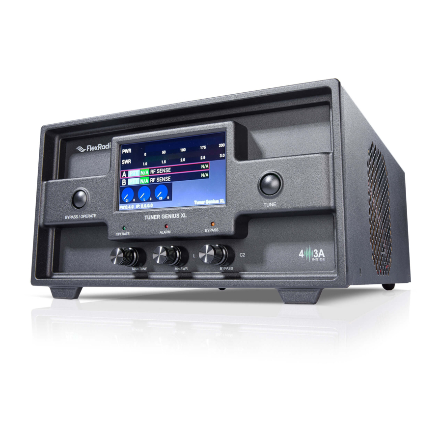
Page 9: Front Panel
Exciter Band Data Interfaces: Ethernet (includes PTT) for FlexRadio Systems transceivers CAT via RS‐232 CI‐V BCD Pin‐to‐Band (PTB) Legacy Exciter Interface Built‐in frequency counter PTT (In and Out) Open drain (XXV and XXXma maximum) Alarms Frequency out of range Wrong Band High Power SWR > 10:1 Warnings Low drive PTT Unkey Messages Manual Tuning Tuning Saved Memory Cleared Config Reset 5.1 Front Panel Designed to be easy to use and intuitive, the front panel consists of nine elements: Figure 5-1 Tuner Genius Front Panel Page 9 of 72 Copyright 2021 FlexRadio. All Rights Reserved. 7 June 2021(FW:0.9.12, Utility: 0.9.12) - Page 10 Figure 5-2 Tuner Genius Front Panel Drawing 1 Bypass/Operate button 2 Tune Button 3 4.5” (110mm) Color LCD Touchscreen Display 4 Manual Tune / C1 Adjust 5 Minimum SWR / L Adjust 6 Bypass / C2 Adjust 7 Operate LED 8 Alarm LED 9 Bypass LED Page 10 of 72 Copyright 2021 FlexRadio. All Rights Reserved. 7 June 2021(FW:0.9.12, Utility: 0.9.12)
-
Page 11: Back Panel
5.2 Back Panel Two back panel options are available. 5.2.1 1x3 Antenna Switching Option The 1x3 back‐panel option provides one input and three switchable antenna output connections. The tuner will tune the signal on the input (TX) to the currently selected output (ANT 1, 2, and 3). Only the port A connections are active, and the tuner can be controlled only by a single radio. Figure 5-3 1x3 Antenna Switching Option Page 11 of 72 Copyright 2021 FlexRadio. All Rights Reserved. 7 June 2021(FW:0.9.12, Utility: 0.9.12) -
Page 12: So2R Antenna Switching Option
Figure 5-4 1x3 Switching Option Drawing 1a PTT Output: Opto‐isolated female RCA connector. The center pin is grounded when section A of the tuner is keyed and ready to accept RF drive. 2a PTT Input: Opto‐isolated female RCA connector. Ground the center pin to shield to engage PTT for the tuner. 3a CI‐V Input A: Opto‐isolated 3.5mm female connector for Icom radio A band data 4a CAT Input A: Opto‐isolated male DB9 connector for radio A CAT command input 5a BCD/PTB Input A: Opto‐isolated DE‐15 female connector for radio A band data 6 Ethernet connection: RJ45 Local Area Network Ethernet connection 7 DC Power input: Nominally 15 volts DC, center pin positive 8 Main Power Switch 9 Station Ground B B inputs: B inputs and output are intended for the SO2R switching option and are disabled for the 1x3 switching option. 5.2.2 SO2R Antenna Switching Option The SO2R back‐panel option provides specialized support for SO2R (single operator, two radio) radiosport ... - Page 13 Separate A and B keying inputs (Push‐To‐Talk, PTT) and band data inputs are provided. At any point in time, either of the A or B sections can be keyed, but they cannot be keyed simultaneously. Figure 5-5 SO2R Switching Option Figure 5-6 SO2R Switching Option Drawing Page 13 of 72 Copyright 2021 FlexRadio. All Rights Reserved. 7 June 2021(FW:0.9.12, Utility: 0.9.12)
- Page 14 Port A RF Input: From transmitter Port A RF Output: To Antenna OUT Port B RF Input: From transmitter Port B RF Output: To Antenna PTT Output: Opto‐isolated female RCA connector. The center pin is grounded when the A or B section of the tuner is keyed and ready to accept RF drive. PTT Input: Opto‐isolated female RCA connector. Ground the center pin to shield to engage PTT for the A or B section of the tuner. CI‐V Input: Opto‐isolated 3.5mm female connector for Icom radio band data CAT Input: Opto‐isolated male DB9 connector for radio CAT command input Band Data In: Pin‐to‐Band or BCD 6 Ethernet connection: RJ45 Local Area Network Ethernet connection 7 DC Power input: Nominally 15 volts DC, center pin positive 8 Main Power Switch 9 Station Ground Page 14 of 72 Copyright 2021 FlexRadio. All Rights Reserved. 7 June 2021(FW:0.9.12, Utility: 0.9.12)
-
Page 15: Tuner Genius Xl Setup, Configuration, And Testing
6 Tuner Genius XL Setup, Configuration, and Testing 6.1 Unpacking and Setup The following accessories and materials are included with your Tuner Genius XL tuner. Carefully remove the tuner from its shipping container, unpack, and identify the items listed below: One (1) Tuner Genius One (1) 2m (6 ft) DC power cord with connector and pigtails One (1) 2m (6 ft) Ethernet cable One (1) Tuner Genius XL Quick Start Guide In addition to the above, the following are required for the initial setup of the tuner: HF or 6‐meter transceiver and antenna system Suitable coax jumper cables for interconnection of the transceiver and tuner Windows™ PC with an ethernet connection, connected to a local area network (LAN). Place your Tuner Genius XL on a flat, stable surface. Ensure the tuner has at least 30cm (12 inches) of open space in front and back to ensure adequate cooling. Then, follow these steps and refer to the following diagrams to connect your Tuner Genius XL. For connections to non‐FlexRadio products, please see section 6.3, Advanced Configuration. 6.1.1 1x3 Switch Model Connect the transceiver antenna output to the Port A TX socket on the tuner with a suitable 50‐ohm ... - Page 16 Figure 6-1 Basic 1x3 Connection Diagram The typical wiring configuration for the 1x3 tuner is shown in the diagram above. The wiring for the SO2R tuner and using the tuner with the Power Genius XL is similar and depicted below. Figure 6-2 Basic SO2R Connection Diagram Page 16 of 72 Copyright 2021 FlexRadio. All Rights Reserved. 7 June 2021(FW:0.9.12, Utility: 0.9.12)
- Page 17 Figure 6-3 SO2R Plus PGXL Connection Diagram Page 17 of 72 Copyright 2021 FlexRadio. All Rights Reserved. 7 June 2021(FW:0.9.12, Utility: 0.9.12)
- Page 18 During power‐up, the display will briefly show a splash screen like the following: Figure 6-4 Front Panel Splash Screen After the start‐up sequence, the tuner will query your local area network DHCP service for an available IP address and automatically configure the network settings. If a DHCP service is not available or does not respond, the tuner will self‐assign a Link‐Local IP Address following the RFC‐3927 specification. i – If the displayed IP Address begins with 169.254, the tuner self‐assigned a Link‐Local IP Address. Depending on your Local Area Network (LAN) configuration, this may indicate a network problem and prevent further setup. Contact FlexRadio Support for assistance. When the start‐up sequence completes and resolves an IP address, the tuner will enter Operate mode and announce its presence on your Local Area Network. The firmware version and IP address are displayed at the bottom of the screen. Initial Operating Mode Page 18 of 72 Copyright 2021 FlexRadio. All Rights Reserved. 7 June 2021(FW:0.9.12, Utility: 0.9.12)
-
Page 19: Basic Configuration
6.2 Basic Configuration Please complete the following steps to configure your Tuner Genius XL for use. 6.2.1 Connecting the Tuner Genius XL Windows Utility program The Tuner Genius XL must be configured to work with the transceiver or transceivers that will drive it. The basic configuration of the tuner is accomplished using the Tuner Genius XL Windows Utility program. Please see section 14.1, Installing the Tuner Genius XL Windows Utility, for installation instructions. Start the Tuner Genius XL Windows Utility program. It will automatically discover your Tuner Genius XL tuner, and you should see something like this: If you do not see your Tuner Genius XL in the Local devices list, please: Double‐check your network connections and cables. Ensure the Tuner Genius XL is powered on and an IP address is displayed on the front panel. Check that the PC's firewall is configured to allow the Tuner Genius XL Windows Utility to communicate over your network. The firewall is usually configured during the utility installation process. Check that your PC and Tuner Genius XL share the same logical network. For example, the IP address of your PC and the Tuner Genius XL should be similar, although not identical. If you still have trouble, please submit a HelpDesk ticket for assistance. Click on your tuner to select it, then click the Connect button. Page 19 of 72 Copyright 2021 FlexRadio. All Rights Reserved. - Page 20 You may briefly see the utility indicate it is connecting to the TGXL. Once connected, a tuner status screen will appear, like the image below. Next, click on the configuration settings button (outlined in red) to open the tuner's configuration settings, then continue to the next section of this document to set the tuner's basic configuration. Page 20 of 72 Copyright 2021 FlexRadio. All Rights Reserved. 7 June 2021(FW:0.9.12, Utility: 0.9.12)
-
Page 21: Network Tab: Set A Custom Device Name
6.2.2 Network Tab: Set a Custom Device Name You can customize your Tuner Genius XL by configuring a device name to identify your tuner. This name will appear on the tuner's front panel, in the utility's Available devices list, and the utility's main window. Select the Network Tab on the Configuration screen. Enter an appropriate name in the Device name field. Click Save i – The tuner will reset when Save is clicked. i – You do not need to click Save after every configuration change. You can postpone it until you have completed all the configuration steps, but you must click Save at some point to save the configuration for later use. Page 21 of 72 Copyright 2021 FlexRadio. All Rights Reserved. 7 June 2021(FW:0.9.12, Utility: 0.9.12) -
Page 22: Network Tab: Configuring The Network
6.2.3 Network Tab: Configuring the Network The Tuner Genius XL is configured at the factory (or after a factory reset) to use DHCP IP addressing and will automatically secure an IP Address appropriate for your network when it starts. This configuration should be sufficient for most situations. You can use the Network tab to assign a static IP Address, a static Network Mask, and a Gateway address. Static IP addresses are desirable in some network configurations but require specific technical knowledge of the network. Most configurations will not require these steps. If you don't need any of these options, please proceed to the next section. The network settings screen performs basic validation of the network settings. Note the red X next to an incorrectly formatted subnet mask below. If you are not familiar with the rules of setting or using static IP addresses but believe you need to configure one, please submit a HelpDesk ticket for assistance. When you have completed the network configuration, click Save to instruct the Tuner Genius XL to save the configuration before performing the next step. i – The tuner will reset when Save is pressed. i – It is unnecessary to exit and restart the Tuner Genius XL Windows Utility after Save is pressed. Page 22 of 72 Copyright 2021 FlexRadio. All Rights Reserved. 7 June 2021(FW:0.9.12, Utility: 0.9.12) - Page 23 i – If incorrect network information was saved, please follow the instructions in section 10, Factory Reset the Tuner Genius XL. Once you have pressed save, the configuration dialog will close, and the Tuner Genius XL Windows Utility will wait for the tuner to reset. The utility will reconnect to the tuner when it appears on the network. Before moving to the next step, please click the configuration (gear) icon then select the "Device settings" menu item. Page 23 of 72 Copyright 2021 FlexRadio. All Rights Reserved. 7 June 2021(FW:0.9.12, Utility: 0.9.12)
-
Page 24: Flexradio Tab: Configuring For A Flex-6000 Series Transceiver
6.2.4 FlexRadio Tab: Configuring for a FLEX-6000 Series Transceiver. To pair the tuner for use with a FLEX‐6000 Series transceiver, turn the radio on, then click on the FlexRadio tab in the Tuner Genius XL Configuration screen. Make sure to check the Enabled box, then follow the instructions below: Select the discovered radio S/N Location of the radio S/N Serial Number: The utility program will detect your FLEX‐6000 transceiver(s) automatically. If your radio is connected to Port A of the tuner, click on the Port A serial number drop‐down list, and select your radio. You can find your radio's serial number on a sticker on the back panel of the radio or in the Smart SDR Radio Setup dialog as shown above. If a FLEX‐6000 transceiver is connected to Port B, make the Port B configuration settings similarly. It is not required that you connect ANT1 output on a FLEX‐6000 series connect to Port A input on the tuner. Any FLEX‐6000 antenna output can be connected to any TGXL Port. However, it is required that the configuration match the physical connections. TX Antenna: This field configures the tuner to follow frequency changes in the radio on the selected antenna. The tuning solution for the indicated frequency is automatically switched in. For example, if ANT1 on a FLEX‐ 6000 transceiver is connected to tuner Port A input, select ANT1 as the value for the Port A Configuration section. When ANT1 is selected for transmitting on a slice, the tuner will make the corresponding changes to its tuning solution. The selected band will appear on the tuner's front panel and the utility screen. ANT1 is Connected to Port A, LAN PTT ANT2 is Connected to Port A, LAN PTT Page 24 of 72 Copyright 2021 FlexRadio. All Rights Reserved. 7 June 2021(FW:0.9.12, Utility: 0.9.12) - Page 25 When driven by a FLEX‐6000 Series transceiver, the tuner can be keyed over the radio's LAN connection, which automatically manages all transmit delays and other details. This option is strongly recommended. However, you can use a PTT signal wire connected to the appropriate RCA PTT Input on the tuner back panel. Wired PTT connections require a twenty millisecond (20ms) TX delay in each Transmit profile that uses the Tuner Genius XL. Select the desired keying source in the PTT Source box on the configuration screen for each radio. When the same FLEX‐6000 transceiver is connected to both Tuner Genius XL ports (A and B), you must select the same serial number for both Port A and B sections on the configuration screen. This configuration enables advanced Single Operator Two Radio (SO2R) operations using a single transceiver and tuner. SO2R Configuration ANT2‐>Port A, ANT1‐>Port B 1x3 pairing with the ANT1 output on a 6600M Click the Save button to record the configuration in the tuner. The Tuner Genius XL tuner is now configured for use by the FLEX‐6000 Series transceiver. Please proceed to section 6.5, Testing. ! – Do not connect another transceiver via RS‐232 (CAT), CI‐V, or BCD to the same tuner Port configured for a FlexRadio transceiver. i – Do not connect a PTT line when interfacing with a FLEX‐6000 transceiver. Unless some advanced need requires a separate PTT signaling wire, LAN signaling is all you need. i – The LAN integration of the Tuner Genius XL tuner is supported in SmartSDR Version 2.0 and later versions. It is not supported in SmartSDR Version 1. i – The tuner will reset when save is pressed. Page 25 of 72 Copyright 2021 FlexRadio. All Rights Reserved. 7 June 2021(FW:0.9.12, Utility: 0.9.12)
-
Page 26: Advanced Configuration
6.3 Advanced Configuration 6.3.1 Required RF Output Delay (TX Delay) The Tuner Genius XL firmware manages all tuner state transitions. However, the Operate to Transmit transition requires that the exciter slightly delay emitting RF until the transition is complete. Therefore, the Tuner Genius XL requires a minimum delay of 20 milliseconds (20ms) between the time the keying signal arrives at the tuner and the arrival of the exciter RF signal. This time delay is necessary for the tuner to complete all preparations to accept a signal safely. The following sections provide detailed information about setting the delay. 6.3.1.1 FLEX 6000-Series When keying the tuner with FLEX 6000 Series transceivers using LAN keying, a [TX Delay] value should be set to a minimum of 20 milliseconds to allow the tuner to select the correct tuning solution. i – A best practice is to create a Tuner Genius XL TX Profile for your FLEX‐6000 Series transceiver and load that when using the Tuner Genius XL. 6.3.1.2 TX Delay for Other Exciters When keying the tuner with other than FLEX 6000 Series transceivers, you will need to use a radio configuration or setting to delay RF generation by at least twenty milliseconds (20ms) after the keying signal (PTT) is sent to the tuner by the exciter. Please consult the manual for your transceiver or exciter to enable and configure the transmit delay. 6.3.1.3 Exciters Without a TX Delay Adjustment If the exciter does not support a transmit delay, then configure the tuner and exciter in the following way: ... - Page 27 Connect the tuner's PTT Output (port A or B) to the exciter in place of the keying device. When the tuner is keyed, the Tuner Genius XL will manage the output keying signal delay and assert PTT at the transceiver when the tuner is ready to accept RF. Example: Footswitch PTT wiring for a transceiver connected to Port A that does not have a TX Delay adjustment. 6.3.1.4 Band Data and Frequency Measurement based restrictions In the following sections we describe methods for supplying the tuner with band data information from exciters. When the data arrives at the tuner over a CAT connection, the frequency is provided to the tuner and the tuner records the tuning solution associated with the frequency. Up to 20 solutions, keyed by frequency can be stored for each band. When the exciter does not provide data via a CAT connection but does provide band information via a BCD or Pin2Band connection, the tuner finds a tuning solution on the exciter's frequency then stores that solution for the entire band. Only one solution is stored per band. Significant changes in frequency within a band may require re‐tuning. This also applies to Frequency Measurement configurations. If the tuner has no band data input, but senses the RF frequency, it will store one solution per band. Page 27 of 72 Copyright 2021 FlexRadio. All Rights Reserved. 7 June 2021(FW:0.9.12, Utility: 0.9.12)
-
Page 28: Interfacing With Other Exciters
6.3.2 Interfacing with Other Exciters You can connect more than one radio type to a Tuner Genius XL, provided each radio is exclusively connected to one of the tuner ports (A or B). Though each port has multiple interfaces to receive band data and key the tuner, it does not support multiple radios on a single tuner port. 6.3.2.1 Elecraft The tuner requires both band data and a PTT line from Elecraft radios. Band data is available using a custom wired BCD band decoder cable. PTT Connect an appropriate cable (RCA male terminated on both ends) between the radio's Key output and the PTT Input corresponding to the tuner Port used (A or B). Band Data (BCD) See the pinout diagram below for the cable configuration. The connection is the same for all Elecraft radio models. Page 28 of 72 Copyright 2021 FlexRadio. All Rights Reserved. 7 June 2021(FW:0.9.12, Utility: 0.9.12) - Page 29 Figure 6-5 SO2R Elecraft K3 to TGXL Diagram You can connect either the BCD/PTB Input A or BCD/PTB Input B connector on your tuner to the ACC connector on the Elecraft transceiver using a female‐to‐female DE‐15 cable (DE‐15 male connectors on both ends of the cable), customized as detailed above. Configuration To configure the tuner, click on the CAT/C‐IV tab in the Tuner Genius XL Configuration screen, and check the Enable checkbox for the appropriate port. Select the Kenwood CAT protocol the Radio type drop‐down menu for the tuner port (Kenwood CAT protocol is effectively a generic protocol supported by many makes of transceivers). Next, select the serial communication port speed and configuration parameters that apply to your radio. Finally, click the Save button to record the configuration in the tuner. i – The tuner will reset when save is pressed. Please proceed to section 6.5, Testing. Page 29 of 72 Copyright 2021 FlexRadio. All Rights Reserved. 7 June 2021(FW:0.9.12, Utility: 0.9.12)
- Page 30 6.3.2.2 Kenwood The tuner requires both band data and a PTT line from Kenwood radios. Band data is available using the CAT protocol via RS‐232. PTT Connect an appropriate cable between the radio's PTT output and the PTT Input corresponding to the tuner Port (A or B). Some models may require a custom cable to access radio PTT from an accessory connector. Please consult your manual for the correct PTT output. Multi‐band radios may have more than one, based on the band you are operating. Below is an example using the REMOTE connector on a TS‐2000. In this case, [pins 2 and 4] would be connected to the tuner's PTT IN on PORT A or PORT B. Band Data (CAT) RS‐232 (CAT) connections use a straight‐through female‐to‐female DB9 cable. Connect either the CAT Input A or CAT Input B connector on your Tuner Genius XL to the CAT connector on the Kenwood transceiver using a female‐to‐female DB9 cable. Page 30 of 72 Copyright 2021 FlexRadio. All Rights Reserved. 7 June 2021(FW:0.9.12, Utility: 0.9.12)
- Page 31 Configuration To configure the tuner, click on the CAT/C‐IV tab in the Tuner Genius XL Configuration screen. Select "Kenwood" from the Radio type drop‐down menu for the tuner port where the radio is connected. Next, select the serial communication port speed and configuration parameters that apply to your radio. Finally, click the Save button to record the configuration in the tuner. i – The tuner will reset when save is pressed. Please proceed to section 6.5, Testing. Page 31 of 72 Copyright 2021 FlexRadio. All Rights Reserved. 7 June 2021(FW:0.9.12, Utility: 0.9.12)
- Page 32 6.3.2.3 ICOM The tuner requires both band data and a PTT line from Icom radios. Band data is available using RS‐232 (CAT) or CI‐V depending on the model. PTT Connect an appropriate cable between the radio's PTT output and the PTT Input corresponding to the tuner Port (A or B). Some models may require a custom cable to access radio PTT from an accessory connector. Create a custom cable connecting pins 2 (GND) and 3 (SEND) from the 8‐pin DIN ACC 1 jack and a standard RCA plug from the PTT‐IN RCA jack. Pin 3 connects to the center conductor of the RCA plug, and pin 2 to the outer conductor. Page 32 of 72 Copyright 2021 FlexRadio. All Rights Reserved. 7 June 2021(FW:0.9.12, Utility: 0.9.12)
- Page 33 CI‐V Connect an appropriate 3.5mm CI‐V patch cable between the radio's REMOTE output and the CI‐V Input corresponding to the tuner Port used (A or B). Only two conductors are used (tip and sleeve). Three‐conductor CI‐V cables may be used, and models may require a custom cable. Please consult the user manual for your specific exciter. CI‐V Patch Cable Connect the REMOTE output from the transceiver to the appropriate CI‐V Input A or CI‐V Input B connector on your Tuner Genius XL. Page 33 of 72 Copyright 2021 FlexRadio. All Rights Reserved. 7 June 2021(FW:0.9.12, Utility: 0.9.12)
- Page 34 Configuration To configure the tuner, click on the CAT/C‐IV tab in the Tuner Genius XL Configuration screen. Select the Icom from the Radio type drop‐down menu for the tuner port where the radio is connected. Next, select the CI‐V communication port speed and configuration parameters that apply to your radio. You will need to enter the hexadecimal value of the CI‐V address configured for your Icom transceiver. Here are some common default values as examples, although any value from $00 to $FF can be used: Icom Model Default CI‐V Hexadecimal Address IC‐775 46 IC‐7000 70 IC‐7800 6A 1. Change the CI‐V address of the Icom radio to the value currently configured in your transceiver. 2. Connect a PTT cable between the radio and the appropriate port (A or B) on the tuner. 3. Set the details of the appropriate CI‐V communication protocol as defined by your transceiver. Click the Save button to record the configuration in the tuner. Please proceed to section 6.5, Testing. Page 34 of 72 Copyright 2021 FlexRadio. All Rights Reserved. 7 June 2021(FW:0.9.12, Utility: 0.9.12)
- Page 35 6.3.2.4 Yaesu The tuner requires both band data and a PTT line from Yaesu radios. Band data is available using either the CAT protocol via RS‐232 or BCD band data from a DIN connector. PTT Connect an appropriate cable between the radio's PTT output and the PTT Input corresponding to the tuner Port (A or B). Some models may require a custom cable to access radio PTT from an accessory connector. Band Data (CAT) RS‐232 (CAT) connections use a straight‐through female‐to‐female DB9 cable. You can connect either the CAT Input A or CAT Input B connector on your tuner to the CAT connector on the Yaesu transceiver using a female‐to‐female DB9 cable. Page 35 of 72 Copyright 2021 FlexRadio. All Rights Reserved. 7 June 2021(FW:0.9.12, Utility: 0.9.12)
- Page 36 Alternatively, you can use a BCD connection between the eight‐pin DIN (Band Data) connector on the Yaesu transceiver to the Band Data A or Band Data B (DB15) connector on the tuner. The restriction described in section 6.3.1.4, Band Data and Frequency Measurement based restrictions, applies in this case. BCD connections use a custom cable configured as shown in this diagram. i – Optocouplers protect all serial and digital inputs or outputs on the Tuner Genius XL Page 36 of 72 Copyright 2021 FlexRadio. All Rights Reserved. 7 June 2021(FW:0.9.12, Utility: 0.9.12)
- Page 37 Configuration No additional configuration is required for BCD mode. The tuner will detect the presence of a BCD or Pin‐to‐ Band interface. Click on the CAT/C‐IV tab in the Tuner Genius XL Configuration screen. Click the Save button to record the configuration in the tuner. i – The tuner will reset when save is pressed. Please proceed to section 6.5, Testing. Page 37 of 72 Copyright 2021 FlexRadio. All Rights Reserved. 7 June 2021(FW:0.9.12, Utility: 0.9.12)
- Page 38 6.3.2.5 Unlisted Exciters PTT Connect an appropriate cable between the radio's PTT output and the tuner's PTT Input A or B jack. Most radios have a PTT interface. However, it is essential to check your exciter manual to determine the keying voltage and current, especially with older radios. The Tuner Genius XL PTT lines are opto‐isolated, but they will not tolerate high voltages or an AC voltage. Therefore, be prepared to provide a keying buffer relay designed for the task, like the Ameritron™ ARB‐704 amp to transceiver interface. i – Some operators choose to use a keying buffer in all cases as "insurance" to prevent any possible damage to the exciter or tuner due to possible transient voltage spikes or RF ingress. Band Data Most radios use one of these protocols to send band data to external devices: BCD / PTB protocol Connect your radio or band decoder to the BCD/PTB Input A or BCD/PTB Input B connector on the tuner. This connection requires no additional configuration and works automatically. Band data arriving on the BCD/PTB connection overrides other sources. See section 14.2.7, PTB/BCD Connector Pinout, for additional information. Also see section 6.3.1.4, Band Data and Frequency Measurement based restrictions, in this case. CAT protocol Connect your radio's CAT output to the CAT Input A or CAT Input B connector on the tuner. Then, configure the CAT protocol details using the Tuner Genius XL Windows Utility. CI‐V protocol Connect your radio's CI‐V output to the CI‐V Input A or CI‐V Input B connector using a 3.5mm TS or TRS connector. Configure the CI‐V protocol details using the Tuner Genius XL Windows Utility. Frequency Measurement The Tuner Genius XL will measure an RF signal's frequency applied to one of its inputs and automatically switch in the appropriate tuning solution. This band switching mode often requires that you double‐key briefly before the first full transmission to allow the correct tuning solution to be set. Also see section 6.3.1.4, Band Data and Frequency Measurement based restrictions, in this case. Please proceed to section 6.5, Testing. Page 38 of 72 Copyright 2021 FlexRadio. All Rights Reserved. 7 June 2021(FW:0.9.12, Utility: 0.9.12)
-
Page 39: Interfacing With Other Amplifiers
6.3.3 Interfacing with the Power Genius XL (PGXL) The Tuner Genius is designed for interfacing with the PGXL and is straightforward. Please reference Figure 2‐ Connect a coax jumper between the Port A output of the PGXL and the Port A input of the tuner. Connect a coax jumper between the Port B output of the PGXL and the Port B input of the tuner. Ensure the PGXL is connected to the same LAN as the tuner. Ensure the PGXL is appropriately configured (see the Power Genius XL User Guide) and paired with the correct Flex 6000 transceiver. That's it! 6.3.4 Interfacing with Other Amplifiers You can connect most HF+6m amplifiers to a Tuner Genius XL. However, for SO2R switching models, each amplifier must be exclusively connected to one of the tuner TX ports (A or B). Though each port has multiple interfaces to receive band data and PTT the tuner, the SO2R version will work with two amplifiers, and the 1x3 version does not support inputs from more than one amplifier. The tuner requires both band data and a PTT line when using amplifiers. 6.3.4.1 PTT PTT is easy to provide, generally requiring a single two‐conductor cable. However, almost all amplifiers require exciters that drive them to delay emitting RF until the amplifier is ready to amplify it. The Tuner genius also requires a short delay of < 20ms in cases where the frequency used already has a solution stored in memory. Therefore, please take the TX and PTT delay requirements of the entire TX chain into account. 6.3.4.2 Band and Frequency Data Unless you are using frequency detection, it is usually the responsibility of the exciter to originate band or ... - Page 40 6.3.4.5 ACOM TBD Please proceed to section 6.5, Testing. Page 40 of 72 Copyright 2021 FlexRadio. All Rights Reserved. 7 June 2021(FW:0.9.12, Utility: 0.9.12)
- Page 41 6.3.4.6 Unlisted Amplifiers PTT Connect an appropriate cable between the radio's PTT output and the tuner's PTT Input A or B jack. Most radios have a PTT interface. However, it is essential to check your manual to determine the keying voltage and current, especially with older radios. The Tuner Genius XL PTT lines are opto‐isolated, but they will not tolerate high voltages or an AC voltage. Therefore, be prepared to provide a keying buffer relay designed for the task, like the Ameritron™ ARB‐704 amp to transceiver interface. i – Some operators choose to use a keying buffer in all cases as "insurance" to prevent any possible damage to the exciter or tuner due to possible transient voltage spikes or RF ingress. Band Data Most radios use one of these protocols to send band data to external devices: BCD / PTB protocol Connect your radio or band decoder to the BCD/PTB Input A or BCD/PTB Input B connector on the tuner. This connection requires no additional configuration and works automatically. Band data arriving on the BCD/PTB connection overrides other sources. See section 14.2.7, PTB/BCD Connector Pinout, for additional information. The restriction described in section 6.3.1.4, Band Data and Frequency Measurement based restrictions, may apply. CAT protocol Connect your radio's CAT output to the CAT Input A or CAT Input B connector on the tuner. Then, configure the CAT protocol details using the Tuner Genius XL Windows Utility. CI‐V protocol Connect your radio's CI‐V output to the CI‐V Input A or CI‐V Input B connector using a 3.5mm TS or TRS connector. Configure the CI‐V protocol details using the Tuner Genius XL Windows Utility. Frequency Measurement The Tuner Genius XL will measure an RF signal's frequency applied to one of its inputs and automatically switch in the appropriate inductor and capacitor values. This band switching mode often requires that you double‐key briefly before the transmission to allow the tuning solution switching to complete. Also see section 6.3.1.4, Band Data and Frequency Measurement based restrictions, in this case. Please proceed to section 6.5, Testing. Page 41 of 72 Copyright 2021 FlexRadio.
-
Page 42: Antenna Genius Integration
6.4 Antenna Genius Integration The Tuner Genius XL will interface directly with an Antenna Genius (AG) 2x8 or 1x8 switch. Please refer to the Antenna Genius User Guide available {here} for instructions on setup and configuring that device. Integrating an Antenna Genius (AG) will unlock additional solution memories in the Tuner Genius XL and automatically switch to an appropriate antenna for the frequency or band you are using. 6.4.1 Enable Integration To enable AG integration, you must enable it, supply the network TCP/IP address and TCP port used by the Antenna Genius on the Antenna Genius tab of the Tuner Genius XL Windows Utility. For example, in the case below, the Antenna Genius is located at 192.168.0.190 and uses the default TCP port 9007 for communications. Click [Save] to confirm and store the configuration. Page 42 of 72 Copyright 2021 FlexRadio. All Rights Reserved. 7 June 2021(FW:0.9.12, Utility: 0.9.12) -
Page 43: Using The Antenna Genius User Interface
6.4.2 Using the Antenna Genius User Interface Once the integration step is performed, the Tuner Genius XL and Antenna Genius will follow the band or frequency used by the exciter. You may use the Antenna Genius application to switch antennas if configured for the band you are using. Page 43 of 72 Copyright 2021 FlexRadio. All Rights Reserved. 7 June 2021(FW:0.9.12, Utility: 0.9.12) -
Page 44: Additional Slots Per Band
6.4.3 Additional Slots per Band The Tuner Genius XL will add up to four Antenna Genius antenna slots per band and appropriately change the Band Configuration dialog. This powerful advanced but easy‐to‐use feature allows you to configure how the Tuner Genius XL manages multiple antennas. Each antenna slot per band is capable of 20 frequency memories. Page 44 of 72 Copyright 2021 FlexRadio. All Rights Reserved. 7 June 2021(FW:0.9.12, Utility: 0.9.12) -
Page 45: Testing
6.5 Testing After following the instructions in section 6.2, Basic Configuration or 6.3, Advanced Configuration, you should test the radio‐tuner connection. First, turn the radio and tuner on and select a band on the radio. The tuner should start up in Operate mode, as shown below. The band information should appear on the tuner's front panel and the Tuner Genius XL Windows Utility for the port you have chosen. Make sure all RF connections are correctly attached and tightened and that an appropriate antenna or dummy load is attached to the appropriate tuner output. Change to another band and verify the tuner follows the change. Set the drive power at the transmitter to about 20 watts and transmit a carrier. The tuner should switch into transmit mode. The PTT indicator on the front panel display will be red. The input power and SWR will be displayed. Start the Tuner Genius XL Windows Utility program. It will find your Tuner Genius XL tuner automatically. Click on your tuner to select it, then click on the Connect button. Page 45 of 72 Copyright 2021 FlexRadio. All Rights Reserved. 7 June 2021(FW:0.9.12, Utility: 0.9.12) - Page 46 The tuner status screen will appear as shown below. Next, click on the configuration settings button (outlined in red) to open the tuner's configuration settings dialog window. SO2R Version 1x3 Version Page 46 of 72 Copyright 2021 FlexRadio. All Rights Reserved. 7 June 2021(FW:0.9.12, Utility: 0.9.12)
-
Page 47: Operating The Tuner Genius
7 Operating the Tuner Genius XL 7.1 Changing Modes The Tuner Genius XL provides three operational modes: Standby, Operate and Bypass. In Standby and Bypass modes, the tuner does not modify incoming or outgoing signals. In Operate mode tuning solutions are applied to the incoming and outgoing signals. 7.1.1 Bypass and Operate Modes There are two ways the tuner can be toggled between Bypass and Operate modes. 1. By pressing the BYPASS/OPERATE button on the front panel of the tuner. 2. By changing the mode using software such as the utility program. Front panel "Hard" button Tuner Genius XL Windows Utility Button i – When properly configured, a convenient method for switching between Standby, Operate, and Bypass modes use software connected to the Tuner Genius XL over the LAN. The front panel BYPASS/OPERATE button and the utility's BYP button toggle the operational state between Bypass and Operate mode. The BYPASS LED on the Tuner front panel is on while the tuner is in Bypass mode. 7.1.2 Standby Mode In Standby mode, the tuner disconnects from all antennas. As a result, tuning solutions that may be applied while receiving are not applied. Standby can be entered by pressing and holding the BYPASS/OPERATE button or using the STBY button in the utility program. Page 47 of 72 Copyright 2021 FlexRadio. All Rights Reserved. -
Page 48: Receiving
7.1.3 Receiving In Operate mode, the tuner power supply is engaged, and the tuner is prepared to receive RF Input Drive and a PTT signal. The front panel meters are active, band/frequency data is processed, and the tuning solution is applied. 7.2 Tuning There are two modes of tuner operation: manual and automatic. In automatic mode, the user initiates a tune operation to better match the transmitter and the antenna system. If one is found, the match solution (L/C/L values and frequency) is retained in tuner non‐volatile memory and automatically used when the frequency of the transmit slice is within the Match Frequency Range (with the same antenna selected). 7.3 What is a successful match? The Tuner Genius XL tries different combinations of capacitance and inductance values during automatic tuning until it finds a combination that yields an SWR less than the set maximum for the frequency. The minimum value can be set in two ways: Press the center knob on the front panel, then adjust the value up and down. Finally, press the knob again to save the result. Adjust the minimal value in the Band Configurator screen. See section 8.3.5, Other Tab for details. Page 48 of 72 Copyright 2021 FlexRadio. All Rights Reserved. 7 June 2021(FW:0.9.12, Utility: 0.9.12) -
Page 49: Automatic Tuning
7.3.1 Automatic Tuning Page 49 of 72 Copyright 2021 FlexRadio. All Rights Reserved. 7 June 2021(FW:0.9.12, Utility: 0.9.12) -
Page 50: Manual Tuning
7.3.2 Manual Tuning While the Tuner Genius XL's default mode of operation is to create tuning solutions automatically, manual tuning is possible. Three front panel controls allow manual tuning, accomplished by turning one of three knobs found along the bottom edge of the front panel. The first knob selects the first capacitor (C1) in the PI network, the second knob selects the inductor (L1), and the third knob selects the second capacitor (C2). Procedure: Apply a tuning signal at the desired frequency. Observe the SWR value in the display. Press the leftmost knob to select manual tuning. The "Manual Tuning" message appears on the front panel display. Adjust the knob to select the first capacitance. Adjust the middle knob to select the inductance. Adjust the rightmost knob to select the final capacitance. Press the leftmost knob to save the result for later use. In many cases, two or more values of the inductance may produce minimum SWR values. The general rule‐of‐ thumb for this case is to select the smallest inductance (smallest "L value" on the display). The Tuner Genius XL Windows Utility provides similar manual tuning controls. First, click on the leftmost "knob" in the display, use the mouse wheel to adjust the value up and down. Continue with the second and third "knobs," then click on the first "knob" to save the tuning solution. See section 8.4.4, Manual Tuning Controls, for more information. Page 50 of 72 Copyright 2021 FlexRadio. All Rights Reserved. 7 June 2021(FW:0.9.12, Utility: 0.9.12) -
Page 51: Transmitting
7.4 Transmitting When transmitting, the PTT indicator is illuminated, and the front panel display looks like the following: The elements of the display are detailed in the following sections. 7.4.1 Power Meter (PWR) The power meter indicates the transmitted peak and average power. It ranges from 0 to 2000 watts. In addition, a maximum power indicator is shown when demanded by the limits of the tuning solution. i – Power measurements update approximately every 100ms and should be used for reference only. For a more accurate power reading, transmit a fixed amplitude and frequency signal for at least 1 second. 7.4.2 SWR meter The SWR meter shows the Standing Wave Ratio (SWR) on the input port after the tuning solution. It represents the SWR "seen" by the transmitter or amplifier. Page 51 of 72 Copyright 2021 FlexRadio. All Rights Reserved. 7 June 2021(FW:0.9.12, Utility: 0.9.12) -
Page 52: Ptt, Band And Frequency Data
7.4.3 PTT, Band and Frequency Data This section displays information about the current port status. A red outline around the port indicates the tuning solution that is currently applied. 1 Port 2 PTT Indicator: This label background is red when PTT is detected 3 Band Indicator: Displays the selected band 4 Frequency Source and Frequency: Displays the current frequency source and frequency. When no band data is present, this label displays RF SENSE, indicating the port will sense the RF frequency when the signal arrives. 5 Antenna Genius Antenna Port: Displays 1‐8 or / of not present. 6 Bypass or Operate: 7.4.4 Additional Information This section shows the tuner's firmware version, IP address, [Address Mode], and device name. Page 52 of 72 Copyright 2021 FlexRadio. All Rights Reserved. 7 June 2021(FW:0.9.12, Utility: 0.9.12) -
Page 53: The Tuner Genius Xl Windows Utility
8 The Tuner Genius XL Windows Utility In addition to the tuner configuration tasks described in the previous sections, the Tuner Genius XL Windows Utility provides several other features. 8.1 Tuner Chooser Screen The Chooser screen is the first screen that appears after starting the Tuner Genius XL Windows Utility program. The Local Devices tab shows a list of tuners available in your local area network (LAN). Click on a tuner to select it, then click the Connect button to display the tuner. The Remote Devices tab shows a list of remote tuners that have been configured for use by the utility program. Click on a remote tuner to select it, then click the Connect button to display the tuner. To add a remote tuner to the list, click on the + button. The screen shown below will appear. Next, fill in the name of the remote tuner, its IP address, and the authorization code assigned to the remote tuner. Finally, click Save to save the configuration for later use. Page 53 of 72 Copyright 2021 FlexRadio. All Rights Reserved. 7 June 2021(FW:0.9.12, Utility: 0.9.12) -
Page 54: Windows Utility Front Panel Display
8.2 Windows Utility Front Panel Display The Tuner Genius XL Windows Utility provides an active remote version of the tuner's front panel display. The screen's title bar includes a button that opens the configuration screens, a button that displays version information for the program, and buttons that minimize and close the display. The red outline box indicates the tuning solution that is currently applied. 8.3 Tuner Configuration Dialog Clicking the Configuration button (gear icon) at the top right of the Tuner Genius XL Windows Utility screen produces a menu of three selections: 1. Always on Top 2. Device settings 3. Upgrade firmware Select Device settings to configure the tuner. A window opens showing five configuration screens selected by tabs. Page 54 of 72 Copyright 2021 FlexRadio. All Rights Reserved. 7 June 2021(FW:0.9.12, Utility: 0.9.12) -
Page 55: Network Tab
8.3.1 Network Tab The Network tab is used to configure the device name and the tuner network interface. 8.3.1.1 Device Name The Tuner Genius XL Windows Utility supports creating a custom "Device Name" for a tuner. This name is simply a short text string that is associated with a specific tuner. It can be set, changed, and cleared on the Network tab of the Configuration screen, as shown below: In this case, the user has set the nickname to N7HQ‐TGXL. As a result, the nickname will appear in the utility program's chooser, as shown below and in the title bar of the utility program's main screen: i – The default nickname is "Tuner Genius XL." Page 55 of 72 Copyright 2021 FlexRadio. All Rights Reserved. 7 June 2021(FW:0.9.12, Utility: 0.9.12) - Page 56 8.3.1.2 Basic Settings You can select between a DHCP supplied IP Address or configure the tuner to use a static IP address. See section 6.2.3, Network Tab: Configuring the Network for details. 8.3.1.3 Remote access The Tuner Genius XL can be controlled remotely with the Tuner Genius XL Windows Utility program by setting an authorization code in the field shown above. The value entered here is effectively a password that allows access to the program from a non‐local area network such as the Internet. See section xxx for information about making a connection to a remote tuner. Page 56 of 72 Copyright 2021 FlexRadio. All Rights Reserved. 7 June 2021(FW:0.9.12, Utility: 0.9.12)
-
Page 57: Cat/Ci-V Tab
8.3.2 CAT/CI-V Tab Use the CAT / CI‐V tab when a FLEX 6000 Series transceiver does not control the tuner. Choose the transceiver's make and model connected to each of the tuner ports and the details of the communication protocol between the radio and the tuner. A selection of radio makes and models are provided. Do not use this tab to configure FLEX‐6000 Series transceivers. Click the Save button after the choices have been made. 8.3.3 FlexRadio Tab Figure 8-1 A FLEX-6600M configured for operations on Port A and ANT 1 on the Transceiver Page 57 of 72 Copyright 2021 FlexRadio. All Rights Reserved. 7 June 2021(FW:0.9.12, Utility: 0.9.12) - Page 58 Figure 8-2 Shows a single FLEX-6600M configured for SO2R Operations. Use the FlexRadio tab to configure the tuner to pair with FLEX‐6000 Series transceivers. Before beginning this configuration, make sure your FLEX‐6000 Series transceivers are turned on and connected to the same Local Area Network that hosts the Tuner Genius XL. The Tuner Genius XL Windows Utility will discover the FLEX‐6000 Series transceivers over the network. You must select the serial number of the radio connected to each port. Leave the serial number field blank if you do not want that port paired with a FLEX‐6000 Series transceiver. Select the antenna port from the FLEX radio (ANT1 or ANT2) connected to the tuner port (A or B). Be sure to select LAN for the PTT source; using RCA as the PTT source for FLEX‐6000 Series transceivers is not recommended. Click the Save button to store the configuration after the choices have been made. Page 58 of 72 Copyright 2021 FlexRadio. All Rights Reserved. 7 June 2021(FW:0.9.12, Utility: 0.9.12)
-
Page 59: Antenna Genius Tab
8.3.4 Antenna Genius Tab The Antenna Genius tab allows the configuration of an Antenna Genius device downstream of the tuner. First, enter the IP address and Port that the Antenna Genius uses. 8.3.5 Other Tab Use the Other tab to adjust the front panel backlight intensity, set the per‐band bypass configuration, and the receive mode bypasses. Display Backlight Intensity This control sets the brightness of the front panel display. Click Save to make a change permanent. Page 59 of 72 Copyright 2021 FlexRadio. All Rights Reserved. 7 June 2021(FW:0.9.12, Utility: 0.9.12) - Page 60 Port A and B ‐ RX BYP Setting this receive-only mode will bypass the TGXL tuning solution when the exciter is in receive mode. This fea- ture is useful when you have multi-band antennas and want to monitor other bands simultaneously using your FlexRadio. Band Configurator (Button and Dialog) The Band Configuration dialog allows the user to select ranges of frequencies that the tuner will selectively ...
-
Page 61: User Interface Elements
single decimal point less SWR may not provide much overall benefit. RX Bypass The Enable Bypass flags and Bypass Start/Stop frequencies set a "dead band" where the tuner does not engage when PTT is asserted. When these flags are not set or on frequencies outside of the segment described by Bypass Start and Bypass Sop, a tuning solution will always be applied. 8.4 User Interface Elements 8.4.1 STBY Button The utility application provides a standby/bypass button. Clicking this button changes the tuner from Standby mode to Operate or Bypass mode and back. 8.4.2 BYP Button The utility application provides a bypass/operate button. Clicking this button changes the tuner from Bypass mode to Operate mode and back. 8.4.3 TUNE Button The utility application provides a TUNE button. A mouse click on this button starts a tuning cycle on the frequency currently shown on the display. Page 61 of 72 Copyright 2021 FlexRadio. All Rights Reserved. 7 June 2021(FW:0.9.12, Utility: 0.9.12) -
Page 62: Manual Tuning Controls
8.4.4 Manual Tuning Controls The three circular "knobs" on the Tuner Genius XL Windows Utility display show the current tuning solution (C – L – C). These can be adjusted manually by clicking on the leftmost "knob" and adjusting the value with the mouse wheel. Then, click on the knob again to save the value. The middle and rightmost knobs can be adjusted in the same way. See section 7.3.2, Manual Tuning, for more information. Page 62 of 72 Copyright 2021 FlexRadio. All Rights Reserved. 7 June 2021(FW:0.9.12, Utility: 0.9.12) -
Page 63: Firmware Upgrade Procedure
9 Firmware Upgrade Procedure The Tuner Genius XL Windows Utility can be used to upgrade the firmware in your Tuner Genius XL over the network. First, start the utility program and connect to the tuner. 1. Click the configuration icon (gear) and select the Firmware Upgrade button. The Tuner Genius XL Firmware Upgrade dialog will appear: Note that the program has filled in the path and filename to the firmware image associated with the Utility program. 2. Click the UPGRADE button to start the firmware upgrade process. The TGXL microprocessor will enter the boot loader. The firmware image will be transferred over the network to the tuner. The tuner will reboot. When the firmware transfer is complete, a status dialog will be shown. 3. Click the OK button to close the notification dialog 4. Close the Firmware Upgrade dialog by clicking the X in the top right corner. During the reboot, the Tuner Genius XL Windows Utility screen may show that it is connecting. After the reboot is complete, the tuner will reconnect, enter Operate mode, and you may resume regular operation. i – If the upgrade fails with a bootloader error on your first attempt, please press the Upgrade button again to complete the process. Page 63 of 72 Copyright 2021 FlexRadio. All Rights Reserved. 7 June 2021(FW:0.9.12, Utility: 0.9.12) -
Page 64: Factory Reset The Tuner Genius
10 Factory Reset the Tuner Genius XL The configuration of the Tuner Genius XL can be reset to the "factory defaults" using the following procedure: Turn the tuner off using the power switch on the back panel. Press and hold the BYPASS/OPERATE front panel button. Turn the tuner ON Continue holding the BYPASS/OPERATE button until the "Config Reset" message appears on the front panel. Release the BYPASS/OPERATE button. Start the Tuner Genius XL Windows Utility and connect to the tuner. Set all configuration options as desired and then click SAVE. If you do not click SAVE, the new settings will not be retained, and you will have to rerun the reset procedure. 11 Alarms, Warnings and Messages If the tuner detects an operational error, a message is displayed on the main display and on the Windows Utility, as shown below: 11.1 Alarms When an alarm is raised, the tuner bypasses to protect itself from damage. The alarm is cleared when the PTT is released. Alarm Description FREQUENCY OUT OF RANGE Band data not detected. Check your band data settings/connections/sources. ... - Page 65 Message Description ‐MANUAL TUNING Lorem ipsum TUNING SAVED Lorem ipsum MEMORY CLEARED Lorem ipsum CONFIG RESET Lorem ipsum Page 65 of 72 Copyright 2021 FlexRadio. All Rights Reserved. 7 June 2021(FW:0.9.12, Utility: 0.9.12)
-
Page 66: Specifications
12 Specifications Tuning: Fully automatic and manual tuning Frequency Range: 1.8 to 30 MHz continuous plus coverage of 6 meters Radio Interface: LAN, CAT RS‐232, CI‐V, BCD, Pin‐to‐Band (PTB), frequency sense. Alarms and Warnings: Low drive, Freq Out of Range, Wrong Band, High power, >10:1 SWR Matching Range: Up to 10:1 SWR. Tuning Time: Tuning solutions (2 to 12 seconds) Stored memory switching: < 20ms. Tuning Power Requirement: 10W ‐ 200W RF Power 2000W maximum ... -
Page 67: Appendix
14 Appendix 14.1 Installing the Tuner Genius XL Windows Utility The Tuner Genius XL Windows Utility program is an integral part of the tuner system. The utility is used to configure the tuner, upgrade the tuner's firmware, and operate it remotely. Download the installer for the program from the FlexRadio website and install the program on a Windows PC located on the same local area network (LAN) as the tuner. The installer can be found in the software section of the FlexRadio website: https://www.flexradio.com/category/tuner‐genius‐xl/ You will be presented with a dialog where you select the desired language then press OK. Page 67 of 72 Copyright 2021 FlexRadio. All Rights Reserved. 7 June 2021(FW:0.9.12, Utility: 0.9.12) - Page 68 Decide if you want a desktop shortcut created, then press Next >. Finally, when ready, press Install. When the installer completes, you will see a choice to run the Tuner Genius XL utility. Ensure that box is checked and click Finish. When the utility runs the first time, Windows Firewall may query you for permission to open a port in your PC's firewall needed by the utility program to communicate with the tuner. You can choose to allow the application to function on Private Networks, Public Networks, or both network types. Click Allow access to complete the installation. i – Windows Updates have, in the past, changed the network type from Private to Public without warning. Therefore, if your PC is not a laptop you travel with, a best practice is to select both network types, to prevent problems if a Windows update alters your network type. When the utility finishes loading, it will detect any Tuner Genius XL tuners powered up and active on your LAN and display them in a list. Page 68 of 72 Copyright 2021 FlexRadio. All Rights Reserved. 7 June 2021(FW:0.9.12, Utility: 0.9.12)
-
Page 69: Connection Information And Pin Out Diagrams
14.2 Connection Information and Pin Out Diagrams 14.2.1 Power Connector 2.1mm x 5.5mm polarized connector. DC voltage from 12 – 25vdc. 14.2.2 Ground Connection This thumbscrew is for attaching an earth ground to the chassis of the tuner. Grounding is the most critical safety enhancement you can make to your shack. Always ground the tuner to your station RF ground using high‐quality wiring, making the length as short as possible. Braided wire is considered the best for ground applications. Your station ground should be a common point where all grounds come together. You will likely be using a PC and a DC power source, so be sure to ground these devices together as well. 14.2.3 Push to Talk (PTT) 14.2.3.1 PTT IN This RCA connector is provided for an external Push‐To‐Talk signal. Ground the center pin to engage PTT. (Note: 3.3VDC Max. Input.) 14.2.3.2 PTT OUT This RCA connector is provided to supply a Push‐To‐Talk signal to other devices. The center pin is grounded when PTT is asserted. Note that the Tuner Genius XL provides this signal after making any adjustments to the tuning solution when it receives PTT. This signal can therefore be used to synchronize RF generation so that the RF signal is never generated before the tuner is ready to receive it. 14.2.4 RS-232 Serial Connector Pinout RS‐232 stands for Recommended Standard number 232. RS‐232, as an interface, has been a standard for many ... -
Page 70: Ci-V Connector
14.2.5 CI-V Connector CI‐V stands for Computer Interface 5 [Roman numeral V] and is ICOM's designation for their digital radio control interface to a computer, peripherals, or another radio. You find it on most Icom HF and some VHF transceivers. CI‐V is a simple 10‐bit, negative‐logic, TTL‐level serial interface that allows more than one device daisy‐chained or on a bus. Each device is required to have a unique CI‐V address. The TGXL uses two CI‐V signal lines (data [tip] and ground [sleeve]; it does not implement the PTT (RTS) line on the [ring] 14.2.6 LAN (Ethernet) Connector This RJ45 jack is the Ethernet network connection for the radio. It is an auto‐sensing 10/100 megabit Ethernet port. It auto‐senses polarity as well, so if you are using a direct connection to your PC, you do not need a crossover cable. Please refer to the network configuration options. Page 70 of 72 Copyright 2021 FlexRadio. All Rights Reserved. 7 June 2021(FW:0.9.12, Utility: 0.9.12) -
Page 71: Ptb/Bcd Connector Pinout
14.2.7 PTB/BCD Connector Pinout PTB input – When a 5 to 15‐volt DC signal is applied to one of the pins described in the following table, the tuner will select the corresponding band. The pins are opto‐isolated. Pin 15 is the signal ground. Pin Band Frequency 1 160m 1.8 – 2.0 MHz 2 80m 3.5 – 4.0 MHz 3 40m 7.0 – 7.3 MHz 4 30m 10.10 – 10.15 MHz 5 20m 14.00 – 14.35 MHz 6 17m 18.068 – 18.168 MHz 7 15m 21.00 – 21.45 MHz 8 12m 24.89 – 24.99 MHz 9 10m 28.0 – 29.7 MHz 10 6m 50.0 – 54.0 MHz 15 ... -
Page 72: Firmware Recovery Proceedure
1.x:1 to 2.x:1 xxxW 2.x:1 to 2.x:1 xxxW 14.4 Firmware Recovery Proceedure The following is the procedure for recovering a TGXL from a firmware load or other failure. 1) On the PC or laptop with the TGXL Windows Utility, make a note of the current setting values and change it’s IP address to 192.168.1.20 with a Network Mask of 255.255.255.0 2) Connect an Ethernet cable directly from the TGXL to your PC or Laptop 3) Make sure the TGXL is OFF 4) Short the PTT IN A RCA jack (note: use a common RCA cable for this and use a clip lead to short the center conductor to the shield, do not stick a screwdriver or other tool into the RCA jack on the TGXL) 5) Hold the OPERATE/BYPASS button on the front of the TGXL down 6) Turn ON the TGXL 7) Release the OPERATE/BYPASS button 8) The TGXL will show a bootloader version and IP address (192.168.1.250) on the front panel. 9) Start the TGXL Windows Utility, do not connect to your TGXL. 10) Click the gear Icon on the titlebar of the TGXL Windows Utility 11) Select Upgrade Firmware 12) The Utility should now open another window and will allow you to upgrade the firmware 13) Once the firmware update has successfully completed, close the update windows. 14) Turn OFF the TGXL 15) Remove the shorting cable or plug from the PTT IN A RCA jack. ...
Need help?
Do you have a question about the Tuner Genius XL and is the answer not in the manual?
Questions and answers