Table of Contents
Advertisement
Berner- Kochsysteme GmbH & Co. KG
Sudetenstrasse 5 - D-87471 Durach
Tel. +49 (0) 831/697247-0; Fax. - 15
Email:
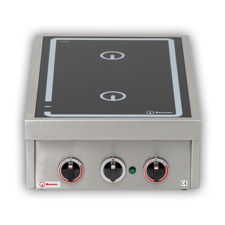
System 60/20; System 70/20;
System 70; Stand stoves;
Be sure to read the instructions for use and assembly
before installation - installation - commissioning.
This protects you and prevents damage.
Berner@induktion.de
Manual
Induction devices
Stool cooker
|
www.induktion.de
Advertisement
Table of Contents


Need help?
Do you have a question about the System 60/20 and is the answer not in the manual?
Questions and answers