
Related Manuals for AXIOMTEK IMB700


Summary of Contents for AXIOMTEK IMB700
- Page 1 IMB700 ® ® Intel LGA4189 Xeon Scalable Ice Lake-SP Processor ATX Industrial Motherboard with 3 PCIe x16, 3 PCIe x8, VGA, NVMe User’s Manual...
- Page 2 Axiomtek does not make any commitment to update the information in this manual. Axiomtek reserves the right to change or revise this document and/or product at any time without notice. No part of this document may be reproduced, stored in a retrieval system, or transmitted, in any form or by any means, electronic, mechanical, photocopying, recording, or otherwise, without the prior written permission of Axiomtek Co., Ltd.
-
Page 3: Esd Precautions
◼ Wear a grounding wrist strap, available from most electronic component stores, when handling boards and components. Trademarks Acknowledgments Axiomtek is a trademark of Axiomtek Co., Ltd. ® ® Intel and Celeron are trademarks of Intel Corporation. -
Page 4: Table Of Contents
Table of Contents Disclaimers ...................... ii ESD Precautions ..................... iii Section 1 Introduction ..........1 Features ....................2 Specifications ..................2 Packing list .................... 4 Section 2 Board and Pin Assignments ....5 Board Layout ..................5 Rear I/O ....................6 Block Diagram .................. - Page 5 Section 3 Hardware Description ......27 Microprocessors .................. 27 BIOS....................27 System Memory .................. 27 Section 4 AMI BIOS Setup Utility ......29 Starting ....................29 Navigation Keys .................. 29 Main Menu ..................31 Advanced Menu .................. 32 Platform Configuration................. 43 Socket Configuration ................
- Page 6 This page is intentionally left blank.
-
Page 7: Introduction
Section 1 Introduction The IMB700 is an advanced ATX industrial severboard based on the Intel® Xeno® Scalable Ice Lake-SP processors in an LGA4189 socket, and comes with an Intel® C621A chipset. Featuring enhanced computing power to deliver optimal computing and visual performance, the IMB700 motherboard is an ideal solution for developing major industry applications ranging from financial modeling to deep learning AI and video surveillance. -
Page 8: Features
IMB700 LGA4189 ATX Motherboard Features ⚫ Intel® Xeon® Scalable Ice Lake-SP platform up 270W ⚫ Six 288-pin DDR4-3200 RDIMM, LRDIMM for up to 384GB of memory ⚫ 3 PCIe x16, 3 PCIe x8 ⚫ Supports M.2 Key M ⚫ TPM 2.0 supported (optional) ⚫... - Page 9 IMB700 LGA4189 ATX Motherboard ⚫ Ethernet ◼ LAN1: 1000/100/10Mbps Gigabit/Fast Ethernet supports Wake-on-LAN, PXE Boot ® ROM with Intel i210-AT ◼ LAN2: 1000/100/10Mbps Gigabit/Fast Ethernet supports Wake-on-LAN, PXE Boot ® ROM with Intel i210-AT ⚫ Storage ◼ 6 x SATAIII with RAID 0/1/5/10 ◼...
-
Page 10: Packing List
IMB700 LGA4189 ATX Motherboard Packing list Bulk packing ⚫ ◼ 1 x Motherboard ◼ 1 x I/O bracket Gift box ⚫ 1 x Motherboard ◼ 1 x I/O bracket ◼ Introduction... -
Page 11: Board And Pin Assignments
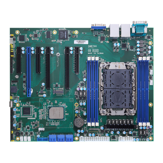
IMB700 LGA4189 ATX Motherboard Section 2 Board and Pin Assignments Board Layout Top side Board and Pin Assignments... -
Page 12: Rear I/O
IMB700 LGA4189 ATX Motherboard Rear I/O I/O side I/O bracket Board and Pin Assignments... -
Page 13: Block Diagram
IMB700 LGA4189 ATX Motherboard Block Diagram Board and Pin Assignments... -
Page 14: Jumper Settings
⚫ used for pin 1. Before applying power to the IMB700 series, make sure all of the jumpers are in factory default position. Below you can find a summary table of all jumpers and onboard default settings. Turn off power before changing any default jumper settings. -
Page 15: Temperature Sensor Source Select (Jp2)
IMB700 LGA4189 ATX Motherboard 2.4.1 Temperature Sensor Source Select (JP2) Use these jumpers (3x1-pin p=2.54mm) to set temperature sensor source to operate from an external sensor or in onboard mode. Function Setting External Sensor (CN5) 1-2 close Onboard Sensor (Default) 2-3 close An external sensor can be installed at 1-2. -
Page 16: At/Atx Mode Select (Jp20)
IMB700 LGA4189 ATX Motherboard 2.4.4 AT/ATX Mode Select (JP20) This 3x1-pin p=2.54mm jumper allows you to select AT or ATX power mode. Function Setting AT mode (Default) 1-2 close ATX mode 2-3 close Board and Pin Assignments... -
Page 17: Connectors
IMB700 LGA4189 ATX Motherboard Connectors Signals go to other parts of the system through connectors. Loose or improper connection might cause problems, Make sure all connectors are properly and firmly connected. Here is a summary table showing the connectors on the hardware. -
Page 18: Vga Connector (Cn1)
IMB700 LGA4189 ATX Motherboard 2.5.1 VGA Connector (CN1) The 15-pin D-Sub connector is commonly used for VGA display. Signal Signal Green Blue DDC DATA Horizontal Sync Vertical Sync DDC CLK 2.5.2 LAN and USB 3.1 Connectors (CN3 and CN4) The motherboard comes with two high performance plug and play Ethernet interfaces (RJ-45) which are fully pliant with the IEEE 802.3 standard. -
Page 19: Gpio Header (Cn6)
IMB700 LGA4189 ATX Motherboard 2.5.4 GPIO Header (CN6) This header (5x2-pin p=2.00mm) is for digital I/O interface. Signal Signal DIO1 DIO8 DIO2 DIO7 DIO3 DIO6 DIO4 DIO5 The default value of DIO1 to DIO8 is set as GPI with high level. -
Page 20: 2280 Key M Pcie X4 Ssd Slot (Cn12)
IMB700 LGA4189 ATX Motherboard 2.5.6 M.2 2280 Key M PCIe x4 SSD slot (CN12) The IMB700 comes with one M.2 2280 Key M slot with PCIe x4 signal for NVMe SSD storage. Signal Signal Signal Signal +3.3V +3.3V PEX3_RX- PEX3_RX+... -
Page 21: Voltage Monitor Header (Cn15)
IMB700 LGA4189 ATX Motherboard 2.5.8 Voltage Monitor Header (CN15) CN27 (8x1-pin p=2.54mm) is used for voltage monitoring and doesn’t supply power. Signal Signal VCC5_SB +3.3V -12V +12V 2.5.9 Front Panel Header (CN16) This is a front panel header (7x2-pin p=2.54mm). -
Page 22: Power Input Connectors (Atx1, Atx2, Cn18 And Cn19)
IMB700 LGA4189 ATX Motherboard 2.5.10 Power Input Connectors (ATX1, ATX2, CN18 and CN19) Steady and sufficient power can be supplied to all components on the motherboard by connecting the power connector. Please make sure all components and devices are properly installed before connecting the power connector. -
Page 23: Internal Usb 3.1 Gen1 Connector (Cn20)
IMB700 LGA4189 ATX Motherboard 2.5.11 Internal USB 3.1 Gen1 Connector (CN20) The CN20 is a 19-pin internal connector for installing versatile USB 3.1 compliant peripherals. Signal Signal VBUS0 SSRX5- VBUS1 SSRX5+ SSRX6- SSRX6+ SSTX5- SSTX5+ SSTX6- SSTX6+ USB10- USB10+ USB11- USB11+ 2.5.12... -
Page 24: Fan Connectors (Fan1~Fan3 And Fan5~6)
IMB700 LGA4189 ATX Motherboard 2.5.13 Fan Connectors (FAN1~FAN3 and FAN5~6) This motherboard has five fan connectors. Find fan speed option(s) at BIOS Setup Utility: Advanced\HW Monitor\PC Health Status. FAN1~3 and FAN6 (4x1-pin p=2.54mm) is for the the system fan connectors. -
Page 25: Sata 3.0 Connectors (Sata1 ~ Sata6)
IMB700 LGA4189 ATX Motherboard 2.5.15 SATA 3.0 Connectors (SATA1 ~ SATA6) These Serial Advanced Technology Attachment (Serial ATA or SATA) connectors are for SATA 3.0 interface allowing up to 6.0Gb/s data transfer rate. It is a computer bus interface for connecting to devices such as a hard disk drive. -
Page 26: Intel ® Hd Audio Digital Header (Hda1)
IMB700 LGA4189 ATX Motherboard ® 2.5.19 Intel HD Audio Digital Header (HDA1) This is a 2x8-pin header for connecting an external HD Audio board (AX93242). Signal Signal BCLK RST# SYNC +3.3S SDIO +12VS Board and Pin Assignments... -
Page 27: Hardware Installation
IMB700 LGA4189 ATX Motherboard Hardware Installation This section provides information on how to install the IMB700 Series. 2.6.1 Installing the CPU The LGA4189 processor socket comes with a cover to protect the processor. Please install the processor into the CPU socket step by step as illustrated below. - Page 28 IMB700 LGA4189 ATX Motherboard This sequence is for installing the CPU cooler under 205 Watts: Step 1 Remove the socket protective covers. Press the load lever and release it from the retention tab. There are two levers for each CPU socket.
- Page 29 IMB700 LGA4189 ATX Motherboard Step 3 Check the notch on the CPU and the pin on the CPU socket of IMB700. Load lever Notch Follow the installation direction and Install the CPU clip and CPU on the cooler module. Load lever...
- Page 30 IMB700 LGA4189 ATX Motherboard Step 4 Place the CPU cooler module on the CPU socket on the motherboard, and then align pin A to hole A and pin B to hole B simultaneously. Hole A Pin A Pin B Hole B...
- Page 31 IMB700 LGA4189 ATX Motherboard Step 5 Latch four levers on the cooler. Step 6 Use a T30 Torx screwdriver (8in-LBF) to tighten the screws on the cooler. Board and Pin Assignments...
- Page 32 IMB700 LGA4189 ATX Motherboard This sequence is for installing the CPU cooler above 205 Watts: Repeat step1 to 3 for installing CPU on CPU cooler. Step 7 Latch four levers on the cooler. Step5 Put the fan module on the CPU cooler and tighten two screws (8in-LBF).
-
Page 33: Hardware Description
The IMB700 series uses AMI Plug and Play BIOS. System Memory The IMB700 supports six 288-pin DDR4 RDIMM sockets for maximum memory capacity up to 384GB of DDR4 RAMs. The memory module comes in sizes of 16GB, 32GB, and 64GB. - Page 34 IMB700 LGA4189 ATX Motherboard This page is intentionally left blank. Hardware Description...
-
Page 35: Ami Bios Setup Utility
IMB700 LGA4189 ATX Motherboard Section 4 AMI BIOS Setup Utility The AMI UEFI BIOS provides users with a built-in setup program to modify basic system configuration. All configured parameters are stored in a flash chip to save the setup information whenever the power is turned off. - Page 36 IMB700 LGA4189 ATX Motherboard Hot Keys Description → Left/Right The Left and Right <Arrow> keys allow you to select a setup screen. The Up and Down <Arrow> keys allow you to select a setup screen or sub Up/Down screen.
-
Page 37: Main Menu
IMB700 LGA4189 ATX Motherboard Main Menu When you first enter the setup utility, you will enter the Main setup screen. You can always return to the Main setup screen by selecting the Main tab. System Time/Date can be set up as described below. -
Page 38: Advanced Menu
IMB700 LGA4189 ATX Motherboard Advanced Menu The Advanced menu also allows users to set configuration of the CPU and other system devices. You can select any of the items in the left frame of the screen to go to the sub menus: ►... - Page 39 IMB700 LGA4189 ATX Motherboard ⚫ Trusted Computing Enable or disable security device support. AMI BIOS Setup Utility...
- Page 40 IMB700 LGA4189 ATX Motherboard ⚫ F81803 Super IO Configuration You can use this screen to select options for the Super IO Configuration, and change the value of the selected option. A description of the selected item appears on the right side of the screen.
- Page 41 IMB700 LGA4189 ATX Motherboard ⚫ Hardware Monitor This screen monitors hardware health status. This screen displays the temperature of system and CPU, cooling fans speed in RPM and system voltages (VCC3V, VIN2, VBAT, +5VSBY and VIN1). CPU FAN = FAN5; SYS FA = FAN6.
- Page 42 IMB700 LGA4189 ATX Motherboard ⚫ NCT7802YHardware Monitor This screen monitors hardware health status. This screen displays the temperature of system, cooling fans speed in RPM and system voltages. SYS FA = FAN1, 2 & 3. Note AMI BIOS Setup Utility...
- Page 43 IMB700 LGA4189 ATX Motherboard ⚫ Serial Port Console Redirection This screen allows you to set serial port console redirection. AMI BIOS Setup Utility...
- Page 44 IMB700 LGA4189 ATX Motherboard ⚫ PCI Subsystem Settings This screen allows you to set PCI Subsystem mode. Above 4G Decoding Ebable or disable above 4G decoding. SR-IOV Support Ebable or disable SR-IOV support. BME DMA Mitigation Ebable or disable BME DMA Mitigation.
- Page 45 IMB700 LGA4189 ATX Motherboard ⚫ USB Configuration This screen shows USB configuration. USB Devices Displays all detected USB devices. Legacy USB Support Enables Legacy USB support. The AUTO option disables legacy support if no USB devices are connected. XHCI Hand-off This is a workaround for OSes without XHCI hand-off support.
- Page 46 IMB700 LGA4189 ATX Motherboard ⚫ Network Stack Configuration On this screen, you can select PXE LAN port. AMI BIOS Setup Utility...
- Page 47 IMB700 LGA4189 ATX Motherboard ⚫ CSM (Compatibility Support Module) Configuration This screen displays CSM information. CSM Support Enabled / Disable CSM Support. GateA20 Active UPON REQUEST - GA20 can be disabled using BIOS services. ALWAYS - do not allow disabling GA20. This option is useful when any RT code is executed above 1MB.
- Page 48 IMB700 LGA4189 ATX Motherboard Video Controls the execution of UEFI and Legacy Video OpROM. Other PCI devices Determines OpROM execution policy for devices other than Network, Storage, or Video. AMI BIOS Setup Utility...
-
Page 49: Platform Configuration
IMB700 LGA4189 ATX Motherboard Platform Configuration The Chipset menu allows users to change the advanced chipset settings. You can select any of the items in the left frame of the screen to go to the sub menus: ► PCH Configuration ►... - Page 50 IMB700 LGA4189 ATX Motherboard ⚫ PCH Devices The screen shows PCH devices. Wake From DeepSx Enable or disable the GP27 Wake From DeepSx. AMI BIOS Setup Utility...
- Page 51 IMB700 LGA4189 ATX Motherboard ⚫ PCI Express Configuration The screen shows PCI Express Configuration. AMI BIOS Setup Utility...
- Page 52 IMB700 LGA4189 ATX Motherboard ⚫ PCH SATA Configuration During system boot up, the BIOS automatically detects the presence of SATA devices. In the SATA Configuration menu, you can see the hardware currently installed in the SATA ports. SATA Controller(s) Enable or disable the SATA Controller feature. The default is Enabled.
- Page 53 IMB700 LGA4189 ATX Motherboard ⚫ Azalia Configuration This screen shows Azalia configuration. AMI BIOS Setup Utility...
-
Page 54: Socket Configuration
IMB700 LGA4189 ATX Motherboard Socket Configuration The socket configuration menu allows users to change the advanced socket settings. ► Processor Configuration ► IIO Configuration For items marked with “”, please press <Enter> for more options. AMI BIOS Setup Utility... - Page 55 IMB700 LGA4189 ATX Motherboard ⚫ Processor Configuration This screen shows processor information and set TME function. Total Memory Encryption (TME) Enable or disable the TME function. AMI BIOS Setup Utility...
- Page 56 IMB700 LGA4189 ATX Motherboard ⚫ IIO Configuration This screen shows the IO configuration information. AMI BIOS Setup Utility...
-
Page 57: Security Menu
IMB700 LGA4189 ATX Motherboard Security Menu The Security menu allows users to change the security settings for the system. Administrator Password This item indicates whether an administrator password has been set (installed or uninstalled). User Password This item indicates whether a user password has been set (installed or uninstalled). -
Page 58: Boot Menu
IMB700 LGA4189 ATX Motherboard Boot Menu The Boot menu allows users to change boot options of the system. Setup Prompt Timeout Enter the number of seconds to wait for the setup activation key. 65535(0xFFFF) means indefinite waiting. Bootup NumLock State Use this item to select the power-on state for the keyboard NumLock. -
Page 59: Save & Exit Menu
IMB700 LGA4189 ATX Motherboard Save & Exit Menu The Save & Exit menu allows users to load your system configuration with optimal or fail-safe default values. Save Changes and Exit When you have completed the system configuration changes, select this option to leave Setup and return to Main Menu. - Page 60 IMB700 LGA4189 ATX Motherboard Save Changes When you have completed the system configuration changes, select this option to save changes. Select Save Changes from the Save & Exit menu and press <Enter>. Select Yes to save changes. Discard Changes Select this option to quit Setup without making any permanent changes to the system configuration.
-
Page 61: Appendix A Watchdog Timer
IMB700 LGA4189 ATX Motherboard Appendix A Watchdog Timer About Watchdog Timer Software stability is a major issue in most applications. Some embedded systems are not watched by humans for 24 hours. It is usually too slow to wait for someone to reboot when computer hangs. - Page 62 IMB700 LGA4189 ATX Motherboard Note: If N=00h, the time base is set to second. M = time value 00h: Time-out Disable 01h: Time-out occurs after 1 second 02h: Time-out occurs after 2 seconds 03h: Time-out occurs after 3 seconds FFh: Time-out occurs after 255 seconds If N=08h, the time base is set to minute.
-
Page 63: Appendix B Tpm Module Installation
The TPM 2.0 (Trusted Platform Module 2.0) module is a modularized design applying to the IMB700 and provides enhanced hardware security for the computer. In this appendix you will learn how to install the TPM 2.0 module into the IMB700. Please read and follow the instructions below carefully. - Page 64 IMB700 LGA4189 ATX Motherboard (In the Advance menu, go to Trusted Computing) (In the Trusted Computing section, the first line will show “TPM2.0 Device Found”, if installation is successful.) b. In the Windows 10 OS environment, enter Device Manager, and select the item of Security devices.
- Page 65 IMB700 LGA4189 ATX Motherboard c. In the Windows 10 OS environment, enter Control Panel, select the item of BitLocker Drive Encryption, and enter TPM Administration. The screen will show the information below if installation is successful. iAMT Settings...
- Page 66 IMB700 LGA4189 ATX Motherboard This page is intentionally left blank. iAMT Settings...
-
Page 67: Appendix C Configuring Sata For Raid
IMB700 LGA4189 ATX Motherboard Appendix C Configuring SATA for RAID Configuring SATA Hard Drive(s) for RAID Function Before you begin the SATA configuration, please prepare: Two SATA hard drives (to ensure optimal performance, it is recommended that you use ⚫... - Page 68 IMB700 LGA4189 ATX Motherboard Turn on your system, and then press the <Del> button to enter BIOS Setup during running 2.1. POST (Power-On Self Test). If you want to create RAID, just go to the Platform configuration/PCH SATA Configuration, select the “Configuration SATA as”, and press <Enter>...
- Page 69 IMB700 LGA4189 ATX Motherboard Enable the Load EFI Driver for RAID. 2.2. Under the Boot Settings menu, set DVD-ROM for First Boot Option to boot DVD-ROM 2.3. after system restarts. Configuring SATA for RAID...
- Page 70 IMB700 LGA4189 ATX Motherboard Go to the Advanced screen, select the “Intel(R) VROC SATA Controller”; furtherly, select 2.4. the ”Cerate RAID Volume” and press <Enter> for more options. Configuring SATA for RAID...
- Page 71 IMB700 LGA4189 ATX Motherboard Select the “RAID Level”, and choose RAID0, 1 or 5 for youe needs. 2.5. Save and exit the BIOS Setup. 2.6. Configuring SATA for RAID...
- Page 72 IMB700 LGA4189 ATX Motherboard This page is intentionally left blank. Configuring SATA for RAID...
-
Page 73: Appendix D Digital I/O
IMB700 LGA4189 ATX Motherboard Appendix D Digital I/O Digital I/O Software Programming ⚫ I2C to GPIO PCA9554PW GPIO[3:0] is Output, GPIO[7:4] is Input. I2C address: 0b0100100x. ⚫ IOBASE: 0xF040 ⚫ Registers: ⚫ Command byte Command Protocol Function Read byte Input port register... - Page 74 IMB700 LGA4189 ATX Motherboard Register 1: Output port register. This register reflects the outgoing logic levels of the pins defined as outputs by Register 3. Bit values in this register have no effect on pins defined as inputs. Reads from this register return the value that is in the flip-flop controlling the output selection, not the actual pin value.
Need help?
Do you have a question about the IMB700 and is the answer not in the manual?
Questions and answers