
Related Manuals for AXIOMTEK IMB541


Summary of Contents for AXIOMTEK IMB541
- Page 1 IMB541 ® Intel Socket 1700 Core i9/i7/ i5/ i3 ® ® /Pentium / Celeron and Xeon® E Processors ATX Industrial Motherboard User’s Manual...
-
Page 2: Disclaimers
Axiomtek does not make any commitment to update the information in this manual. Axiomtek reserves the right to change or revise this document and/or product at any time without notice. No part of this document may be reproduced, stored in a retrieval system, or transmitted, in any form or by any means, electronic, mechanical, photocopying, recording, or otherwise, without the prior written permission of Axiomtek Co., Ltd. -
Page 3: Esd Precautions
To discharge static electricity from your body. ◼ Wear a grounding wrist strap, available from most electronic component stores, when handling boards and components. Trademarks Acknowledgments Axiomtek is a trademark of Axiomtek Co., Ltd. ® ® Intel and Celeron are trademarks of Intel Corporation. -
Page 4: Table Of Contents
Table of Contents Disclaimers ...................... ii ESD Precautions ..................... iii Section 1 Introduction ..........1 Features ....................2 Specifications ..................2 Packing list .................... 3 Section 2 Board and Pin Assignments ....5 Board Layout ..................5 Block Diagram ..................6 Jumper Settings .................. - Page 5 2.3.27 Fan Connectors (CPU_FAN1, SYS_FAN1, SYS_FAN2) ......22 2.3.28 PCI-Express x4 Slots (PCIE_4X_SLOT1, SLOT2, SLOT3, SLOT4) ..23 2.3.29 SATA 3.0 Connectors (SATA1-2, SATA3-4) ..........24 Section 3 Hardware Description ......25 Microprocessors .................. 25 BIOS....................25 System Memory .................. 25 Section 4 AMI BIOS Setup Utility ......
- Page 6 This page is intentionally left blank.
-
Page 7: Introduction
IMB540 User’s manual Section 1 Introduction The IMB541 is an advanced ATX industrial motherboard based on the 12 Generation Intel® Core™ i9 / i7/ i5/ i3/ Pentium®, Celeron® processors (Alder lake S) in an LGA1700 socket and comes with an Intel® Q670E chipset. Specially designed for optimal computing and visual performance, the IMB541 motherboard is an ideal solution for major industry applications ranging from financial modeling to designing complex buildings and vehicles. -
Page 8: Features
IMB541 User’s manual Features Generation Intel® Core™ i9 / i7/ i5/ i3/ Pentium®, Celeron® ⚫ LGA1700 socket 12 processors (Alder lake S) up to 125W ⚫ 4 x 288-pin DDR4-3200 Non-ECC un-buffered Long-DIMM with maximum memory capacity up to 128GB (max. 32GB per slot) ⚫... -
Page 9: Packing List
IMB540 User’s manual ⚫ Display ◼ 1 x DVI :Support DVI-D, max resolution up to 1920x1200@60Hz ◼ 1 x HDMI 1.4b (TYPE-A): up to 4096x2160@30Hz ◼ 1 x VGA (DB15/F): max resolution up to 1920x1200@60Hz ⚫ Expansion Interface ◼ 1 x PCI-E x16 Slot (PCIe x16, GEN4) ◼... - Page 10 IMB541 User’s manual This page is intentionally left blank. Introduction...
-
Page 11: Board And Pin Assignments
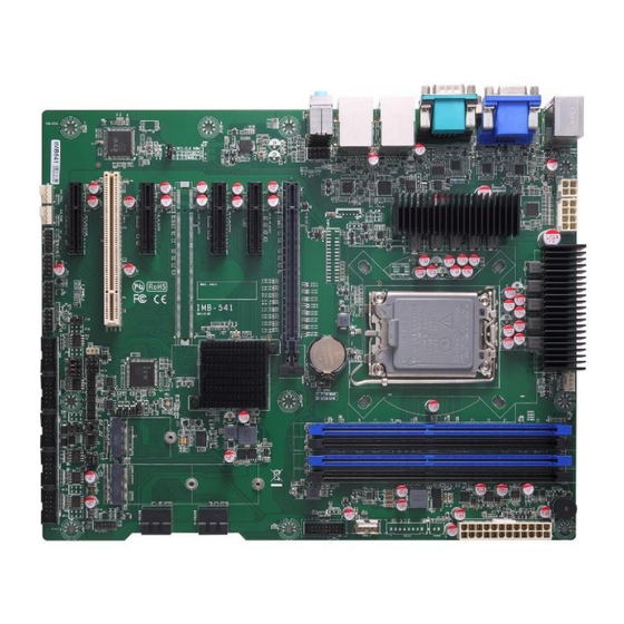
IMB540 User’s manual Section 2 Board and Pin Assignments Board Layout Top side Board and Pin Assignments... -
Page 12: Block Diagram
IMB541 User’s manual Block Diagram Board and Pin Assignments... -
Page 13: Jumper Settings
A square pad, which you can find on the back of the motherboard, is ⚫ usually used for pin 1. Before applying power to the IMB541 series , make sure all of the jumpers are in motherboard factory default position. Below you can find a summary table of all jumpers and onboard default settings. - Page 14 IMB541 User’s manual Signals go to other parts of the system through connectors. Loose or improper connection might cause problems. Make sure all connectors are properly and firmly connected. Here is a summary table showing the connectors on the motherboard.
- Page 15 IMB540 User’s manual DIMM2 DDR4 CHB DIMM Slo3 DIMM3 DDR4 CHA DIMM Slot2 DIMM1 DDR4 CHA DIMM Slot1 PCIE_16X_SLOT1 PCI-E 16x Slot1 (PCIe 4X) PCIE_4X_SLOT1 PCI-E 4x Slot1 (PCIe 4X) PCIE_4X_SLOT2 PCI-E 4x Slot2 (PCIe 3X) PCIE_4X_SLOT3 PCI-E 4x Slot3 (PCIe 4X) PCIE_4X_SLOT4 PCI-E 4x Slot4 (PCIe 4X) PCI1...
-
Page 16: Ps/2 Connector (Keyboard & Mouse) And Dual Usb3.0 Type-A Connector (Ps/2_Usb1)
IMB541 User’s manual 2.3.3 PS/2 Connector (Keyboard & Mouse) and Dual USB3.0 TYPE-A Connector (PS/2_USB1) PS/2_USB1 is a double-deck connector comprised of an upper connector for PS (PS/2) and a lower connector for USB (USB1). Signal Keyboard Data Mouse Data... -
Page 17: Hdmi Connector (Hdmi1)
IMB540 User’s manual 2.3.5 HDMI Connector (HDMI1) connector for HDMI (HDMI1). Signal TMDS Data2+ TMDS Data2– TMDS Data1+ TMDS Data1– TMDS Data0+ TMDS Data0– TMDS Clock+ TMDS Clock– Reserved(N.C. on device) DDC/CEC Ground +5V Power Hot Plug Detect Board and Pin Assignments... -
Page 18: Vga And Dvi-D Connector (Vga1, Dvi1)
IMB541 User’s manual 2.3.6 VGA and DVI-D Connector (VGA1, DVI1) is a double-deck connector comprising a lower connector for DVI-D port and an upper connector for VGA port. The high rise DVI-D connector provides transmission of fast and high quality video signals between a source device (graphic card) and a display device (monitor). -
Page 19: Front Audio Header (F_Audio1)
IMB540 User’s manual 2.3.8 Front Audio Header (F_AUDIO1) This is a front audio header (5x2-pin p=2.54mm) for convenient connection and control of audio devices. Signal Signal MIC_IN_L MIC_IN_R VCC3.3 LINE_OUT_R MIC_RET LINE_OUT_L LINE_OUT_RET 2.3.9 LAN and USB 3.2 Connectors (RJ45_USB1 and RJ45_USB2) The motherboard comes with two high performance plug and play Ethernet interfaces (RJ-45) which are fully compliant with the IEEE 802.3 standard. -
Page 20: Gpio Header (J_Gpio1)
IMB541 User’s manual USB Signal USB Signal USB3_POWER USB1 - USB1 + USB3_SSRX1- USB3_SSRX1+ USB3_SSTX1- USB3_SSTX1+ USB3_POWER USB2 - USB2 + USB3_SSRX2- USB3_SSRX2+ USB3_SSTX2- USB3_SSTX2+ 2.3.10 GPIO Header (J_GPIO1) This header (6x2-pin p=2.00mm) is for digital I/O interface. Signal Signal... -
Page 21: 2280 Key M Nvme Ssd (M.2_Pciessd_M1)
IMB540 User’s manual 2.3.13 M.2 2280 Key M NVMe SSD (M.2_PCIESSD_M1) The M.2_PCIESSD_M1 (5x1-pin p=2.00mm) is for SMBus (System Management Bus) interface. Signal Signal Signal Signal +3.3V +3.3V PERn3 PERp3 LED_1# PETn3 +3.3V PETp3 +3.3V +3.3V PERn2 +3.3V PERp2 PETn2 PETp2 PERn1 PERp1... -
Page 22: Key E Socket (M.2_Keye_Wlan1)
IMB541 User’s manual 2.3.14 M.2 Key E Socket (M.2_KEYE_WLAN1) The motherboard comes with one M.2 Key E socket (PCIe & USB2.0) M.2_KEYE_WLAN1 (5x1-pin p=2.00mm) supports CNVi module CNVi, the integrated wireless IP portion of Intel processors I/O Interface is Intel's proprietary connectivity interface for Wi-Fi and Bluetooth... -
Page 23: Smbus Header (Smbus1)
IMB540 User’s manual 2.3.15 SMBus Header (SMBUS1) The SMBUS1 (4x1-pin p=1.25mm) is for SMBus (System Management Bus) interface. Signal Signal SMB_DATA SMB_CLK Power on this Pin is 5V by default, 3.3V is available if specified. (resistor selectable) Note 2.3.16 Internal USB Headers (F_USB2_1, F_USB2_2 , USB2_1) These are 5x2-pin p=2.54mm headers for USB 2.0 interface. -
Page 24: Espi Header (Debug Only) 6*2 Pin 2.00Mm)
IMB541 User’s manual 2.3.17 ESPI Header (Debug Only) 6*2 Pin 2.00mm) Signal Signal ESPI_IO0 VCC3.3_Dual ESPI_IO1- ESPI_IO2 ESPI_CLK ESPI_IO3 ESPI_CS0 VCC3.3S ESPI_ALERT0_N PLT_RST_N 2.3.18 Front Panel Header (F_PANEL1 ) This is a front panel header (5x2-pin p=2.54mm). Signal HD LED+... -
Page 25: Power Input Connectors (Atx1 And Atx2 And Atx3)
IMB540 User’s manual 2.3.19 Power Input Connectors (ATX1 and ATX2 and ATX3) Steady and sufficient power can be supplied to all components on the motherboard by connecting the power connector. Please make sure all components and devices are properly installed before connecting the power connector. An external power supply plug fits into ATX1 and ATX2 and ATX3 in only one orientation. -
Page 26: Internal Usb 3.2 Gen1 (5Gbps) Connector (F_Usb3_1)
IMB541 User’s manual 2.3.20 Internal USB 3.2 Gen1 (5Gbps) Connector (F_USB3_1) The F_USB3_1 is a 19-pin internal connector for installing various USB 3.2 Gen1(5Gbps) compliant peripherals. Signal Signal VBUS0 SSRX5- VBUS1 SSRX5+ SSRX6- SSRX6+ SSTX5- SSTX5+ SSTX6- SSTX6+ USB10- USB10+... -
Page 27: Com4 Rs485 Signal 120Ω Resistive Termination Select Jumper(Jp17)
IMB540 User’s manual 2.3.23 COM4 RS485 Signal 120Ω Resistive termination Select Jumper(JP17) Use these jumpers (3x1-pin p=2.54mm) to set signal Function Setting Disable (Default) 1-2 close Enable 2-3 close 2.3.24 COM BOX Headers (COM2, COM3, COM4, COM5, COM6) The motherboard comes with 5x2-pin p=2.54mm box headers for COM serial port interfaces. -
Page 28: Com4 Mode Select (Jp7, Jp18)
IMB541 User’s manual 2.3.26 COM4 Mode Select (JP7, JP18) Use these jumpers (3x2-pin p=2.54mm) to set COM4 port to operate in RS-232 or RS-485 communication mode. Function Setting JP18: 1-2 RS232(Default) JP7: 3-5、4-6(Default) JP18: 5-6 RS485 JP7: 1-3、2-4 COM3 and COM4 are RS232 by default. COM3 can be RS485 or RS422 selecting by jumper and setting BIOS to RTS mode. -
Page 29: Pci-Express X4 Slots (Pcie_4X_Slot1, Slot2, Slot3, Slot4)
IMB540 User’s manual 2.3.28 PCI-Express x4 Slots (PCIE_4X_SLOT1, SLOT2, SLOT3, SLOT4) This motherboard has four PCI-Express x4 slots Signal Signal +12V_PS +12V_PS +12V_PS +12V_PS +12V_PS SMB_CLK_RESUME SMB_DATA_RESUME +3.3V_PS +3.3V_PS +3.3V_SB +3.3V_PS PCH_WAKE_N PWRGD CLKOUT_PCIE_P5 PCIE1_SLOT1_TX_DP_C CLKOUT_PCIE_N5 PCIE1_SLOT1_TX_DN_C PCIE1_SLOT1_RX_DP_C PCIEX4_SLOT1_PRSNT2_N PCIE1_SLOT1_RX_DN_C PCIE2_TX_DP PCIE2_TX_DN PCIE2_RX_DP... -
Page 30: Sata 3.0 Connectors (Sata1-2, Sata3-4)
IMB541 User’s manual 2.3.29 SATA 3.0 Connectors (SATA1-2, SATA3-4) These Serial Advanced Technology Attachment (Serial ATA or SATA) connectors are for SATA 3.0 interface allowing up to 6.0Gb/s data transfer rate. It is a computer bus interface for connecting to devices such as hard disk drive. -
Page 31: Hardware Description
The IMB541 series uses AMI Plug and Play BIOS. System Memory The IMB541 supports four 288-pin DDR4 DIMM sockets for maximum memory capacity up to 128GB DDR4 SDRAMs. The memory module comes in sizes of 2GB, 4GB, 8GB, 16GB and 32GB. - Page 32 IMB541 User’s manual This page is intentionally left blank. Hardware Description...
-
Page 33: Ami Bios Setup Utility
IMB540 User’s manual Section 4 AMI BIOS Setup Utility The AMI UEFI BIOS provides users with a built-in setup program to modify basic system configuration. All configured parameters are stored in a flash chip to save the setup information whenever the power is turned off. This chapter provides users with detailed description about how to set up basic system configuration through the AMI BIOS setup utility. - Page 34 IMB541 User’s manual Hot Keys Description → Left/Right The Left and Right <Arrow> keys allow you to select a setup screen. The Up and Down <Arrow> keys allow you to select a setup screen or sub Up/Down screen. The <Enter> key allows you to display or change the setup option listed for a Enter particular setup item.
-
Page 35: Main Menu
IMB540 User’s manual Main Menu When you first enter the setup utility, you will enter the Main setup screen. You can always return to the Main setup screen by selecting the Main tab. System Time/Date can be set up as described below. -
Page 36: Advanced Menu
IMB541 User’s manual Advanced Menu The Advanced menu also allows users to set configuration of the CPU and other system devices. You can select any of the items in the left frame of the screen to go to the sub menus: ►... - Page 37 IMB540 User’s manual ⚫ ACPI Settings It shows advanced configuration and power interface and hardware components to perform power management and status monitoring ⚫ Trusted Computing Enable or disable security device support. AMI BIOS Setup Utility...
- Page 38 IMB541 User’s manual ⚫ Platform Misc Configuration This screen allows you to set Platform Misc Configuration. Native PCIE Enable Bit - PCIe Native * control 0 - ~ Hot Plug 1 - SHPC Native Hot Plug control 2 - ~ Power Management Events 3 - PCIe Advanced Error Reporting control 4 - PCIe Capability Structure control 5 - Latency Tolerance Reporting control.
- Page 39 IMB540 User’s manual ⚫ CPU Configuration This screen shows CPU information, and you can change the value of the selected option. Hardware Prefetcher Turn on/off the MLC streamer prefetcher. Adjacent Cache Line Prefetch Turn on/off prefetching of adjacent cache lines. Package C State Limit Maximum Package C State Limit Setting.
- Page 40 IMB541 User’s manual Enable / Disable AES (Advanced Encryption Standard) Boot performance mode Select the performance mode that the BIOS will run after the reset. Intel (R) SpeedStep(tm) Allows more than two frequency ranges to be supported. ⚫ Storage Configuration This screen shows storage information.
- Page 41 IMB540 User’s manual ⚫ SATA Configuration During system boot up, the BIOS automatically detects the presence of SATA devices. In the SATA Configuration menu, you can see the hardware currently installed in the SATA ports. SATA Controller(s) Enable or disable the SATA Controller feature. The default is Enabled. VMD Setup Menu VMD Configuration settings.
- Page 42 IMB541 User’s manual ⚫ NVMe Configuration This screen shows NVMe device information. AMI BIOS Setup Utility...
- Page 43 IMB540 User’s manual ⚫ IT8786 Super IO Configuration You can use this screen to select options for the Super IO Configuration, and change the value of the selected option. A description of the selected item appears on the right side of the screen.
- Page 44 IMB541 User’s manual ⚫ Serial Port 1 Configuration Use these items to set parameters related to serial port 1 and 2. Serial Port 1 This item allows you to use RS232 only . Serial Port 2 This item allows you to use RS232 only .
- Page 45 IMB540 User’s manual Serial Port 3 This item allows you to use it as RS232/422/485. The default is RS232. AMI BIOS Setup Utility...
- Page 46 IMB541 User’s manual Serial Port 4 This item allows you to use it as RS232/485. The default is RS232. Serial Port 5 This item allows you to use RS232 only. Serial Port 6 This item allows you to use RS232 only.
- Page 47 IMB540 User’s manual ⚫ Hardware Monitor This screen monitors hardware health status. This screen displays the temperature of system and CPU, cooling fans speed in RPM and system voltages (VCC_CPU, DDR(VDDQ) +12V, +5V and +3.3V). CPU FAN = CPU FAN Speed; SYS FAN = FAN1/FAN2. (System Smart fan control integrated with fan1/fan2) Note AMI BIOS Setup Utility...
- Page 48 IMB541 User’s manual ⚫ USB Configuration This screen shows USB configuration. AMI BIOS Setup Utility...
- Page 49 IMB540 User’s manual ⚫ PCI Subsystem Settings This screen allows you to set PCI Subsystem mode. PCI Latency Timer Set the value to be programmed into PCI Latency Timer Register. VGA Palette Snoop Enables or Disables VGA Palette Registers Snooping. AMI BIOS Setup Utility...
-
Page 50: Chipset Menu
IMB541 User’s manual Chipset Menu The Chipset menu allows users to change the advanced chipset settings. You can select any of the items in the left frame of the screen to go to the sub menus: ► System Agent (SA) Configuration ►... - Page 51 IMB540 User’s manual ⚫ System Agent (SA) Configuration This screen allows users to configure System Agent (SA) parameters. For items marked with “”, please press <Enter> for more options. VT-d Check to enable VT-d function on MCH. Graphics Configuration Open the sub menu for parameters related to graphics configuration. CPU PCI Express Root Port Set the ASPM Level and PCI Express Speed.
- Page 52 IMB541 User’s manual ⚫ Graphics Configuration This screen shows graphics configuration. Internal Graphics Keep IGFX enabled based on the setup options. AMI BIOS Setup Utility...
- Page 53 IMB540 User’s manual ⚫ CPU PCI Express Root Port This screen shows CPU PCI Express root port information. ASPM Set the ASPM Level:\nForce L0s - Force all links to L0s State\nForce L1 - Force all links to L1 State\nForce L0sL1 - Force all links to L0SL1 State\nDISABLE - Disables ASPM. PCIe Speed Configure PCIe Speed.
- Page 54 IMB541 User’s manual ⚫ PCH-IO Configuration This screen allows you to set PCH parameters. PCI Express Configuration Configure PCIe Speed. PCI Express Root Port 1 = PCIE_4X_SLOT2 PCI Express Root Port 21 = PCIE_4X_SLOT3 PCI Express Root Port 25 = PCIE_4X_SLOT4 HD Audio Configuration Enable or disable HD Audio.
- Page 55 IMB540 User’s manual PCIe Speed Configure PCIe Speed. ASPM Set the ASPM Level:\nForce L1 - Force all links to L1 State\nAUTO - BIOS auto configure\nDISABLE - Disables ASPM. Detect Non-Compliance Device Detect Non-Compliance PCI Express Device. If enabled, it will take more time at POST time.
- Page 56 IMB541 User’s manual ⚫ HD Audio Configuration This screen shows HD Audio information AMI BIOS Setup Utility...
-
Page 57: Security Menu
IMB540 User’s manual Security Menu The Security menu allows users to change the security settings for the system. ⚫ Administrator Password This item indicates whether an administrator password has been set (installed or uninstalled). ⚫ User Password This item indicates whether a user password has been set (installed or uninstalled). ⚫... -
Page 58: Boot Menu
IMB541 User’s manual Boot Menu The Boot menu allows users to change boot options of the system. ⚫ Setup Prompt Timeout Number of seconds to wait for setup activation key. 65535(0xFFFF) means indefinite waiting. ⚫ Bootup NumLock State Use this item to select the power-on state for the keyboard NumLock. -
Page 59: Save & Exit Menu
IMB540 User’s manual Save & Exit Menu The Save & Exit menu allows users to load your system configuration with optimal or fail-safe default values. ⚫ Save Changes and Exit When you have completed the system configuration changes, select this option to leave Setup and return to Main Menu. - Page 60 IMB541 User’s manual ⚫ Save Changes When you have completed the system configuration changes, select this option to save changes. Select Save Changes from the Save & Exit menu and press <Enter>. Select Yes to save changes. ⚫ Discard Changes Select this option to quit Setup without making any permanent changes to the system configuration.
-
Page 61: Appendix Atpm Module Installation
Appendix A TPM Module Installation The TPM 2.0 (Trusted Platform Module 2.0) is design applying to the IMB541 and provides enhanced hardware security for the computer. In this appendix you will learn how to install the TPM 2.0 into the IMB541. Please read and follow the instructions below carefully. - Page 62 IMB541 User’s manual TPM Module Installation...
- Page 63 IMB540 User’s manual c. In the Windows 10 OS environment, enter Control Panel, select BitLocker Drive Encryption, and enter TPM Administration. The screen will show the information below if installation is successful. TPM Module Installation...
- Page 64 IMB541 User’s manual This page is intentionally left blank. TPM Module Installation...
-
Page 65: Appendix B Watchdog Timer
IMB540 User’s manual Appendix B Watchdog Timer A.1 About Watchdog Timer Software stability is a major issue in most applications. Some embedded systems are not watched by humans for 24 hours. It is usually too slow to wait for someone to reboot when computer hangs. - Page 66 IMB541 User’s manual hinstLibDLL = LoadLibrary(TEXT("diodll.dll")); if (hinstLibDLL == NULL) //MessageBox("Load diodll dll error", "", MB_OK); if (hinstLibDLL) lpFnDll_Get_IO = (LPFNDLLGETIOSPACE)GetProcAddress(GetModuleHandle("diodll.dll"), "GetIoSpaceByte"); lpFnDll_Set_IO = (LPFNDLLSETIOSPACE)GetProcAddress(GetModuleHandle("diodll.dll"), "SetIoSpaceByte"); printf("Input Watch Dog Timer type, 1:Second ; 2:Minute :"); scanf("%d",&unit); printf("\nInput Timer to countdown:");...
- Page 67 IMB540 User’s manual lpFnDll_Set_IO(0x2e, 0xF6); lpFnDll_Set_IO(0x2f, WDTtimer); //set watchdog time unit to min lpFnDll_Set_IO(0x2e, 0xF5); WDTDATA = lpFnDll_Get_IO(0x2f); WDTDATA = setbit(WDTDATA, 3); lpFnDll_Set_IO(0x2f, WDTDATA); //start watchdog counting lpFnDll_Set_IO(0x2e, 0xF5); WDTDATA = lpFnDll_Get_IO(0x2f); WDTDATA = setbit(WDTDATA, 5); lpFnDll_Set_IO(0x2f, WDTDATA); system("pause"); return 0; ⚫...
- Page 68 IMB541 User’s manual This page is intentionally left blank. Watchdog Timer...
-
Page 69: Appendix Cvmd(Raid) Configuration
IMB540 User’s manual Appendix C VMD(RAID) Configuration How to Create Raid? Step 1 In SATA Configuration, Enabled VMD Controller and save & reset. VMD(RAID) Configuration... - Page 70 IMB541 User’s manual Step2 After Restart, enter del to Bios Setup Menu. In Advanced Page, choose Intel(R) Rapid Storage Technology. Step3 In Intel(R) Rapid Storage Technology page. Choose RAID Volume. VMD(RAID) Configuration...
- Page 71 IMB540 User’s manual Step 4 Select the disk to be merged. Step5 Finally, implement create Volume. VMD(RAID) Configuration...
- Page 72 IMB541 User’s manual This page is intentionally left blank. VMD(RAID) Configuration...
Need help?
Do you have a question about the IMB541 and is the answer not in the manual?
Questions and answers