Table of Contents
Advertisement
Quick Links
Product User Manual
and enterprise branch and head offices
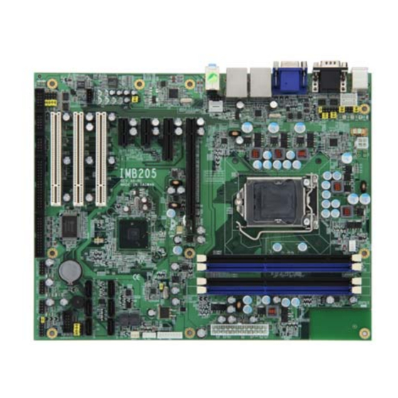
IMB205
www.enochsystems.com
1-877-722-1116
sales@enochsystems.com
Copyright © 2013 Enoch Systems, LLC, Enoch Systems and the Enoch Systems logo are trademarks or registered trademarks of Enoch Systems, LLC and/or its affiliates in the U.S. and other countries.
Third-party trademarks mentioned are the property of their respective owners. All rights reserved.
Advertisement
Table of Contents

Related Manuals for AXIOMTEK IMB205


Summary of Contents for AXIOMTEK IMB205
- Page 1 Product User Manual and enterprise branch and head offices IMB205 www.enochsystems.com 1-877-722-1116 sales@enochsystems.com Copyright © 2013 Enoch Systems, LLC, Enoch Systems and the Enoch Systems logo are trademarks or registered trademarks of Enoch Systems, LLC and/or its affiliates in the U.S. and other countries.
- Page 2 IMB205 Series ™ ™ ® Intel Socket 1156 Core i7 / Core i5 / ™ ® Core i3 / Pentium Processor ATX Industrial Motheroard User’s Manual...
- Page 3 Axiomtek does not make any commitment to update the information in this manual. Axiomtek reserves the right to change or revise this document and/or product at any time without notice. No part of this document may be reproduced, stored in a retrieval...
-
Page 4: Esd Precautions
Wear a wrist-grounding strap, available from most electronic component stores, when handling boards and components. Trademarks Acknowledgments Axiomtek is a trademark of Axiomtek Co., Ltd. ® Windows is a trademark of Microsoft Corporation. AMI is a trademark of American Megatrend Inc. -
Page 5: Table Of Contents
Table of Contents Disclaimers .................... ii ESD Precautions .................. iii CHAPTER 1....................1 INTRODUCTION ..................1 1.1 Specifications..............2 1.2 Utilities Supported ............. 4 CHAPTER 2....................5 JUMPERS AND CONNECTORS..............5 2.1 Board Dimensions ............. 5 2.2 Board Layout..............6 2.3 ... - Page 6 2.4.22 Internal power Connector: CN40 ........31 2.4.23 SMBUS Connector: CN41 ..........31 2.4.24 PCI Slots ................31 2.4.25 PCI Express x1, x4 Slots ..........31 2.4.26 PCI Express x16 Slot ............32 CHAPTER 3....................33 HARDWARE INSTALLATION..............33 3.1 Installing the Processor ..........
- Page 7 FUNCTION ....................86 APPENDIX D .................... 103 ® Intel iAMT SETTINGS ................103 D.1 Entering MEBx ............... 103 D.2 Set & Change Password..........104 ® Intel iAMT Web Console..........106 ...
-
Page 8: Chapter 1
IMB205 LGA1156 ATX Motherboard User’s Manual CHAPTER 1 INTRODUCTION The IMB205 ATX industrial Motherboard supports LGA1156 socket ® ™ ™ ™ ® for Intel Core i7 / Core i5 / Core i3 / Pentium processors with 32/45nm technology .The board integrates Intel® Q57 that deliver... -
Page 9: Specifications
IMB205 LGA1156 ATX Motherboard User’s Manual Specifications ® ™ ™ ™ ® Intel Core i7 / Core i5 / Core i3 / Pentium processors ® Support Intel Turbo Boost Technology(Note 1) System Chipset ® Intel Q57 Express Chipset CPU Socket... - Page 10 IMB205 LGA1156 ATX Motherboard User’s Manual USB Interface Tweleve USB ports (four on the Rear I/O, eight ports by 2x5-pin 2.54 pin-header) Onboard Graphics ® Intel Clarkdale integrated Graphics Processing Unit (GPU) processors which goes with Intel® Q57 chipset with VGA,DisplayPort out(Note 2) ®...
-
Page 11: Utilities Supported
IMB205 LGA1156 ATX Motherboard User’s Manual Watchdog Timer Reset Supported (1-255 levels) NOTE 1. Intel support Turbo Boost Technology depends on the CPU types. 2. When use the onboard DisplayPort and D-Sub ports, you must install an Intel CPU with integrated graphics. -
Page 12: Chapter 2
IMB205 LGA1156 ATX Motherboard User’s Manual CHAPTER 2 JUMPERS AND CONNECTORS Board Dimensions Jumpers and Connectors... -
Page 13: Board Layout
IMB205 LGA1156 ATX Motherboard User’s Manual Board Layout I/O Bracket Jumpers and Connectors... -
Page 14: Jumper Settings
IMB205 LGA1156 ATX Motherboard User’s Manual Jumper Settings Before applying the power to IMB205 Series, please make sure all jumper settings are defaulted as the following table: JUMPER DEFAULT SETTING CN16 Pin 1: DCD Short 7-9 COM4 Mode Select CN16 Pin 8: RI... -
Page 15: Com1 Mode Select Jumpers For Rs-232/422/485 (Jp4, Jp7, Jp8)
IMB205 LGA1156 ATX Motherboard User’s Manual 2.3.1 COM1 Mode Select Jumpers for RS-232/422/485 (JP4, JP7, JP8) These jumpers select the COM1 port’s communication mode to operate RS-232 or RS-422/485. Description Function Jumper Setting COM1 RS-232 (Default) RS-422 RS-485 Jumpers and Connectors... -
Page 16: Com1~Com4 Mode Select Jumpers (Jp1, Jp2, Jp5, Jp6)
IMB205 LGA1156 ATX Motherboard User’s Manual 2.3.2 COM1~COM4 Mode Select Jumpers (JP1, JP2, JP5, JP6) These jumpers select the COM1~COM4 ports’ pin-1 to operate DCD with +5V and +12V power, and pin-8 or pin-9 to operate RI with +5V and +12V. - Page 17 IMB205 LGA1156 ATX Motherboard User’s Manual Description Function Jumper Setting Pin 1=12V COM2 (CN3B) Pin 1=5V *Pin 1=DCD (Default) Pin 9=12V Pin 9=5V *Pin 9=RI (Default) Jumpers and Connectors...
- Page 18 IMB205 LGA1156 ATX Motherboard User’s Manual Description Function Jumper Setting Pin 1=12V COM3 (CN12) Pin 1=5V *Pin 1=DCD (Default) Pin 8=12V Pin 8=5V *Pin 8=RI (Default) Jumpers and Connectors...
- Page 19 IMB205 LGA1156 ATX Motherboard User’s Manual Description Function Jumper Setting Pin 1=12V COM4 (CN16) Pin 1=5V *Pin 1=DCD (Default) Pin 8=12V Pin 8=5V *Pin 8=RI (Default) Jumpers and Connectors...
-
Page 20: Audio Output Select Jumper (Jp3)
IMB205 LGA1156 ATX Motherboard User’s Manual 2.3.3 Audio Output Select Jumper (JP3) This jumper makes the selection of Audio output. Description Function Jumper Setting Line Out Audio Output (Default) Selection Speak Out(w/ Amplifier) Jumpers and Connectors... -
Page 21: Cmos Clear Jumper (Jp12)
IMB205 LGA1156 ATX Motherboard User’s Manual 2.3.4 CMOS Clear Jumper (JP12) You may need to use this jumper is to clear the CMOS memory if incorrect BIOS settings. Description Function Jumper Setting Normal JP12 CMOS Clear (Default) Clear CMOS JP12... -
Page 22: Connectors
IMB205 LGA1156 ATX Motherboard User’s Manual 2.4 Connectors Connectors connect this board with other parts of the system. Loose or improper connection might cause problems. Make sure all connectors are properly and firmly connected. Connector Label Connector Label CN21 Display Port... -
Page 23: Displayport Connector (Cn1)
IMB205 LGA1156 ATX Motherboard User’s Manual 2.4.1 DisplayPort Connector (CN1) DisplayPort is a digital display interface standard. This connector is used to connect a monitor with DisplayPort inputs. Signal LANE 0 LANE 0# LANE 1 LANE 1# LANE 2 LANE 2#... -
Page 24: Ps/2 Keyboard/Mouse Connector (Cn2)
IMB205 LGA1156 ATX Motherboard User’s Manual 2.4.2 PS/2 Keyboard/Mouse Connector (CN2) The board supports a keyboard and Mouse interface. Signal Signal K/B Data M/S Data K/B CLK M/S CLK Jumpers and Connectors... -
Page 25: Com1/2 Connector (Cn3)
IMB205 LGA1156 ATX Motherboard User’s Manual 2.4.3 COM1/2 Connector (CN3) CN3 is a double deck D-Sub connector. The upper CN3A is a standard 9-pin DB9 connector for the Serial Port1 RS-232(COM1), jumper selectable with the +5V/12V power capability is on DCD and RI, depending on the jumper setting. -
Page 26: Vga Connector (Cn4)
IMB205 LGA1156 ATX Motherboard User’s Manual 2.4.4 VGA Connector (CN4) The board supports CRT/ VGA with a 15-pin D-Sub connector for the CRT VGA display. Signal Green Blue DDC DATA Horizontal Sync Vertical Sync DDC CLK 2.4.5 High Definition Audio Jack Connector (CN5) After installing onboard audio driver, you may connect speaker to Line Out jack, microphone to MIC in jack. -
Page 27: Ethernet With Usb Connectors (Cn6, Cn7)
IMB205 LGA1156 ATX Motherboard User’s Manual 2.4.6 Ethernet with USB Connectors (CN6, CN7) The board is equipped with two high performance Plug and Play Ethernet interface fully compliant with the IEEE 802.3 standard. To connect the board to 10-Base-T, 100-Base-T or 1000 Base-T hub, just plug one end of cable to the Ethernet connector and connect the other end (phone jack) to a 10-Base-T, 100-Base-T or 1000 Base-T hub. - Page 28 IMB205 LGA1156 ATX Motherboard User’s Manual LAN LED Description Indication CN6A/CN7A Activity Link LED OFF : No Link Blinking : Data Activity Speed LED OFF :10 Mbps data rate Green : 100 Mbps data rate Orange : 1G Mbps data rate...
-
Page 29: Audio Cd-In Connector: Cn9
IMB205 LGA1156 ATX Motherboard User’s Manual 2.4.7 Audio CD-In Connector: CN9 This connector is provided for external audio input. Description CD IN_L CD IN_R 2.4.8 Internal Mouse Connector (CN10) The board provides the Internal Mouse interface with a 5-pin connector... -
Page 30: Com3/Com4 Connectors (Cn12, Cn16)
IMB205 LGA1156 ATX Motherboard User’s Manual 2.4.10 COM3/COM4 Connectors (CN12, CN16) The board has the onboard serial ports COM3, 4 (CN12, CN16), two 2x5-pin 2.54 pitch box-header to support RS-232. Signal Signal Data Carrier Detect Data Set Ready (DSR) (DCD) -
Page 31: Digital I/O Port (Dio) Connector (Cn20)
IMB205 LGA1156 ATX Motherboard User’s Manual 2.4.12 Digital I/O Port (DIO) Connector (CN20) The board is equipped an 8-channel digital I/O connector CN20 that meets requirements for a system customary automation control. The digital I/O can be configured to control cash drawers, sense warning signals from an Uninterrupted Power System (UPS), or perform store security control. -
Page 32: Floppy Disk Port Connector (Cn24)
IMB205 LGA1156 ATX Motherboard User’s Manual 2.4.14 Floppy Disk Port Connector (CN24) The board provides a 34-pin header type connector CN24 supporting floppy drives. The floppy drives may be any one of the following types: 5.25" 360KB/1.2MB and 3.5" 720KB/1.44MB/2.88MB. -
Page 33: Print Port Connector (Cn25)
IMB205 LGA1156 ATX Motherboard User’s Manual 2.4.15 Print Port Connector (CN25) Print Port Connector This board has a multi-mode parallel port to support the following modes: 1. Standard Mode ™ IBM PC/XT, PC/AT and PS/2 are compatible with bi-directional parallel port. -
Page 34: Cpu Fan Connector (Cn26)
IMB205 LGA1156 ATX Motherboard User’s Manual 2.4.16 CPU Fan Connector (CN26) A CPU fan is always needed for cooling CPU heat. The CPU fan connector provides power to the CPU fan. Signal CN26 +12V Rotation Detection Speed Control Jumpers and Connectors... -
Page 35: Usb Connectors (Cn27, Cn28, Cn31, Cn34)
IMB205 LGA1156 ATX Motherboard User’s Manual 2.4.17 USB Connectors (CN27, CN28, CN31, CN34) The 10-pin standard Universal Serial Bus (USB) connectors, CN27/29/33/45, on this board are for installing versatile USB interface peripherals. Signal Signal USB +5V USB +5V CN34 USB D0-... -
Page 36: Front Panel Connector (Cn35)
8 (+) and pin 2 (-). ATX Power On/Off Button This 2-pin connector, designated at Pins 9 and 10 of CN35, connects the power button of the front panel to the IMB205 - allowing user to control the power on/off state of the power supply. -
Page 37: Atx Power Connector (Cn36)
IMB205 LGA1156 ATX Motherboard User’s Manual 2.4.20 ATX Power Connector (CN36) Steady and sufficient power can be supplied to all components on the board by connecting the power connector. Please make sure all components and devices are properly installed before connecting the power connector. -
Page 38: Internal Power Connector: Cn40
IMB205 LGA1156 ATX Motherboard User’s Manual 2.4.22 Internal power Connector: CN40 This connector CN40 is for support power. Description +12V CN40 -12V 3,3V 5VSB 2.4.23 SMBUS Connector: CN41 This connector CN41 is for SMBUS interface support. Description CN41 SMB_CLOCK SMB_DATA 2.4.24 PCI Slots... -
Page 39: Pci Express X16 Slot
IMB205 LGA1156 ATX Motherboard User’s Manual 2.4.26 PCI Express x16 Slot This motherboard supports PCI Express x16 2.0 graphic cards comply with the PCI Express specifications. Refer to the figure delow for the location of the slots. Jumpers and Connectors... -
Page 40: Chapter 3
IMB205 LGA775 ATX Motherboard User’s Manual CHAPTER 3 HARDWARE INSTALLATION ® Before installing the processor, please access Intel website for more detailed information http://www.intel.com . Installing the Processor NOTE Before installing the CPU, make sure to turn off the computer and unplug the power cord from the power outlet to prevent damage to the CPU. - Page 41 IMB205 LGA1156 ATX Motherboard User’s Manual Introduction to LGA1156 CPU socket Locate the alignment keys on the motherboard CPU socket. Hardware Installation...
- Page 42 IMB205 LGA775 ATX Motherboard User’s Manual Locate the LGA1156 CPU socket on the motherboard. Follow the steps below to correctly install the CPU into the motherboard CPU socket. 1. Press the load lever of LGA1156 CPU socket with your thumb and then move it sideways until it is released from the retention tab, then lift the load lever up.
- Page 43 IMB205 LGA1156 ATX Motherboard User’s Manual 2. Lift the load lever in the direction of the arrow until load plate is completely lifted. 3. Remove the protective cap from the CPU socket. The cap is used to protect the CPU socket against dust and harmful particles.
- Page 44 IMB205 LGA775 ATX Motherboard User’s Manual 4. Be careful not touch pin-pad of CPU and pin of CPU socket. 5. Insert the CPU into the CPU socket. The yellow triangular mark on the CPU must align with the bottom left corner of the CPU socket.
-
Page 45: Installing The Heatsink And Fan
IMB205 LGA1156 ATX Motherboard User’s Manual 6. Close the load plate, and then push down the load lever, ensuring that the front edge of the load plate slides under the shoulder screw(1), insert the load lever under the retention tab(2). - Page 46 IMB205 LGA775 ATX Motherboard User’s Manual 1. Place the heatsink on top of the installed CPU, ensuring that the four fasteners match the holds on the motherboard. 2. Push down two fasteners at a time in a diagonal sequence to secure the heatsink and fan assembly in place.
-
Page 47: Uninstalling The Heatsink And Fan
IMB205 LGA1156 ATX Motherboard User’s Manual 3. Make sure the CPU fan cable is plugged to the CPU fan connector (CN26) on the motherboard. 3.1.2 Uninstalling the heatsink and fan Disconnect the CPU fan cable from the CPU fan connector (CN26) on the motherboard then rotate each fastener counterclockwise. - Page 48 IMB205 LGA775 ATX Motherboard User’s Manual 1. Pull up two fasteners at a time in a diagonal sequence to disengage the heatsink and fan assembly from the motherboard. 2. Remove the heatsink and fan assembly from the motherboard. Hardware Installation...
-
Page 49: Installing The Memory
IMB205 LGA1156 ATX Motherboard User’s Manual Installing the Memory The board supports four 240-pin DDR3 DIMM memory sockets with maximum memory capacity up to 16GB. NOTE A DDR3 module has the same physical dimensions as a DDR2 DIMM but is notched differently to prevent installation on a DDR2 DIMM socket. -
Page 50: Daul Channel Memory Configurtion
IMB205 LGA775 ATX Motherboard User’s Manual 3.2 .1 Daul Channel Memory Configurtion This motherboard provides four DDR3 memory sockets and support Daul Channel Technology. After the memory is installed, the BIOS will automatically detect the specifications and capacity of the memory enabling Dual... - Page 51 IMB205 LGA1156 ATX Motherboard User’s Manual Due to CPU limitations, read the following guidelines before installing the memory in Dual Channel mode. 1. Dual Channel mode cannot be enabled if only one DDR3 memory module is installed. 2. When enabling Dual Channel mode with two or four memory modules, it is recommended that memory of the same capacity, brand, speed, and chips are used for optimum performance.
-
Page 52: Chapter 4
Make sure all correct settings are arranged for your installed microprocessor to prevent the CPU from damages. BIOS The IMB205 Series uses AMI Plug and Play BIOS with a single 64Mbit SPI Flash. System Memory The IMB205 Series supports four 240-pin DDR3 DIMM sockets for a maximum memory of 16GB DDR3 SDRAMs. -
Page 53: I/O Port Address Map
IMB205 LGA1156 ATX Motherboard User’s Manual 4.4 I/O Port Address Map ® ™ ™ ™ ® Intel Core i7 / Core i5 / Core i3 / Pentium processors can communicate via I/O ports. There are total 1KB port addresses available for assignment to other devices via I/O expansion cards. -
Page 54: Interrupt Controller (Irq) Map
IMB205 LGA775 ATX Motherboard User’s Manual 4.5 Interrupt Controller (IRQ) Map The IMB205 Series is a 100% PC compatible control board. It consists of 16 interrupt request lines, and four out of them can be programmable. The mapping list of the 16 interrupt request lines is shown as the following table. -
Page 55: Chapter 5
IMB205 LGA1156 ATX Motherboard User’s Manual CHAPTER 5 AMI BIOS SETUP UTILITY This chapter provides users with detailed description how to set up basic system configuration through the AMIBIOS8 BIOS setup utility. Starting To enter the setup screens, follow the steps below: Turn on the computer and press the <Del>... - Page 56 IMB205 LGA1156 ATX Motherboard User’s Manual The Left <Arrow> keys allow you to select a setup Left/Right screen. The Up and Down <Arrow> keys allow you to select a Up/Down setup screen or sub-screen. The Plus and Minus <Arrow> keys allow you to change +−...
-
Page 57: Main Menu
IMB205 LGA1156 ATX Motherboard User’s Manual Main Menu When you first enter the Setup Utility, you will enter the Main setup screen. You can always return to the Main setup screen by selecting the Main tab. There are two Main Setup options. They are described in this section. -
Page 58: Advanced Menu
IMB205 LGA1156 ATX Motherboard User’s Manual Advanced Menu The Advanced menu allows users to set configuration of the CPU and other system devices. You can select any of the items in the left frame of the screen to go to the sub menus:... - Page 59 IMB205 LGA1156 ATX Motherboard User’s Manual AMI Bios Setup Utility...
- Page 60 IMB205 LGA1156 ATX Motherboard User’s Manual CPU Configuration This screen shows the CPU Configuration, and you can change the value of the selected option. Hardware Prefetcher You can let the processor fetches data and instructions from the memory into the caches that are likely to be required in the near future.
- Page 61 IMB205 LGA1156 ATX Motherboard User’s Manual IDE Configuration You can use this screen to select options for the IDE Configuration, and change the value of the selected option. A description of the selected item appears on the right side of the screen. For items marked with “...
- Page 62 IMB205 LGA1156 ATX Motherboard User’s Manual Third IDE Master Select one of the hard disk drives to configure IDE devices installed in the system by pressing <Enter> for more options. Fourth IDE Master Select one of the hard disk drives to configure IDE devices installed in the system by pressing <Enter>...
- Page 63 IMB205 LGA1156 ATX Motherboard User’s Manual SuperIO Configuration You can use this screen to select options for the SuperIO Configuration, and change the value of the selected option. A description of the selected item appears on the right side of the screen.
- Page 64 IMB205 LGA1156 ATX Motherboard User’s Manual Serial Port4 Address This option specifies the base I/O port address and Default setting is 2E8 Parallel Port Address This item allows you to determine the I/O address for onboard parallel port. There are several options for your selection.
- Page 65 IMB205 LGA1156 ATX Motherboard User’s Manual Hardware Health Configuration This screen shows the Hardware Health Configuration, and a description of the selected item appears on the right side of the screen. H/W Health Configuration This screen displays the temperature of CPU and System, Fan Speed, Vcore, etc.
- Page 66 IMB205 LGA1156 ATX Motherboard User’s Manual ACPI Configuration You can use this screen to select options for the ACPI Configuration, and change the value of the selected option. A description of the selected item appears on the right side of the screen.
- Page 67 IMB205 LGA1156 ATX Motherboard User’s Manual Advanced ACPI Configuration Scroll to this item and press <Enter> to view the Advanced ACPI Configuration sub menu, which contains Advanced ACPI (Advanced Configuration and Power Management Interface) options for your configuration. Advanced ACPI Configuration/ACPI Version Features Allow you to select Version for the Advanced Configuration and Power Interface (ACPI).
- Page 68 IMB205 LGA1156 ATX Motherboard User’s Manual AHCI Configuration You can use this screen to select options for the AHCI Configuration, and change the value of the selected option. A description of the selected item appears on the right side of the screen.
- Page 69 IMB205 LGA1156 ATX Motherboard User’s Manual Intel AMT Configuration You can use this screen to select options for the Intel AMT Configuration, and change the value of the selected option. A description of the selected item appears on the right side of the screen.
- Page 70 IMB205 LGA1156 ATX Motherboard User’s Manual Intel VT-d Configuration You can use this screen to select options for the Intel VT-d Configuration, and change the value of the selected option. A description of the selected item appears on the right side of the screen.
- Page 71 IMB205 LGA1156 ATX Motherboard User’s Manual Remote Access Configuration You can use this screen to select options for the Remote Access Configuration, and change the value of the selected option. A description of the selected item appears on the right side of the screen.
- Page 72 IMB205 LGA1156 ATX Motherboard User’s Manual PCI Express Configuration This screen shows the PCI Express Configuration, and you can change its value. A description of the selected item appears on the right side of the screen. Active State Power-Management Use this item to enable or disable the function of Active State Power-Management to provide you with lower power consumption.
- Page 73 IMB205 LGA1156 ATX Motherboard User’s Manual Trusted Computing You can use this screen to select options for the Trusted Computing, and change the value of the selected option. A description of the selected item appears on the right side of the screen.
- Page 74 IMB205 LGA1156 ATX Motherboard User’s Manual USB Configuration You can use this screen to select options for the USB Configuration, and change the value of the selected option. A description of the selected item appears on the right side of the screen.
-
Page 75: Pci Pnp Menu
IMB205 LGA1156 ATX Motherboard User’s Manual PCI PnP Menu The PCI PnP menu allows users to change the advanced settings for PCI/PnP devices. Clear NVRAM Use this item to clear the data in the NVRAM (CMOS). Here are the options for your selection, No and Yes. - Page 76 IMB205 LGA1156 ATX Motherboard User’s Manual PCI Latency Timer This item controls how long a PCI device can hold the PCI bus before another takes over. The longer the latency, the longer the PCI device can retain control of the bus before handing it over to another PCI device.
-
Page 77: Boot Menu
IMB205 LGA1156 ATX Motherboard User’s Manual Boot Menu The Boot menu allows users to change boot options of the system. You can select any of the items in the left frame of the screen to go to the sub menus:... - Page 78 IMB205 LGA1156 ATX Motherboard User’s Manual Boot Settings Configuration Quick Boot Enabling this item lets the BIOS skip certain tests while booting. The default setting is Enabled. AddOn ROM Display Mode This item selects the display mode for option ROM. The default setting is Force BIOS.
- Page 79 IMB205 LGA1156 ATX Motherboard User’s Manual Wait For ‘F1’ Of Error If this item is enabled, the system waits for the F1 key to be pressed when error occurs. The default setting is Enabled. Hit ‘DEL’ Message Display If this item is enabled, the system displays the message “Press DEL to run Setup”...
-
Page 80: Security Menu
IMB205 LGA1156 ATX Motherboard User’s Manual Security Menu The Security menu allows users to change the security settings for the system. Supervisor Password This item indicates whether a supervisor password has been set. If the password has been installed, Installed displays. -
Page 81: Chipset Menu
IMB205 LGA1156 ATX Motherboard User’s Manual Chipset Menu The Chipset menu allows users to change the advanced chipset settings. You can select any of the items in the left frame of the screen to go to the sub menus: North Bridge Configuration... - Page 82 IMB205 LGA1156 ATX Motherboard User’s Manual North Bridge Configuration Memory Remap Feature Use this item to enable or disable the remapping of the overlapped PCI memory above the total physical memory. Only 64-bit OS supports this function. DRAM Frequency This item allows you to control the Memory Clock.
- Page 83 IMB205 LGA1156 ATX Motherboard User’s Manual Memory Hole You can reserve this area of system memory for ISA adapter ROM. When this area is reserved it cannot be cached. Check the user information of peripherals that need to use this area o f system memory for the memory requirements.
- Page 84 IMB205 LGA1156 ATX Motherboard User’s Manual South Bridge Configuration USB Functions This item allows you to enabled or disabled USB functions. GbE LAN Boot This item allows you to enabled or disabled Intel® WG82578DM LAN Boot ROM. GbE Wake Up From S5 This item specifies whether the system will be awakened from the S5 power.
- Page 85 IMB205 LGA1156 ATX Motherboard User’s Manual Restore on AC Power Loss This item can control how the PC will behave once power is restored following a power outage, or other unexpected shutdown. AMI Bios Setup Utility...
- Page 86 IMB205 LGA1156 ATX Motherboard User’s Manual ME Subsystem Configuration It is strongly recommended that you do not modify these options unless you are an advanced user. ME HECI Configuration/ME-HECI Host Embedded Communication Interface (HECI) provides an interface for the exchange of message between the host software and the ME firmware.
- Page 87 IMB205 LGA1156 ATX Motherboard User’s Manual ME HECI Configuration/ME-KT When set to [Enabled], the KT function helps redirect keyboard and POST message to the remote management console and thus facilitates the control of the client machine through the network. Here are the options for your selection, Disabled and Enabled.
-
Page 88: Exit Menu
IMB205 LGA1156 ATX Motherboard User’s Manual Exit Menu The Exit menu allows users to load your system configuration with optimal or failsafe default values. Save Changes and Exit When you have completed the system configuration changes, select this option to leave Setup and reboot the computer so the new system configuration parameters can take effect. - Page 89 IMB205 LGA1156 ATX Motherboard User’s Manual Load Optimal Defaults It automatically sets all Setup options to a complete set of default settings when you select this option. The Optimal settings are designed for maximum system performance, but may not work best for all computer applications. In particular, do not use the Optimal Setup options if your computer is experiencing system configuration problems.
-
Page 90: Watchdog Timer
IMB205 LGA1156 ATX Motherboard User’s Manual APPENDIX A WATCHDOG TIMER Watchdog Timer Setting After the system stops working for a while, it can be auto-reset by the Watchdog Timer. The integrated Watchdog Timer can be set up in the system reset mode by program. - Page 91 IMB205 LGA1156 ATX Motherboard User’s Manual Timeout Value Range 1 to 255 Minute / Second Program Example 2E, 87 2E, 87 2E, 07 Logical Device 8 2F, 08 2E, 30 Activate 2F, 01 2E, F5 Set Minute or Second 2F, N...
-
Page 92: Digital I/O
IMB205 LGA1156 ATX Motherboard User’s Manual APPENDIX B Digital I/O Using the Digital Output Function O 2E 87 O 2E 87 O 2E 07 O 2F 08 O 2E 30 O 2F 02 Setting DIO is active O 2E E0... -
Page 93: Configuring Sata For Raid
IMB205 LGA1156 ATX Motherboard User’s Manual APPENDIX C CONFIGURING SATA FOR RAID FUNCTION Configuring SATA Hard Drive(s) for RAID Function Please follow up the steps below to configure SATA hard drive(s): (1) Install SATA hard drive(s) in your system. (2) Enter the BIOS Setup to configure SATA controller mode and boot sequence. - Page 94 IMB205 LGA1156 ATX Motherboard User’s Manual (2)-1-1 Turn on your system, and then press the Del button to enter BIOS Setup during running POST (Power-On Self Test). If you want to create RAID, just go to the Advanced Settings menu/IDE configuration, select the Configure SATA as, and press <Enter>...
- Page 95 IMB205 LGA1156 ATX Motherboard User’s Manual (2)-1-2 A list of options appears, please select RAID. Configuration SATA for RAID Function...
- Page 96 IMB205 LGA1156 ATX Motherboard User’s Manual (2)-2 Set CDROM for First Boot Device under the Boot Settings menu to boot CD-ROM after system restarts. Configuration SATA for RAID Function...
- Page 97 IMB205 LGA1156 ATX Motherboard User’s Manual (2)-3 Save and exit the BIOS Setup. (3) Configuring RAID by the RAID BIOS Enter the RAID BIOS setup utility to configure a RAID array. Skip this step and proceed to Section 4 if you do not want to create a RAID.
- Page 98 IMB205 LGA1156 ATX Motherboard User’s Manual (3)-2 After you press <CTRL+ I>, the Create RAID Volume screen will appear. If you want to create a RAID array, select the Create RAID Volume option in the Main Menu and press ENTER.
- Page 99 IMB205 LGA1156 ATX Motherboard User’s Manual (3)-3-1 After entering the CREATE VOLUME MENU screen, you can type the disk array name with 1~16 letters (letters cannot be special characters) in the item “Name”. Configuration SATA for RAID Function...
- Page 100 IMB205 LGA1156 ATX Motherboard User’s Manual (3)-3-2 When finished, press ENTER to select a RAID level. There are three RAID levels, RAID0, RAID1 and RAID5 & RAID10. Select a RAID level and press ENTER. Configuration SATA for RAID Function...
- Page 101 IMB205 LGA1156 ATX Motherboard User’s Manual (3)-4 Set the stripe block size. The KB is the standard unit of stripe block size. The stripe block size can be 4KB to 128KB. After the setting, press ENTER for the array capacity.
- Page 102 IMB205 LGA1156 ATX Motherboard User’s Manual (3)-5 After setting all the items on the menu, select Create Volume and press ENTER to start creating the RAID array. Configuration SATA for RAID Function...
- Page 103 IMB205 LGA1156 ATX Motherboard User’s Manual (3)-6 When prompting the confirmation, press “Y“to create this volume, or “N“to cancel the creation. Configuration SATA for RAID Function...
- Page 104 IMB205 LGA1156 ATX Motherboard User’s Manual After the creation is completed, you can see detailed information about the RAID Array in the DISK/VOLUME INFORMATION section, including RAID mode, disk block size, disk name, and disk capacity, etc. Configuration SATA for RAID Function...
- Page 105 IMB205 LGA1156 ATX Motherboard User’s Manual Delete RAID Volume If you want to delete a RAID volume, select the Delete RAID Volume option in Main Menu. Press ENTER and follow on-screen instructions. Please press [ESC] to exit the RAID BIOS utility.
- Page 106 IMB205 LGA1156 ATX Motherboard User’s Manual (4) Making a SATA Driver Disk To install the operating system onto a serial ATA hard disk successfully, you need to install the SATA controller driver during the OS installation. Without the driver, the hard disk may not be recognized during the Windows setup process.
- Page 107 IMB205 LGA1156 ATX Motherboard User’s Manual (5) Installing the SATA controller driver during the OS installation Now, the SATA driver disk is ready, and BIOS settings configured, you can proceed to install Windows 2000/XP onto your SATA hard drive using the SATA driver. Here is an example for Windows XP installation.
- Page 108 IMB205 LGA1156 ATX Motherboard User’s Manual (5)-2 When you see the screen below, insert the floppy disk containing the SATA driver and press “S”. Configuration SATA for RAID Function...
- Page 109 IMB205 LGA1156 ATX Motherboard User’s Manual (5)-3 If the Setup correctly recognizes the driver of the floppy disk, a controller menu will appear below. Use the ARROW keys to select Intel® ICH8R/ICH9R/ICH10R/DO/PCH SATA RAID Controller and press ENTER. Then it will begin to load the SATA driver from the floppy disk.
-
Page 110: Intel Iamt Settings
IMB205 LGA1156 ATX Motherboard User’s Manual APPENDIX D Intel iAMT SETTINGS ® ® ® The Intel Active Management Technology (Intel iAMT) has decreased a major barrier to IT efficiency that uses built-in platform capabilities and popular third-party management and security applications to allow IT a better discovering, healing, and protection their networked computing assets. -
Page 111: Set & Change Password
IMB205 LGA1156 ATX Motherboard User’s Manual D.2 Set & Change Password 1. You will be asked to set a password when first log in. The default password is ‘admin’. INTEL AMT Setting... - Page 112 IMB205 LGA1156 ATX Motherboard User’s Manual 2. You will be asked to change the password before setting ME. 3. You must confirm your new password while revising. The new password must contain: (example:!!11qqQQ) (default value) Eight characters One upper case...
-
Page 113: Intel Iamt Web Console
IMB205 LGA1156 ATX Motherboard User’s Manual ® D.3 Intel iAMT Web Console From a web browser, please type http ://( IP ADDRESS):16992, ® which connects to Intel iAMT Web. Example: http://10.1.40.214:16992 To log on, you will be required to type in username and password for access to the Web. - Page 114 IMB205 LGA1156 ATX Motherboard User’s Manual Enter the iAMT Web. Click Remote Control, and select commands on the right side. 5. When you have finished using the iAMT Web console, close the Web browser. INTEL AMT Setting...
Need help?
Do you have a question about the IMB205 and is the answer not in the manual?
Questions and answers