
Related Manuals for AXIOMTEK imb500


Summary of Contents for AXIOMTEK imb500
- Page 1 IMB500 ® Intel Socket 1151 Core i7/ i5/ i3 Processors ATX Industrial Motherboard User’s Manual...
- Page 2 Axiomtek does not make any commitment to update the information in this manual. Axiomtek reserves the right to change or revise this document and/or product at any time without notice. No part of this document may be reproduced, stored in a retrieval system, or transmitted, in any form or by any means, electronic, mechanical, photocopying, recording, or otherwise, without the prior written permission of Axiomtek Co., Ltd.
-
Page 3: Esd Precautions
It discharges static electricity from your body. Wear a wrist-grounding strap, available from most electronic component stores, when handling boards and components. Trademarks Acknowledgments Axiomtek is a trademark of Axiomtek Co., Ltd. ® ® Intel and Celeron are trademarks of Intel Corporation. -
Page 4: Table Of Contents
Table of Contents Disclaimers ...................... ii ESD Precautions ..................... iii Chapter 1 Introduction ..........1 Features ....................2 Specifications ..................2 Chapter 2 Board and Pin Assignments ....5 Board Layout ..................5 Rear I/O ....................6 Jumper Settings ..................7 2.3.1 Clear CMOS (JP1) .................. - Page 5 Chapter 3 Hardware Description ......23 Microprocessors .................. 23 BIOS....................23 System Memory .................. 23 Chapter 4 AMI BIOS Setup Utility ......25 Starting ....................25 Navigation Keys .................. 25 Main Menu ..................27 Advanced Menu .................. 28 Chipset Menu ..................41 Security Menu ..................
- Page 6 This page is intentionally left blank.
-
Page 7: Chapter 1 Introduction
IMB500 LGA1151 ATX Motherboard Chapter 1 Introduction ® The IMB500 is an advanced ATX industrial motherboard based on the 6 Generation Intel ® ® ® Core™ i7/ i5/ i3/ Pentium and Celeron processors (Skylake) in LGA1151 Socket with Intel Q170. The optimized IMB500 is specially designed for better computing and visual performance;... -
Page 8: Features
IMB500 LGA1151 ATX Motherboard Features ® ® ® LGA1151 Socket 6 Generation Intel Core™ i7/ i5/ i3, Pentium and Celeron processors (Skylake) 4 DDR4 2133/1866MHz DIMM with maximum capacity up to 64GB(max. 16GB per slot ) DisplayPort, HDMI, and VGA with triple view supported ... - Page 9 IMB500 LGA1151 ATX Motherboard Display One 15-pin D-Sub as VGA connector. Resolution max. up to 1920x1200 @60Hz. One HDMI 1.4b with resolution max. up to 4096x2160 @24Hz. One DisplayPort with resolution max. up to 4096x2304 @60Hz.
- Page 10 IMB500 LGA1151 ATX Motherboard This page is intentionally left blank. Introduction...
-
Page 11: Board And Pin Assignments
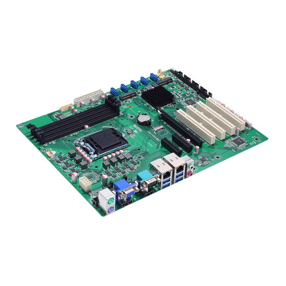
IMB500 LGA1151 ATX Motherboard Chapter 2 Board and Pin Assignments Board Layout Board and Pin Assignments... -
Page 12: Rear I/O
IMB500 LGA1151 ATX Motherboard Rear I/O Jumpers/Headers/Connectors Internal USB Headers (CN21~CN24) PCI Slots (CN35~CN38) GPIO Header (CN6) mSATA Slot (CN4) Debug Header SATA 3.0 Connectors (CN26~CN30) COM3~COM6 Headers (CN15~CN18) PCI-Express Mini Card Connector (CN3) AT/ATX Mode Select Jumper (JP2) ATX1 Power Input Connector (CN34) -
Page 13: Jumper Settings
And remove jumper clip from 2 jumper pins to open. The following illustration shows how to set up jumper. Before applying power to IMB500 Series, please make sure all of the jumpers are in factory default position. Below you can find a summary table of all jumpers and onboard default settings. -
Page 14: Clear Cmos (Jp1)
IMB500 LGA1151 ATX Motherboard Jumper Description Setting Clear CMOS 1-2 Close Default: Normal Operation AT/ATX Power Mode Select 1-2 Close Default: ATX Mode JP3/7 1-2 Close COM1/2 RS-232/422/485 Mode Select JP5/9 3-5, 4-6 Close Default: RS-232 JP6/10 3-5, 4-6 Close... -
Page 15: Com1 Mode Select (Jp3, Jp5, Jp6)
IMB500 LGA1151 ATX Motherboard 2.3.3 COM1 Mode Select (JP3, JP5, JP6) Use these jumpers (3x2-pin p=2.54mm) to set COM1 port to operate in RS-232, RS-422 or RS-485 communication mode. Function Setting JP3 1-2 close RS-232 mode JP5 3-5, 4-6 close... -
Page 16: Connectors
IMB500 LGA1151 ATX Motherboard Connectors Signals go to other parts of the system through connectors. Loose or improper connection might cause problems, please make sure all connectors are properly and firmly connected. Here is a summary table showing connectors on the hardware. -
Page 17: Displayport Connector (Cn2)
IMB500 LGA1151 ATX Motherboard 2.4.1 DisplayPort Connector (CN2) The DisplayPort interface is available through CN2. Signal Signal DP_TX0+ DP_TX0- DP_TX1+ DP_TX1- DP_TX2+ DP_TX2- DP_TX3+ DP_TX3- DP_AUX+ DP_AUX- DP_HPD +3.3V 2.4.2 PCI-Express Mini Card Connector (CN3) The CN3 complies with PCI-Express Mini Card Spec. V1.2. -
Page 18: Msata Slot (Cn4)
IMB500 LGA1151 ATX Motherboard 2.4.3 mSATA Slot (CN4) Signal Signal +3.3V_DUAL +1.5V BUF_PLT_RST_N SATA0_RX_DP +3.3V_DUAL SATA0_RX_DN +1.5V SMB_CLK_RESUME SATA0_TX_DN SMB_DATA_RESUME SATA0_TX_DP USB9- USB9+ +3.3V_DUAL +3.3V_DUAL +1.5V +3.3V_DUAL NOTE: screw type is M2*0.4 Board and Pin Assignments... -
Page 19: Front Panel Header (Cn5)
IMB500 LGA1151 ATX Motherboard 2.4.4 Front Panel Header (CN5) This is front panel header (7x2-pin p=2.54mm). Signal Power LED+ SPK- BUZZER Power LED- SPK+ PWR- PWR+ RESET- RESET+ HD LED- HD LED+ : The buzzer on motherboard will be active when pin 2 and pin 4 is connected;... -
Page 20: Ps/2 Keyboard And Mouse Connector (Cn8)
IMB500 LGA1151 ATX Motherboard 2.4.6 PS/2 Keyboard and Mouse Connector (CN8) The motherboard has two 6-pin mini-DIN PS/2 connectors on the rear I/O; green for mouse and purple for keyboard. Signal Signal KB_DT1 MS_DT1 +5V_DUAL +5V_DUAL KB_CK1 MS_CK1 2.4.7 COM Connector (CN9) This is a high rise 9-pin D-Sub connector for COM1 serial port interface. -
Page 21: Lan And Usb 3.0 Connectors (Cn11 And Cn12)
IMB500 LGA1151 ATX Motherboard 2.4.8 LAN and USB 3.0 Connectors (CN11 and CN12) The motherboard comes with two high performance plug and play Ethernet interfaces (RJ-45) which are fully compliant with the IEEE 802.3 standard. Connection can be established by plugging one end of the Ethernet cable into this RJ-45 connector and the other end to a 1000/100/10 Base-T hub. -
Page 22: Front Audio Header (Cn14)
IMB500 LGA1151 ATX Motherboard 2.4.10 Front Audio Header (CN14) This is front audio header (5x2-pin p=2.00mm) for convenient connection and control of audio devices. Signal Signal MIC_IN LINE_IN_L LINE_IN_R AUD_OUT_L AUD_OUT_R 2.4.11 COM Headers (CN15~CN18 and CN44) The motherboard comes with 5x2-pin p=2.54mm headers for COM3~COM6 and COM2 serial port interfaces. -
Page 23: Hdmi Connector (Cn20)
IMB500 LGA1151 ATX Motherboard 2.4.12 HDMI Connector (CN20) The HDMI (High-Definition Multimedia Interface) is a compact digital interface which is capable of transmitting high-definition video and high-resolution audio over a single cable. Signal Signal DATA2+ DATA2- DATA1+ DATA1- DATA0+ DATA0-... -
Page 24: Sata 3.0 Connectors (Cn26~Cn30)
IMB500 LGA1151 ATX Motherboard 2.4.15 SATA 3.0 Connectors (CN26~CN30) These Serial Advanced Technology Attachment (Serial ATA or SATA) connectors are for SATA 3.0 interface allowing up to 6.0Gb/s data transfer rate. It is a computer bus interface for connecting to devices such as hard disk drive. -
Page 25: Power Input Connectors (Cn33 And Cn34)
IMB500 LGA1151 ATX Motherboard 2.4.18 Power Input Connectors (CN33 and CN34) Steady and sufficient power can be supplied to all components on the motherboard by connecting power connector. Please make sure all components and devices are properly installed before connecting the power connector. -
Page 26: Pci-Express X4 Slots (Cn39 And Cn40)
IMB500 LGA1151 ATX Motherboard 2.4.19 PCI-Express x4 Slots (CN39 and CN40) This motherboard has two PCI-Express x4 slots. Signal Signal +12V_PS +12V_PS +12V_PS +12V_PS +12V_PS SMB_CLK_RESUME SMB_DATA_RESUME +3.3V_PS +3.3V_PS +3.3V_SB +3.3V_PS PCH_WAKE_N PWRGD CLKOUT_PCIE_P5 PCIE1_SLOT1_TX_DP_C CLKOUT_PCIE_N5 PCIE1_SLOT1_TX_DN_C PCIE1_SLOT1_RX_DP_C PCIEX4_SLOT1_PRSNT2_N PCIE1_SLOT1_RX_DN_C... -
Page 27: Fan Connectors (Cn41~Cn43)
IMB500 LGA1151 ATX Motherboard 2.4.20 Fan Connectors (CN41~CN43) This motherboard has three fan connectors. Find fan speed option(s) at BIOS Setup Utility: Advanced\HW Monitor\PC Health Status. The CN41 (4x1-pin p=2.54mm) is for CPU fan connector. Signal +12V FAN Speed Detection FAN Speed Control The CN42 and CN43 (4x1-pin p=2.54mm) are for system fan connectors. - Page 28 IMB500 LGA1151 ATX Motherboard This page is intentionally left blank. Board and Pin Assignments...
-
Page 29: Chapter 3 Hardware Description
The IMB500 Series uses AMI Plug and Play BIOS. System Memory The IMB500 supports four 288-pin DDR4 DIMM sockets for maximum memory capacity up to 64GB DDR4 SDRAMs. The memory module comes in sizes of 2GB, 4GB, 8GB and 16GB. - Page 30 IMB500 LGA1151 ATX Motherboard This page is intentionally left blank. Hardware Description...
-
Page 31: Ami Bios Setup Utility
IMB500 LGA1151 ATX Motherboard Chapter 4 AMI BIOS Setup Utility The AMI UEFI BIOS provides users with a built-in setup program to modify basic system configuration. All configured parameters are stored in a flash chip to save the setup information whenever the power is turned off. - Page 32 IMB500 LGA1151 ATX Motherboard Hot Keys Description Left/Right The Left and Right <Arrow> keys allow you to select a setup screen. The Up and Down <Arrow> keys allow you to select a setup screen or sub Up/Down screen.
-
Page 33: Main Menu
IMB500 LGA1151 ATX Motherboard Main Menu When you first enter the setup utility, you will enter the Main setup screen. You can always return to the Main setup screen by selecting the Main tab. System Time/Date can be set up as described below. -
Page 34: Advanced Menu
IMB500 LGA1151 ATX Motherboard Advanced Menu The Advanced menu also allows users to set configuration of the CPU and other system devices. You can select any of the items in the left frame of the screen to go to the sub menus: ►... - Page 35 IMB500 LGA1151 ATX Motherboard Super IO Configuration You can use this screen to select options for the Super IO Configuration, and change the value of the selected option. A description of the selected item appears on the right side of the screen.
- Page 36 IMB500 LGA1151 ATX Motherboard Hardware Monitor This screen monitors hardware health status. This screen displays the temperature of system and CPU, cooling fans speed in RPM and system voltages (VCC_CPU, DDR, +12V, +5V and +3.3V). AMI BIOS Setup Utility...
- Page 37 IMB500 LGA1151 ATX Motherboard Fan Function This screen allows you to select CPU and system fan mode. CPU_Fan1/Smart Fan 2/Smart Fan 3 Mode These items allow you to select CPU and system fans mode, which can be set to Full on, Manual and Automatic Mode.
- Page 38 IMB500 LGA1151 ATX Motherboard ACPI Settings ACPI Sleep State Select the ACPI (Advanced Configuration and Power Interface) sleep state. Configuration options are Suspend Disabled and S3 (Suspend to RAM). The default is S3 (Suspend to RAM); this option selects ACPI sleep state the system will enter when suspend button is pressed.
- Page 39 IMB500 LGA1151 ATX Motherboard Trusted Computing You can use this screen for TPM (Trusted Platform Module) configuration. It also shows current TPM status information. Security Device Support Enable or disable BIOS support for security device. AMI BIOS Setup Utility...
- Page 40 IMB500 LGA1151 ATX Motherboard CPU Configuration This screen shows CPU information, and you can change the value of the selected option. Hyper-threading Enable or disable Hyper-threading Technology, which allows a single physical processor to multitask as multiple logical processors. When disabled, only one thread per enabled core is enabled.
- Page 41 IMB500 LGA1151 ATX Motherboard SATA and RST Configuration During system boot up, the BIOS automatically detects the presence of SATA devices. In the SATA Configuration menu, you can see the currently installed hardware in the SATA ports. SATA Controller(s) Enable or disable the SATA Controller feature.
- Page 42 IMB500 LGA1151 ATX Motherboard PCH-FW Configuration This screen displays ME Firmware information. AMT Configuration Use this screen to configure AMT parameters. AMT BIOS Features Enable or disable Active Management Technology BIOS features. The default is Enabled. AMI BIOS Setup Utility...
- Page 43 IMB500 LGA1151 ATX Motherboard USB Configuration USB Devices Display all detected USB devices. AMI BIOS Setup Utility...
- Page 44 IMB500 LGA1151 ATX Motherboard IT8786 GPIO Configuration You can use this screen to set input/output and high/low for each port. AMI BIOS Setup Utility...
- Page 45 IMB500 LGA1151 ATX Motherboard Serial Port Console Redirection You can use this screen to select options for Serial Port Console Redirection, and change the value of the selected option. A description of the selected item appears on the right side of the screen.
- Page 46 IMB500 LGA1151 ATX Motherboard Utility Configuration BIOS Flash Utility BIOS flash utility configuration. For more detailed information, please refer to Appendix B. AMI BIOS Setup Utility...
-
Page 47: Chipset Menu
IMB500 LGA1151 ATX Motherboard Chipset Menu The Chipset menu allows users to change the advanced chipset settings. You can select any of the items in the left frame of the screen to go to the sub menus: ► System Agent (SA) Configuration ►... - Page 48 IMB500 LGA1151 ATX Motherboard System Agent (SA) Configuration This screen allows users to configure System Agent (SA) parameters. For items marked with “”, please press <Enter> for more options. Graphics Configuration Open sub menu for parameters related to graphics configuration.
- Page 49 IMB500 LGA1151 ATX Motherboard Graphics Configuration Primary IGFX Boot Display Select the video device which will be activated during POST (Power-On Self Test). The default is Auto. AMI BIOS Setup Utility...
- Page 50 IMB500 LGA1151 ATX Motherboard Memory Configuration This screen shows system memory information. PCH-IO Configuration This screen allows you to set PCH parameters. PCH LAN Controller Enable or disable onboard PCH LAN controller. Wake on LAN Enable Enable or disable integrated LAN to wake the system.
-
Page 51: Security Menu
IMB500 LGA1151 ATX Motherboard Security Menu The Security menu allows users to change the security settings for the system. Administrator Password This item indicates whether an administrator password has been set (installed or uninstalled). User Password This item indicates whether a user password has been set (installed or uninstalled). -
Page 52: Boot Menu
IMB500 LGA1151 ATX Motherboard Boot Menu The Boot menu allows users to change boot options of the system. Setup Prompt Timeout Number of seconds to wait for setup activation key. 65535(0xFFFF) means indefinite waiting. Bootup NumLock State Use this item to select the power-on state for the keyboard NumLock. -
Page 53: Save & Exit Menu
IMB500 LGA1151 ATX Motherboard Save & Exit Menu The Save & Exit menu allows users to load your system configuration with optimal or fail-safe default values. Save Changes and Exit When you have completed the system configuration changes, select this option to leave Setup and return to Main Menu. - Page 54 IMB500 LGA1151 ATX Motherboard Discard Changes Select this option to quit Setup without making any permanent changes to the system configuration. Select Discard Changes from the Save & Exit menu and press <Enter>. Select Yes to discard changes. ...
-
Page 55: Appendix A Watchdog Timer
IMB500 LGA1151 ATX Motherboard Appendix A Watchdog Timer About Watchdog Timer Software stability is major issue in most application. Some embedded systems are not watched by human for 24 hours. It is usually too slow to wait for someone to reboot when computer hangs. - Page 56 IMB500 LGA1151 ATX Motherboard This page is intentionally left blank. Watchdog Timer...
-
Page 57: Appendix Bbios Flash Utility
Please read and follow the instructions below carefully. In your USB flash drive, create a new folder and name it “Axiomtek”, see figure below. Copy BIOS ROM file (e.g. IMB500.005) to “Axiomtek” folder. - Page 58 Select the USB drive containing BIOS ROM file you want to update using the <> or <> key. Then press <Enter> to get into “Axiomtek” folder. Now you can see the BIOS ROM file on the screen, press <Enter> to select.
- Page 59 IMB500 LGA1151 ATX Motherboard Please wait while BIOS completes the entire flash update process: erase data, write new data and verify data. 10. When you see the following figure, press <Enter> to finish the update process. After that the system will shut down and restart immediately.
Need help?
Do you have a question about the imb500 and is the answer not in the manual?
Questions and answers