
Related Manuals for AXIOMTEK IMB524


Summary of Contents for AXIOMTEK IMB524
- Page 1 IMB523 / 524 / 525 ® Intel Socket 1151 Core i7/ i5/ i3 / ® ® Pentium / Celeron Processors ATX Industrial Motherboard User’s Manual...
- Page 2 Axiomtek does not make any commitment to update the information in this manual. Axiomtek reserves the right to change or revise this document and/or product at any time without notice. No part of this document may be reproduced, stored in a retrieval system, or transmitted, in any form or by any means, electronic, mechanical, photocopying, recording, or otherwise, without the prior written permission of Axiomtek Co., Ltd.
-
Page 3: Esd Precautions
To discharge static electricity from your body. Wear a grounding wrist strap, available from most electronic component stores, when handling boards and components. Trademarks Acknowledgments Axiomtek is a trademark of Axiomtek Co., Ltd. ® ® Intel and Celeron are trademarks of Intel Corporation. -
Page 4: Table Of Contents
Table of Contents Disclaimers ...................... ii ESD Precautions ..................... iii Chapter 1 Introduction ..........1 Features ....................2 Specifications ..................2 Packing list .................... 4 Chapter 2 Board and Pin Assignments ....5 Board Layout ..................5 Rear I/O ....................7 Block Diagram .................. - Page 5 2.5.21 VGA and DVI-D Connector (CN3) ............. 25 2.5.22 TPM Pin Header (CN23) ................26 2.5.23 Internal Mouse Connector (CN9) .............. 26 2.5.24 Internal Keyboard Connector (CN8) ............26 2.5.25 DIMM Sockets (DIMM1 ~ DIMM4) ............27 Chapter 3 Hardware Description ......29 Microprocessors ..................
- Page 6 This page is intentionally left blank.
-
Page 7: Chapter 1 Introduction
IMB523 / 524 / 525 LGA1151 ATX Motherboard Chapter 1 Introduction The IMB523 / 524 / 525 is an advanced ATX industrial motherboard based on the 8th Generation Intel® Core™ i7/ i5/ i3/ Pentium® and Celeron® processors (Coffeelake) in an LGA1151 socket and comes with an Intel®... -
Page 8: Features
LGA1151 Socket 8 Generation Intel and Celeron processor. Chipset ® Intel Q370. (IMB523) ® Intel H310. (IMB524) ® Intel C246. (IMB525) BIOS AMI BIOS. System Memory Q370: 4 x 288-pin DIMM sockets. - Page 9 IMB523 / 524 / 525 LGA1151 ATX Motherboard USB Interface Q370 / C246: 2 x USB3.1(Gen2) ports. 4 x USB 3.1(Gen1) ports. 7 x USB 2.0 ports. H310: 4 x USB 3.1(Gen1) ports. ...
-
Page 10: 1.3 Packing List
IMB523 / 524 / 525 LGA1151 ATX Motherboard 1.3 Packing list Bulk packing 1 x Motherboard 1 x I/O bracket Gift box 1 x Motherboard 1 x I/O bracket 1 x Driver DVD Introduction... -
Page 11: Board And Pin Assignments
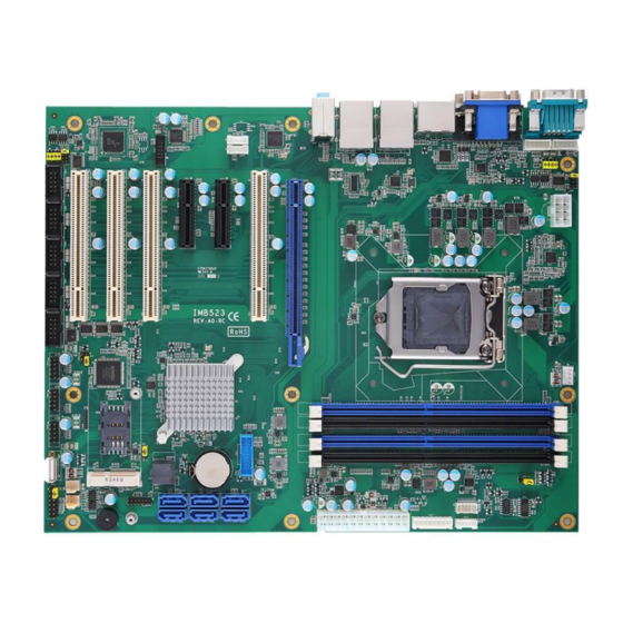
IMB523 / 524 / 525 LGA1151 ATX Motherboard Chapter 2 Board and Pin Assignments Board Layout IMB523 / 525 Top side Board and Pin Assignments... - Page 12 IMB523 / 524 / 525 LGA1151 ATX Motherboard IMB524 Top side Board and Pin Assignments...
-
Page 13: Rear I/O
IMB523 / 524 / 525 LGA1151 ATX Motherboard Rear I/O I/O side I/O bracket Board and Pin Assignments... -
Page 14: Block Diagram
IMB523 / 524 / 525 LGA1151 ATX Motherboard Block Diagram IMB523 / 525 Board and Pin Assignments... - Page 15 IMB523 / 524 / 525 LGA1151 ATX Motherboard IMB524 Board and Pin Assignments...
-
Page 16: Jumper Settings
IMB523 / 524 / 525 LGA1151 ATX Motherboard Jumper Settings Pin description A jumper is a small component consisting of a jumper clip and jumper pins. Install a jumper clip on two jumper pins to close the jumper pins. Remove the jumper clip from two jumper pins to open the jumper pins. -
Page 17: Clear Cmos (Jp8)
IMB523 / 524 / 525 LGA1151 ATX Motherboard 2.4.1 Clear CMOS (JP8) This jumper (3x1-pin p=2.54mm) allows you to clear the Real Time Clock (RTC) RAM in CMOS. You can clear the CMOS memory of date, time, and system setup parameters by erasing the CMOS RTC RAM data. -
Page 18: Com1 Mode Select (Jp4, Jp5, Jp6)
IMB523 / 524 / 525 LGA1151 ATX Motherboard 2.4.3 COM1 Mode Select (JP4, JP5, JP6) Use these jumpers (3x2-pin p=2.54mm) to set COM1 port to operate in RS-232, RS-422 or RS-485 communication mode. Function Setting JP6 1-2 close RS-232 mode JP4 3-5, 4-6 close (Default) JP5 3-5, 4-6 close... -
Page 19: Connectors
IMB523 / 524 / 525 LGA1151 ATX Motherboard Connectors Signals go to other parts of the system through connectors. Loose or improper connection might cause problems, Make sure all connectors are properly and firmly connected. Here is a summary table showing the connectors on the hardware. Connector Description PS/2 KB/MS Connector... -
Page 20: Mini Pci-Express Connector (Cn22) (Optional)
IMB523 / 524 / 525 LGA1151 ATX Motherboard 2.5.1 Mini PCI-Express Connector (CN22) (Optional) Signal Signal WAKE# +3.3V_DUAL +1.5V CLKREQ# UIM_PWR UIM_DATA REFCLK- UIM_CLK REFCLK+ UIM_RESET UIM_VPP W_DISABLE# PERST# PE_RXN7 +3.3V_DUAL PE_RXP7 +1.5V SMB_CLK_RESUME PE_TXN7 SMB_DATA_RESUME PE_TXP7 USB3- USB3+ +3.3V_DUAL +3.3V_DUAL +1.5V +3.3V_DUAL... -
Page 21: Front Panel Header (Cn24)
IMB523 / 524 / 525 LGA1151 ATX Motherboard 2.5.3 Front Panel Header (CN24) This is a front panel header (7x2-pin p=2.54mm). Signal Power LED+ SPK- BUZZER Power LED- SPK+ PWR- PWR+ RESET- RESET+ HD LED- HD LED+ : The buzzer on the motherboard will be active when pin 2 and pin 4 are connected;... -
Page 22: Com1 Connector (Com1)
IMB523 / 524 / 525 LGA1151 ATX Motherboard 2.5.5 COM1 Connector (COM1) This is a high rise 9-pin D-Sub connector for COM1 serial port interface. The pin assignments of RS-232/422/485 are listed in the table below. RS-232 RS-422 RS-485 DCD# 485- 485+ DTR#... -
Page 23: Lan And Usb 3.1 Connectors (Cn5 And Cn6)
IMB523 / 524 / 525 LGA1151 ATX Motherboard 2.5.6 LAN and USB 3.1 Connectors (CN5 and CN6) The motherboard comes with two high performance plug and play Ethernet interfaces (RJ-45) which are fully compliant with the IEEE 802.3 standard. Connection can be established by plugging one end of the Ethernet cable into this RJ-45 connector and the other end to a 1000/100/10 Base-T hub. -
Page 24: Front Audio Header (Cn11)
IMB523 / 524 / 525 LGA1151 ATX Motherboard 2.5.8 Front Audio Header (CN11) This is a front audio header (5x2-pin p=2.00mm) for convenient connection and control of audio devices. Signal Signal MIC_IN LINE_IN_L LINE_IN_R AUD_OUT_L AUD_OUT_R 2.5.9 COM Headers (COM2 ~ COM6) The motherboard comes with 5x2-pin p=2.54mm headers for COM2~COM6 serial port interfaces. -
Page 25: Displayport And Hdmi Connector (Cn2)
IMB523 / 524 / 525 LGA1151 ATX Motherboard 2.5.11 DisplayPort and HDMI Connector (CN2) CN2 is a double-deck connector comprising an upper connector for DisplayPort (CN2A) and a lower connector for HDMI (CN2B). Signal Signal LANE 0 DATA2 CN2A LANE 0# DATA2# LANE 1 DATA1... -
Page 26: Sata 3.0 Connectors (Sata1 ~ Sata6)
IMB523 / 524 / 525 LGA1151 ATX Motherboard 2.5.13 SATA 3.0 Connectors (SATA1 ~ SATA6) These Serial Advanced Technology Attachment (Serial ATA or SATA) connectors are for SATA 3.0 interface allowing up to 6.0Gb/s data transfer rate. It is a computer bus interface for connecting to devices such as hard disk drive. -
Page 27: Power Input Connectors (Atx1 And Cn26)
IMB523 / 524 / 525 LGA1151 ATX Motherboard 2.5.16 Power Input Connectors (ATX1 and CN26) Steady and sufficient power can be supplied to all components on the motherboard by connecting the power connector. Please make sure all components and devices are properly installed before connecting the power connector. -
Page 28: Pci-Express X4 Slots (Cn12 And Cn13)
IMB523 / 524 / 525 LGA1151 ATX Motherboard 2.5.17 PCI-Express x4 Slots (CN12 and CN13) This motherboard has two PCI-Express x4 slots. Signal Signal +12V_PS +12V_PS +12V_PS +12V_PS +12V_PS SMB_CLK_RESUME SMB_DATA_RESUME +3.3V_PS +3.3V_PS +3.3V_SB +3.3V_PS PCH_WAKE_N PWRGD CLKOUT_PCIE_P5 PCIE1_SLOT1_TX_DP_C CLKOUT_PCIE_N5 PCIE1_SLOT1_TX_DN_C PCIE1_SLOT1_RX_DP_C PCIEX4_SLOT1_PRSNT2_N... -
Page 29: Fan Connectors (Fan1~Fan3)
IMB523 / 524 / 525 LGA1151 ATX Motherboard 2.5.18 Fan Connectors (FAN1~FAN3) This motherboard has three fan connectors. Find fan speed option(s) at BIOS Setup Utility: Advanced\HW Monitor\PC Health Status. The FAN1 (4x1-pin p=2.54mm) is for the the CPU fan connector. Signal +12V FAN Speed Detection... -
Page 30: Internal Usb 3.1 Gen1 Connector (Cn21)
IMB523 / 524 / 525 LGA1151 ATX Motherboard 2.5.19 Internal USB 3.1 Gen1 Connector (CN21) The CN21 is a 19-pin internal connector for installing versatile USB 3.1 compliant peripherals. Signal Signal VBUS0 SSRX5- VBUS1 SSRX5+ SSRX6- SSRX6+ SSTX5- SSTX5+ SSTX6- SSTX6+ USB10- USB10+... -
Page 31: Vga And Dvi-D Connector (Cn3)
IMB523 / 524 / 525 LGA1151 ATX Motherboard 2.5.21 VGA and DVI-D Connector (CN3) CN3 is a double-deck connector comprising an lower connector for DVI-D port and a upper connector for VGA port. The high rise DVI-D connector provides transmission of fast and high quality video signals between a source device (graphic card) and a display device (monitor). -
Page 32: Tpm Pin Header (Cn23)
IMB523 / 524 / 525 LGA1151 ATX Motherboard 2.5.22 TPM Pin Header (CN23) These are 7x2-pin p=2.0mm headers for SPI interface with an AX93515 TPM module. Signal Signal VCC3P3 13 11 9 7 5 3 1 MOSI MISO PIRQ 14 12 10 8 6 4 2 The screw type is M2*0.4. -
Page 33: Dimm Sockets (Dimm1 ~ Dimm4)
There are four DDR4 DIMM sockets. They are grouped into two memory channels, channel A and channel B. DIMM sockets are arranged in the order as the following diagram. IMB524 has only DIMM sockets 1 and 3. Channel A / DIMM1... - Page 34 IMB523 / 524 / 525 LGA1151 ATX Motherboard This page is intentionally left blank. Board and Pin Assignments...
-
Page 35: Chapter 3 Hardware Description
64GB DDR4 SDRAMs. The memory module comes in sizes of 2GB, 4GB, 8GB and 16GB. The IMB524 supports two 288-pin DDR4 DIMM sockets for maximum memory capacity up to 32GB DDR4 SDRAMs. The memory module comes in sizes of 2GB, 4GB, 8GB and 16GB. - Page 36 IMB523 / 524 / 525 LGA1151 ATX Motherboard This page is intentionally left blank. Hardware Description...
-
Page 37: Ami Bios Setup Utility
IMB523 / 524 / 525 LGA1151 ATX Motherboard Chapter 4 AMI BIOS Setup Utility The AMI UEFI BIOS provides users with a built-in setup program to modify basic system configuration. All configured parameters are stored in a flash chip to save the setup information whenever the power is turned off. - Page 38 IMB523 / 524 / 525 LGA1151 ATX Motherboard Hot Keys Description Left/Right The Left and Right <Arrow> keys allow you to select a setup screen. The Up and Down <Arrow> keys allow you to select a setup screen or sub ...
-
Page 39: Main Menu
IMB523 / 524 / 525 LGA1151 ATX Motherboard Main Menu When you first enter the setup utility, you will enter the Main setup screen. You can always return to the Main setup screen by selecting the Main tab. System Time/Date can be set up as described below. -
Page 40: Advanced Menu
IMB523 / 524 / 525 LGA1151 ATX Motherboard Advanced Menu The Advanced menu also allows users to set configuration of the CPU and other system devices. You can select any of the items in the left frame of the screen to go to the sub menus: ►... - Page 41 IMB523 / 524 / 525 LGA1151 ATX Motherboard ACPI Settings This screen shows ACPI Settings. ACPI Sleep State Select the ACPI (Advanced Configuration and Power Interface) sleep state. Configuration options are Suspend Disabled and S3 (Suspend to RAM). The default is S3 (Suspend to RAM).
- Page 42 IMB523 / 524 / 525 LGA1151 ATX Motherboard AMT BIOS Features Enable or disable Active Management Technology BIOS features. The default is Enabled. Trusted Computing Enable or disable security device support. AMI BIOS Setup Utility...
- Page 43 IMB523 / 524 / 525 LGA1151 ATX Motherboard CPU Configuration This screen shows CPU information, and you can change the value of the selected option. Hardware Prefetcher Turn on/off the MLC streamer prefetcher. Adjacent Cache Line Prefetch Turn on/off prefetching of adjacent cache lines. Hyper-Threading Enable or disable Hyper-threading Technology, which allows a single physical processor to multitask as multiple logical processors.
- Page 44 IMB523 / 524 / 525 LGA1151 ATX Motherboard Turbo Mode Enable/Disable processor Turbo Mode (requires EMTTM enabled too). AUTO means enabled, unless max turbo ratio is bigger than 16 - SKL A0 W/A. C states Enable/Disable CPU Power Management, which allows CPU to go to power saving C-states when it's not 100% utilized.
- Page 45 IMB523 / 524 / 525 LGA1151 ATX Motherboard Video Controls the execution of UEFI and Legacy Video OpROM. Other PCI devices Determines OpROM execution policy for devices other than Network, Storage, or Video. NCT6106D Hardware Monitor This screen monitors hardware health status. This screen displays the temperature of system and CPU, cooling fans speed in RPM and system voltages (VCC_CPU, DDR, +12V, +5V and +3.3V).
- Page 46 IMB523 / 524 / 525 LGA1151 ATX Motherboard NCT6106D Super IO Configuration You can use this screen to select options for the Super IO Configuration, and change the value of the selected option. A description of the selected item appears on the right side of the screen.
- Page 47 IMB523 / 524 / 525 LGA1151 ATX Motherboard Serial Port 1~6 Configuration Use these items to set parameters related to serial port 1~6. PCH-FW Configuration This screen displays ME Firmware information. AMI BIOS Setup Utility...
- Page 48 IMB523 / 524 / 525 LGA1151 ATX Motherboard PCI Subsystem Settings This screen allows you to set PCI Subsystem mode. PCI Latency Timer Set the value to be programmed into PCI Latency Timer Register. VGA Palette Snoop Enables or Disables VGA Palette Registers Snooping. AMI BIOS Setup Utility...
- Page 49 IMB523 / 524 / 525 LGA1151 ATX Motherboard Platform Misc Configuration This screen allows you to set Platform Misc Configuration. Native PCIE Enable Bit - PCIe Native * control\n 0 - ~ Hot Plug\n 1 - SHPC Native Hot Plug control\n 2 - ~ Power Management Events\n 3 - PCIe Advanced Error Reporting control\n 4 - PCIe Capability Structure control\n 5 - Latency Tolerance Reporting control.
- Page 50 IMB523 / 524 / 525 LGA1151 ATX Motherboard SATA Configuration During system boot up, the BIOS automatically detects the presence of SATA devices. In the SATA Configuration menu, you can see the hardware currently installed in the SATA ports. SATA Controller(s) Enable or disable the SATA Controller feature.
- Page 51 IMB523 / 524 / 525 LGA1151 ATX Motherboard Serial Port Console Redirection This screen allows you to set serial port console redirection. AMI BIOS Setup Utility...
- Page 52 IMB523 / 524 / 525 LGA1151 ATX Motherboard USB Configuration This screen shows USB configuration. USB Devices Displays all detected USB devices. Legacy USB Support Enables Legacy USB support. AUTO option disables legacy support if no USB devices are connected.
-
Page 53: Chipset Menu
IMB523 / 524 / 525 LGA1151 ATX Motherboard Chipset Menu The Chipset menu allows users to change the advanced chipset settings. You can select any of the items in the left frame of the screen to go to the sub menus: ►... - Page 54 IMB523 / 524 / 525 LGA1151 ATX Motherboard System Agent (SA) Configuration This screen allows users to configure System Agent (SA) parameters. For items marked with “”, please press <Enter> for more options. Graphics Configuration Open the sub menu for parameters related to graphics configuration. Memory Configuration Open the sub menu for information related to system memory.
- Page 55 IMB523 / 524 / 525 LGA1151 ATX Motherboard Graphics Configuration This screen shows graphics configuration. Primary IGFX Boot Display Select the video device which will be activated during POST (Power-On Self Test). The default is Auto. Internal Graphics Keep IGFX enabled based on the setup options. AMI BIOS Setup Utility...
- Page 56 IMB523 / 524 / 525 LGA1151 ATX Motherboard Memory Configuration This screen shows system memory information. PEG Port Configuration This screen shows PEG Port/POE Port feature information. AMI BIOS Setup Utility...
- Page 57 IMB523 / 524 / 525 LGA1151 ATX Motherboard Max Link Speed Configure PEG 0:1:0 Max Speed. PEG Port Feature Configuration This screen shows PEG port feature configuration. Detect Non-Compliance Device Detect Non-Compliance PCI Express Device in PEG. AMI BIOS Setup Utility...
- Page 58 IMB523 / 524 / 525 LGA1151 ATX Motherboard PCH-IO Configuration This screen allows you to set PCH parameters. PCH LAN Controller Enable or disable onboard PCH LAN controller. Wake on LAN Enable Enable or disable integrated LAN to wake the system. AMI BIOS Setup Utility...
- Page 59 IMB523 / 524 / 525 LGA1151 ATX Motherboard USB Configuration This screen shows USB configuration. XHCI Disable Compliance Mode Provides options to disable Compliance Mode. Default is FALSE to not disable Compliance Mode. Set TRUE to disable Compliance Mode. AMI BIOS Setup Utility...
- Page 60 IMB523 / 524 / 525 LGA1151 ATX Motherboard PCI Express Configuration This screen shows PCI Express configuration. PCIE 1 -> CN 13 PCIE 21-> CN 12 Note AMI BIOS Setup Utility...
- Page 61 IMB523 / 524 / 525 LGA1151 ATX Motherboard PCIe Speed Configure PCIe Speed. ASPM Set the ASPM Level:\nForce L0s - Force all links to L0s State\nAUTO - BIOS auto configure\nDISABLE - Disables ASPM. Detect Non-Compliance Device Detect Non-Compliance PCI Express Device. If enabled, it will take more time at POST time.
-
Page 62: Security Menu
IMB523 / 524 / 525 LGA1151 ATX Motherboard Security Menu The Security menu allows users to change the security settings for the system. Administrator Password This item indicates whether an administrator password has been set (installed or uninstalled). User Password This item indicates whether a user password has been set (installed or uninstalled). -
Page 63: Boot Menu
IMB523 / 524 / 525 LGA1151 ATX Motherboard Boot Menu The Boot menu allows users to change boot options of the system. Setup Prompt Timeout Number of seconds to wait for setup activation key. 65535(0xFFFF) means indefinite waiting. Bootup NumLock State Use this item to select the power-on state for the keyboard NumLock. -
Page 64: Save & Exit Menu
IMB523 / 524 / 525 LGA1151 ATX Motherboard Save & Exit Menu The Save & Exit menu allows users to load your system configuration with optimal or fail-safe default values. Save Changes and Exit When you have completed the system configuration changes, select this option to leave Setup and return to Main Menu. - Page 65 IMB523 / 524 / 525 LGA1151 ATX Motherboard Save Changes When you have completed the system configuration changes, select this option to save changes. Select Save Changes from the Save & Exit menu and press <Enter>. Select Yes to save changes. ...
- Page 66 IMB523 / 524 / 525 LGA1151 ATX Motherboard This page is intentionally left blank. AMI BIOS Setup Utility...
-
Page 67: Appendix A Watchdog Timer
IMB523 / 524 / 525 LGA1151 ATX Motherboard Appendix A Watchdog Timer About Watchdog Timer Software stability is a major issue in most applications. Some embedded systems are not watched by humans for 24 hours. It is usually too slow to wait for someone to reboot when computer hangs. - Page 68 IMB523 / 524 / 525 LGA1151 ATX Motherboard Note: If N=00h, the time base is set to second. M = time value 00h: Time-out Disable 01h: Time-out occurs after 1 second 02h: Time-out occurs after 2 seconds 03h: Time-out occurs after 3 seconds FFh: Time-out occurs after 255 seconds If N=08h, the time base is set to minute.
-
Page 69: Appendix Btpm Module Installation
IMB523 / 524 / 525 LGA1151 ATX Motherboard Appendix B TPM Module Installation The TPM 2.0 (Trusted Platform Module 2.0) module is a modularized design applying to the IMB523 / 524 / 525 and provides enhanced hardware security for the computer. In this appendix you will learn how to install the TPM 2.0 module into the IMB523 / 524 / 525. - Page 70 IMB523 / 524 / 525 LGA1151 ATX Motherboard (In the Trusted Computing section, on the first of line will show “TPM2.0 Device Found”, if installation is successful.) b. In the Windows 10 OS environment, enter Device Manager, and select the item of Security devices.
- Page 71 IMB523 / 524 / 525 LGA1151 ATX Motherboard c. In the Windows 10 OS environment, enter Control Panel, select the item of BitLocker Drive Encryption, and enter TPM Administration. The screen will show the information below if installation is successful. TPM Module Installation...
- Page 72 IMB523 / 524 / 525 LGA1151 ATX Motherboard This page is intentionally left blank. TPM Module Installation...
-
Page 73: Appendix C Iamt Settings
IMB523 / 524 / 525 LGA1151 ATX Motherboard Appendix C iAMT Settings ® ® The Intel Active Management Technology (Intel AMT) utilizes built-in platform capabilities and popular third-party management and security applications to let IT administrators remotely discover, repair and better protect their networked computing assets, thus significantly improving IT management efficiency. - Page 74 IMB523 / 524 / 525 LGA1151 ATX Motherboard You will be asked to change the password before setting ME. Confirm your new password while revising. The new password must consist of eight characters, including at least: One upper case letter ...
-
Page 75: Iamt Settings
IMB523 / 524 / 525 LGA1151 ATX Motherboard iAMT Settings 1. Select Intel® AMT configuration and press <Enter>. 2. Select Network Setup to configure iAMT. iAMT Settings... - Page 76 IMB523 / 524 / 525 LGA1151 ATX Motherboard 3. Select TCP/IP to go into Network interface and set it to Enabled. Go into DHCP Mode and set it to Disabled. iAMT Settings...
- Page 77 IMB523 / 524 / 525 LGA1151 ATX Motherboard 4. If DHCP Mode is disabled, complete the following settings: IP address Subnet mask ® 5. Go back to Intel AMT Configuration, then select Activate Network Access and press <Enter>. 6.
-
Page 78: Iamt Web Console
IMB523 / 524 / 525 LGA1151 ATX Motherboard iAMT Web Console On a web browser, type http://(IP ADDRESS):16992, which connects to iAMT Web. Example: http://10.1.40.214:16992 To log on, you will be required to type in your username and password for access to the Web. - Page 79 IMB523 / 524 / 525 LGA1151 ATX Motherboard Enter the iAMT Web. Click Remote Control, and select commands on the right side. iAMT Settings...
- Page 80 IMB523 / 524 / 525 LGA1151 ATX Motherboard When you have finished using the iAMT Web console, close the Web browser. iAMT Settings...
-
Page 81: Appendix D Configuring Sata For Raid
IMB523 / 524 / 525 LGA1151 ATX Motherboard Appendix D Configuring SATA for RAID Configuring SATA Hard Drive(s) for RAID Function Before you begin the SATA configuration, please prepare: Two SATA hard drives (to ensure optimal performance, it is recommended that you use two hard drives with identical model and capacity). - Page 82 IMB523 / 524 / 525 LGA1151 ATX Motherboard Turn on your system, and then press the <Del> button to enter BIOS Setup during running 2.1. POST (Power-On Self Test). If you want to create RAID, just go to the Advanced Settings menu/SATA Configuration, select the “SATA Mode Selection”, and press <Enter>...
- Page 83 IMB523 / 524 / 525 LGA1151 ATX Motherboard Under the Boot Settings menu, set DVD-ROM for First Boot Option to boot DVD-ROM 2.2. after system restarts. Save and exit the BIOS Setup. 2.3. Configuring SATA for RAID...
- Page 84 IMB523 / 524 / 525 LGA1151 ATX Motherboard 3. Configuring RAID by the RAID BIOS. Enter the RAID BIOS setup utility to configure a RAID array. Skip this step and proceed if you do not want to create a RAID. After the POST memory testing and before the operating system booting, a message 3.1.
- Page 85 IMB523 / 524 / 525 LGA1151 ATX Motherboard After entering the “Create Volume Menu” screen, you can type the disk array name with 3.3. 1~16 letters (letters cannot be special characters) in the item “Name”. When finished, press <Enter> to select a RAID level. There are four RAID levels: RAID0, 3.4.
- Page 86 IMB523 / 524 / 525 LGA1151 ATX Motherboard Set the stripe block size. The KB is the standard unit of stripe block size. The stripe block 3.5. size can be 4KB to 128KB. After the setting, press <Enter> for the array capacity. After setting all the items on the menu, select “Create Volume”...
- Page 87 IMB523 / 524 / 525 LGA1151 ATX Motherboard When prompting for confirmation, press <Y> to create this volume, or <N> to cancel the 3.7. creation. After the creation is completed, you will see detailed information about the RAID Array in the Disk/Volume Information section, including RAID mode, disk block size, disk name, and disk capacity, etc.
- Page 88 IMB523 / 524 / 525 LGA1151 ATX Motherboard Delete RAID volume If you want to delete a RAID volume, select the “Delete RAID Volume” option in the Main Menu. Press <Enter> and follow on-screen instructions. Press <Esc> to exit the RAID BIOS utility. Now, you can proceed to install a SATA driver controller and the operating system.
-
Page 89: Appendix E Digital I/O
IMB523 / 524 / 525 LGA1151 ATX Motherboard Appendix E Digital I/O Digital I/O Software Programming I2C to GPIO PCA9554PW GPIO[3:0] is Output, GPIO[7:4] is Input. I2C address: 0b0100100x. IOBASE: 0xF040 Registers: Command byte Command Protocol Function Read byte Input port register... - Page 90 IMB523 / 524 / 525 LGA1151 ATX Motherboard Register 1: Output port register. This register reflects the outgoing logic levels of the pins defined as outputs by Register 3. Bit values in this register have no effect on pins defined as inputs. Reads from this register return the value that is in the flip-flop controlling the output selection, not the actual pin value.
Need help?
Do you have a question about the IMB524 and is the answer not in the manual?
Questions and answers