Table of Contents
Advertisement
Quick Links
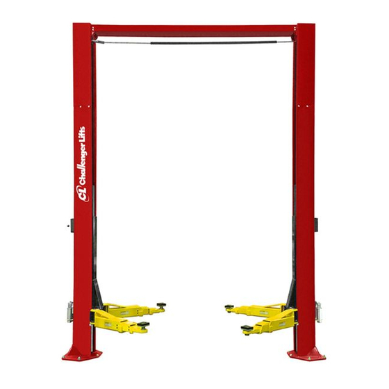
Installation, Operation & Maintenance Manual
Two Post Surface Mounted Lift
200 Cabel Street, P.O. Box 3944 Louisville, Kentucky 40201-3944
Email:
Office 800-648-5438
IMPORTANT:
M
ODEL
12,000
LBS
3000
LBS
sales@challengerlifts.com
/
502-625-0700 Fax 502-587-1933
READ THIS MANUAL COMPLETELY BEFORE
INSTALLING or OPERATING LIFT
CL12
. C
APACITY
.
A
PER
RM
Web site:
www.challengerlifts.com
Rev. 06/16/2014
Advertisement
Table of Contents

Subscribe to Our Youtube Channel
Related Manuals for Challenger Lifts CL12


Summary of Contents for Challenger Lifts CL12
- Page 1 Installation, Operation & Maintenance Manual Two Post Surface Mounted Lift CL12 ODEL 12,000 APACITY 3000 200 Cabel Street, P.O. Box 3944 Louisville, Kentucky 40201-3944 Email: Web site: sales@challengerlifts.com www.challengerlifts.com Office 800-648-5438 502-625-0700 Fax 502-587-1933 IMPORTANT: READ THIS MANUAL COMPLETELY BEFORE INSTALLING or OPERATING LIFT Rev.
-
Page 2: Specifications
Model CL12 Installation, Operation and Maintenance ENERAL PECIFICATIONS See Figure 1 CL12 CL12-1 CL12-2 13’- 8” 14’- 8” 15’- 8” Column Height 13’- 1” 14’- 1” 15’- 1” Floor to Overhead Switch 84 3/4” Rise Height (Screw Pads Highest Position) 5”... -
Page 3: Vertical Clearance
Model CL12 Installation, Operation and Maintenance Safety decals similar to those shown here are found ERTICAL LEARANCE on a properly installed lift. Be sure that all safety Check the height of the area where the lift is to be decals have been correctly installed on the Power installed. -
Page 4: Installation
Fig. 2. 12605 OWER OLUMN SSEMBLY 3) Route cables as shown in figure shown below. 12606 For models CL12-1 and CL12-2, see Fig. 9 on DLER OLUMN SSEMBLY Pg. 7 for cable extension installation. Ensure 12507 VERHEAD cables do not wrap around hoses during routing. - Page 5 Model CL12 Installation, Operation and Maintenance AYOUT 5) Layout the service bay according to the NCHORING architect’s plans or owners instructions (see Fig. 9) The anchor bolts must be installed at least 8” 1b). Failure to install in this orientation can from any crack, edge, or expansion joint.
- Page 6 Model CL12 Installation, Operation and Maintenance 19) Repeat procedure 18 for shut-off bar. Insert VERHEAD shut-off bar in switch tube on power column side 16) Before raising overhead into position install 4 and take other end to idler side. Attach shut-off...
- Page 7 Install (2) hose clamps in overhead and (1) of each carriage for Model CL12-2. Install one hose clamp in each column extension, Fig. 11 . jam nut to cable end before threading cable 1 inch minimum into extension.
-
Page 8: Lock Release
Model CL12 Installation, Operation and Maintenance 26) Install (1) hose clamp on the outside of the ELEASE power column with a 3/8”-16 x 3/4” hex flange 29) On the power column, attach lock cable bolt and 3/8”-16 hex flange nut. Install (1) line assembly to mounting tab using (2) hex jam clamp with a 1/4”-20 x 3/4”... -
Page 9: Arm Installation
Model CL12 Installation, Operation and Maintenance NSTALLATION DAPTER NSTALLATION 36) Extend the foot pad to both extents and apply 42) Locate the two pre-drilled holes on the back of “anti-seize” to the retaining ring. each column 19” up from the top of the base plate and tap 5/16-18. - Page 10 Model CL12 Installation, Operation and Maintenance INAL DJUSTMENTS YDRAULICS 46) Lower the lift to the floor and raise the lift approximately one foot. 47) Start with Idler side first. Slowly and carefully loosen the bleed plug on top of the cylinder just enough to allow the entrapped air to escape.
- Page 11 Model CL12 Installation, Operation and Maintenance Wiring Diagram FOR SINGLE PHASE (Normally Open) FIELD CONECTIONS FOR THREE PHASE FACTORY WIRED FOR 208−240V RECONNECTIONS FOR 440−480V Fig 21 – Electrical Wiring Diagram Page 11 Rev. 06/16/14 CL12-IOM-A.doc...
-
Page 12: Operation Procedure
Model CL12 Installation, Operation and Maintenance 90 ALI Safety Tips card; ANSI/ALI ALOIM-2008, PERATION ROCEDURE American National Standard for Automotive Lifts- AFETY OTICES AND ECALS Safety Requirements for Operation, Inspection and Maintenance; and in the case of frame This product is furnished with graphic safety... - Page 13 Model CL12 Installation, Operation and Maintenance IFTING A EHICLE 5) Continue to lower the vehicle until the carriages stop against the base plate. Retract the extension 1) Insure that the lifting arms are parked, out to full arms, and park them.
-
Page 14: Maintenance
• Check for loose or broken parts. • Check hydraulic system for fluid leaks. • Check adapters for damage or excessive wear. Replace as required with genuine Challenger Lifts parts. • Check the lock release activation. When properly adjusted, both locks should be in a vertical position... -
Page 15: Parts Breakdown
Items (2, 24, 52, 62, 63, 64, 66) 12502-188H COLUMN EXTENSION PACK FOR CL12-2 Replace all worn, damaged, or broken parts with parts approved by Challenger Lifts Inc. or with parts meeting Challenger Lifts Inc. specifications. Contact your local Challenger Lifts Parts Distributor for pricing and availability. - Page 16 STACK ADAPTER EXTENSION – 6” B2201 FRAME ENGAGING ADAPTER (not shown) Replace all worn, damaged, or broken parts with parts approved by Challenger Lifts Inc. or with parts meeting Challenger Lifts Inc. specifications. Contact your local Challenger Lifts Parts Distributor for pricing and availability.
- Page 17 31118 ZIP TIE (FOR LIMIT SWITCH CORD) Replace all worn, damaged, or broken parts with parts approved by Challenger Lifts Inc. or with parts meeting Challenger Lifts Inc. specifications. Contact your local Challenger Lifts Parts Distributor for pricing and availability.
- Page 18 CABLE EXTENSION (CL12-1) 12574 CABLE EXTENSION (CL12-2) Replace all worn, damaged, or broken parts with parts approved by Challenger Lifts Inc. or with parts meeting Challenger Lifts Inc. specifications. Contact your local Challenger Lifts Parts Distributor for pricing and availability.
- Page 19 INNER GEAR B1068 M10x25 HEX FLANGE HEAD BOLT Replace all worn, damaged, or broken parts with parts approved by Challenger Lifts Inc. or with parts meeting Challenger Lifts Inc. specifications. Contact your local Challenger Lifts Parts Distributor for pricing and availability.
Need help?
Do you have a question about the CL12 and is the answer not in the manual?
Questions and answers