
Related Manuals for Austin Hughes Electronics Cyberview NCP-1716


Summary of Contents for Austin Hughes Electronics Cyberview NCP-1716
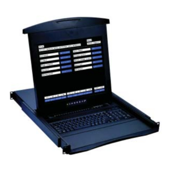
- Page 1 User Manual NCP-1716 16-port Console Terminal LCD Keyboard Drawer - 1U 17" screen size - Designed for SUN, all headless servers...
-
Page 3: Table Of Contents
Chapter 1 Getting Started Important Safeguards...1 Regulatory Notice...2 Package Contents...3 Before Installation...4 Unpacking...4 Optional Accessories...4 Structure Diagram...5 Installation...6 How to Use "N" Series LCD Keyboard Drawer...7 1.10 How to Use the Slides ...8 1.11 How to Use "One Man" Installation Slides ...9-10 Chapter 2 How to Connect Keyboard Drawer Connection Diagram...11... - Page 4 Chapter 5 System Status & Log Chapter 6 System Setting System Administration...43-44 Date and Time...45 Fireware Upgrade...46-47 Chapter 7 Operation On-screen Display Operation...48 On-screen Menu...49 Chapter 8 Standard Specifi cation Specifi cations...50 Keyboard...51 Chapter 9 Optional Specifi cation DC Power Options...51 Chapter 10 FAQ ...52-53 Chapter 11 Dimensions...
-
Page 5: Important Safeguards
1.1 Important Safeguards Please read all of these instructions carefully before you use the device. Save this manual for future reference. What the warranty does not cover ■ Any product, on which the serial number has been defaced, modifi ed or removed. ■... -
Page 6: Regulatory Notice
1.2 Regulatory Notice Legal Information First English printing, October 2002 Information in this document has been carefully checked for accuracy; however, no guarantee is given to the correctness of the contents. The information in this document is subject to change without notice. We are not liable for any injury or loss that results from the use of this equipment. -
Page 7: Package Contents
RJ45-DB9 male adapter x 1 pc Fasteners for rear L-bracket x 4 pcs 330mm rear mounting L-bracket x 1 pair * NCP-1716 mounting depth-adjustable from 320 to 920mm User manual x 1 pc CD disc x 1 pc Power cord x 1 pc... -
Page 8: Before Installation
1.4 Before Installation ■ It is very important to locate the console terminal LCD keyboard drawer in a suitable environment. ■ The surface for placing and fi xing the Console Terminal Drawer should be stable and level or mounted into a suitable cabinet. -
Page 9: Structure Diagram
1.7 Structure Diagram Carry handle to release the 2-pt lock 2-point lock LCD interchangeable module kit LCD membrane Adjustable rear mounting L-bracket Micro switch for screen auto power off Serial port status LED Keyboard interchangeable module kit Chapter 1... -
Page 10: Installation
1.8 Installation Figure 1. Installing the rear L-bracket to the LCD keyboard drawer. Figure 2. Aligning the rear L-brackets to a suitable length for the rack. Figure 3. Fixing the LCD keyboard drawer into the rack. ■ Install each rear L-bracket using two fasteners shown in Figure 1. -
Page 11: How To Use "N" Series Lcd Keyboard Drawer
1.9 How to Use "N" Series LCD Keyboard Drawer Figure 4. Pulling the tab toward the front of LCD. Figure 5. Flipping up the LCD to a suitable angle. ■ Gently pull the tab toward the front of the LCD shown in Figure 4. -
Page 12: How To Use The Slides
1.10 How to Use the Slides Figure 7. White arrow button. Figure 8. Pushing the white arrow button. Figure 9. Pushing the LCD keyboard drawer into the rack. ■ A white arrow release button is located on the outside of each slide (shown in Figure 7). ■... -
Page 13: Install The Front Mounting Ear X 2 Pcs
1.11 How to Install "One Man" Installation Slides Package Contents Install the front mounting ear x 2 pcs ■ Disassemble the standard front mounting ears carefully. ■ Install the optional front mounting ears with M3.2*4.5mm screw x 8 pcs. Chapter 1 Model No : NBK-01 Mounting bracket x 2 pcs Front mounting ear (left &... -
Page 14: Install Into Rack
1.11 How to Install "One Man" Installation Slides Install into Rack ■ Attach mounting brackets to vertical mounting rails. ■ Leaving the screws slightly loose. ■ Attach support brackets to chassis with M3.2*4.5mm screw x 6 pcs ■ Pickup the unit. ■... -
Page 15: Connection Diagram
2.1 Connection Diagram NCP-1716 Ethernet Console Cat5 cable Internet Hub remote access Cat5 cable SG-100M RJ45-DB9 male adapter Router Switch Power module Serially Headless servers managed device P.11 Chapter 2 Cat5 cable SG-100F RJ45-DB9 female adapter... -
Page 16: Membrane
2.2 Membrane Power ON ■ Turn off all devices / servers and Cat5 IP serial console ■ Make sure all cables / connectors are properly connected Front Panel - Port LED Indications 16 ports Power Link Ready Port LED Reset button Warning : Press “Shift+Esc”... -
Page 17: Confi Guring The Local Console
2.3 Confi guring the Local Console Switch on the power on the rear of NCP-1716. (It takes about 60 seconds to initialize the device. Please do not input any key while initalize the device Entering SETUP Hold down the key and then depress the When you enter SETUP mode, any text on the screen temporarily disappears, and the main SETUP directory appears. - Page 18 2.3 Confi guring the Local Console The 16-port serial console drawer with serial-to-serial local access function which the data transfer can be between one designated serial port (ESP) and one of the other serial ports. Select the access port and confi gure each setting & type in the value for Inactivity timeout Press SPACE bar to select other itemts 11-59 ===============================================================...
- Page 19 2.3 Confi guring the Local Console Type in user name and password. The default login name & password are “root” User Default Name Password root root Press Ctrl keys to get out of Serial-to-Serial function and back to main console screen. P.15 Chapter 2...
-
Page 20: Changing Operating Parameters
2.4 Changing Operating Parameters To select one of the setup menu’s shown, press the indicated function key. The screen for that menu appears with the name highlighted. The fi elds in the middle of the screen, indicate the parameters that you can change in that menu. -
Page 21: General Setup Menu
2.4 Changing Operating Parameters ------------------------------------------------------------------------------------------------------------------------------------------------------------------------------------------------------------------ General SETUP Menu ------------------------------------------------------------------------------------------------------------------------------------------------------------------------------------------------------------------ Personality Preset with VT-100, changing the parameter will cause the local acess console malfunction Sets the display scroll rate to Jump (the rate data is received), Smooth-8 (eight lines Scroll Speed per second), Smooth-4, Smooth-2, or Smooth-1. -
Page 22: F4 Comm Setup Menu
2.4 Changing Operating Parameters ------------------------------------------------------------------------------------------------------------------------------------------------------------------------------------------------------------------ Comm SETUP Menu ------------------------------------------------------------------------------------------------------------------------------------------------------------------------------------------------------------------ Baud Rate Preset with “9600”, changing the parameter will cause the local acess console malfunction Rcv Hndahake Preset with “None”, changing the parameter will cause the local acess console malfunction Data / Stop Bits Preset with “8/1”, changing the parameter will cause the local acess console malfunction Xmt Hndshake Preset with “None”, changing the parameter will cause the local acess console... - Page 23 2.4 Changing Operating Parameters ------------------------------------------------------------------------------------------------------------------------------------------------------------------------------------------------------------------ Tabs Setup Menu ------------------------------------------------------------------------------------------------------------------------------------------------------------------------------------------------------------------ On the tabs setup menu screen, the terminal’s current tab stops are indicated by uppercase T’s displayed along a line of periods that mark each column position. (1) A tab stop in columns 2 through 78 is shown as a T in the upper line of periods (2) A tab stop in columns 79 through 132 is shown as a T in the lower line of periods You can easily determine where tabs are set by moving the cursor across the line and reading the column number displayed on the right side of the screen.
-
Page 24: Lan Setup Menu
2.4 Changing Operating Parameters ------------------------------------------------------------------------------------------------------------------------------------------------------------------------------------------------------------------ Ansbk SET-UP Menu ------------------------------------------------------------------------------------------------------------------------------------------------------------------------------------------------------------------ You can program a message of up to 20 characters to identify the terminal to the computer. Enter the mes- sage at the cursor position. Correct errors by pressing message. CONCEAL hides the answerback message, so it is not displayed in SETUP mode. To save the message in nonvolatile memory, exit SETUP mode with the YES option. -
Page 25: Changing Operating Parameters
2.4 Changing Operating Parameters ------------------------------------------------------------------------------------------------------------------------------------------------------------------------------------------------------------------ Color Set-up Menu ------------------------------------------------------------------------------------------------------------------------------------------------------------------------------------------------------------------ The color functionality differs with emulation. In general VT100, VT220 and ANSI Console work with applications which control the color directly. The remaining personalities associate colors based on existing monochrome video attributes. This section will defi... - Page 26 2.4 Changing Operating Parameters Color Palettes Palette Display Attribute Normal Reverse (or blank)*1 Intensity*2 Intensity*2 and reverse (or blank)*1 Underline Underline and reverse (or blank)*1 Underline and intensity*2,*3 Underline, intensity,*2 and reverse (or blank)*1 Normal Reverse (or blank)*1 Intensity*2 Intensity*2 and reverse (or blank)*1 Underline Underline and reverse (or blank)*1 Underline and intensity*2,*3...
-
Page 27: Changing Operating Parameters
2.4 Changing Operating Parameters Color Palettes Palette Display Attribute Normal Reverse (or blank)*1 Intensity*2 Intensity*2 and reverse (or blank)*1 Underline Underline and reverse (or blank)*1 Underline and intensity*2,*3 Underline, intensity,*2 and reverse (or blank)*1 Normal Reverse (or blank)*1 Intensity*2 Intensity*2 and reverse (or blank)*1 Underline Underline and reverse (or blank)*1 Underline and intensity*2,*3... -
Page 28: Local Keyboard Commands In Native Mode
2.5 Local Keyboard Commands in Native Mode ------------------------------------------------------------------------------------------------------------------ Commands ------------------------------------------------------------------------------------------------------------------ Toggle CAPS LOCK on/off Toggle NUM LOCK on/off Put terminal in SETUP mode Partially reset terminal, including communication unlock keyboard, turn off all print modes. Send break* Toggle between block and full-duplex modes Print Screen formatted Turn auxiliary print mode on/off Turn monitor mode on/off... -
Page 29: Connector Pin Assignment
2.6 Connector Pin Assignment Pin 1 Pin 8 Console port & serial port pin assignment Signal Direction P.25 Chapter 2... -
Page 30: Command Guide
2.7 Command Guide Commands Supported in ASCII Personalities Below table lists all the ASCII commands recognized by the terminal. The native mode code for the com- mand is given in the second column. (The native mode include WY-325,WY-120 and WY-60.) The remaining columns show the support for the command in other ASCII personalities according to the following notations: Same as native code (code is native to other terminal also) Same -... -
Page 31: Device Setup
2.8 Device Setup 2.1.2 Setup the IP address from Ethernet port In addition to VT100 interface, we also provide a Network Setup Software tool (IPCS Setup) for the network settings to the IP serial console. The operation procedures are as follows: 1. -
Page 32: Device Setup
Chapter 2 2.8 Device Setup 2.1.3 Web Management Interface The IP serial console (IPCS) supports both HTTP and HTTPS (HTTP over SSL) protocols. The user must authenticate themselves by logging into the system with a correct user name and password To access the IP serial console Web management pages, enter the pre-set IP address or resolvable hostname into the web browser’s URL/Location field. -
Page 33: Ip Confi Guration
3.1 IP Confi guration User can do the network IP settings via V-100 or web pages. This chapter describes the usage of web pages. The default IP settings are as follows. 3.1.1 IP Configuration The IP serial console requires a valid IP address to operate within the user’s network environment. If the IP address is not readily available, contact the system administrator to obtain a valid IP address for the IP serial console. -
Page 34: Ip Filtering
3.2 IP Filtering 3.2.1 IP Filtering The IP filtering function keeps unauthorized hosts from accessing to the IP serial console by specifying IP filtering rules. It is important to fully understand what an IP filter is. If you don’t fully understand this, you will get unexpected results against your original plan. -
Page 35: Web Server Confi Guration
3.2 IP Filtering 3.2.1 IP Filtering Users can add a new IP filtering rule by setting the properties at adding line and then clicking the button Add. User can remove a rule by clicking the button Remove. In the example above, no host is allowed to connect to the IPCS through http (port 80) by the #3 rule but the hosts whose subnet is 192.168.1.x is allowed by the #1 rule and 192.168.2.x by the rule #2. - Page 36 3.3 Web Server Confi guration 3.3.2 Dynamic DNS When users connect the IP serial console (IPCS) to a DSL line or use a DHCP configuration, and get a dynamic IP address from the network, the IP address may not the same as previous. It can therefore be very difficult to know if an IP address has changed, or what the new IP address is.
-
Page 37: Web Server Confi Guration
Chapter 3 3.3 Web Server Confi guration 3.3.4 RADIUS Authentication is the process of identifying an individual, usually based on a username and password. The IP serial console supports various authentication options, such as Local, RADIUS, to authenticate the users who access the serial port. -
Page 38: Chapter 4 Serial Port Confi Guration
4.1 Serial Port Confi guration Under the Serial Port heading, click Configuration will show the list of port summary as below. 4.1.1 Port Authentication Authentication is the process of identifying an individual, usually based on a username and password. The IP serial console supports various authentication options, such as Local, RADIUS, to authenticate the users who access the serial port. - Page 39 Chapter 4 4.1 Serial Port Confi guration 4.1.3 Port Title Users can enter descriptive information for each port based on the device attached to it. We can use the shortcut Move to on the up-right corner to go to the wished port page directly P.35...
- Page 40 4.1 Serial Port Confi guration 4.1.4 Operation Modes The IP serial console unit provides four types of operation modes. These are described in the following sections. Note : ■ The Power Control Mode is available in port #1 only. ■ The last port (e.g., Port #16 of IPCS-16) can also be used as External ESP (Entry Serial Port) in Serial-to-Serial operation mode.
- Page 41 Chapter 4 4.1 Serial Port Confi guration Console Server Mode Configuring a serial port as a console server creates a TCP socket on the IP serial console unit that listens for a Telnet or SSH client connection. When you connect to the TCP socket, you have access to the device attached to the serial port as if the device were connected directly to the network.
- Page 42 4.1 Serial Port Confi guration 4.1.5 Serial Port Parameters To connect the serial device to the IPCS serial port, the serial port parameters of the IPCS should match exactly to that of the serial device attached. 4.1.6 Port Logging With the Port logging feature while in console server mode, the data receiving from the tracking serial port will be buffered in IPCS memory.
-
Page 43: Serial Port Confi Guration
4.1 Serial Port Confi guration 4.1.6 Port Logging If Port logging option is enabled, the user can let the IP serial console to search a defined keyword from the port logging data and send an email to an administrator by Port event handling configurations. Each reaction can be configured individually upon each keyword. -
Page 44: Connection
Chapter 4 4.2 Connection 4.2.1 Telnet Java Applet 1. Select Telnet protocol under Serial port > Configuration > Operation mode. 2. Select the Serial port > connection menu item, click the terminal icon at C column. If connect success, the terminal emulation will pop up login prompt. 3. -
Page 45: Serial-To-Serial Function
4.3 Serial-to-Serial Function 4.3.1 Serial-to-Serial Function The web page also gives read-only settings of Serial-to-Serial function, it will auto-changed upon the setting change on VT100 console. Click Cancel will refresh the values. 4.3.2 Serial Power Control Function The Serial Power Controller (SPC) is a family of intelligent power distribution units that enables remote power control of servers and network appliances. -
Page 46: System Status & Log
5.1 System Status & Log 5.1.1 System Status System status data include the model name, serial number, firmware version, bootloader version, current time, and the network configuration of the IP serial console. User cannot change the data from this page. This page will be automatically refreshed every 10 seconds, to show the system current time. -
Page 47: System Administration
6.1 System Administration 6.1.1 User Administration At startup of the AP, the system will prompt user to enter the password to access to the system. The administrator can add or remove a user easily via the web pages. There are two levels of access privileges: User Name root (user define) - Page 48 6.1 System Administration 6.1.3 Remove User To remove a user, ■ Check the users at the User administration screen ■ Click the button Remove 6.1.4 Edit ACL IPCS Provides ACL (Access Control List) security function, each user may be authorized to access to certain ports only, instead of all ports.
-
Page 49: Date And Time
6.2 Date and Time The IPCS maintains current date and time information. The IPCS clock and calendar settings are backed up by internal battery power. The user can change the current date and time. There are two methods of date and time settings. The first is to use the NTP server to maintain the date and time settings. If the NTP feature is enabled, the IPCS will obtain the date and time information from the NTP server at each reboot, then automatically align with the NTP server time per hour. -
Page 50: Fireware Upgrade
6.3 Fireware Upgrade Firmware can be easily upgraded via web page. This section describes the upgrade procedures. *Pls contact you The latest firmware version is available on the web site. 6.3.1 Prepare Upgrade Environment Need to obtain a TFTP server software program. Startup tftp server (e.g., tftpd32). -
Page 51: Fireware Upgrade
6.3 Fireware Upgrade 6.3.2 Upgrade from web page If you want to run the new firmware, you need to click the Reboot item, then Yes to confirm to reboot the system. It will take about one minute to finish the system reboot. When the IPCS unit finishes the startup and working normally, the Ready green LED will blink every second. -
Page 52: On-Screen Display Operation
7.1 On-screen Display Operation Membrane Switch Function Power light Green = On Orange = Power saving Power on / off LCD Display the OSD menu Scrolls through menu options and adjusts the displayed control Exit the OSD screen Shortcut key to auto adjustment by pressing the button for 5 seconds 17"... -
Page 53: On-Screen Menu
7.2 On-screen Menu MAIN MENU BRIGHTNESS/CONTRAST AUTO ADJUST PHASE/CLOCK H/V POSITION MISC RESET BRIGHTNESS / CONTRAST Brighthtness: Adjust background black level of the screen image. Contrast: Adjust the difference between the image background (black level) and the foreground (white level). AUTO ADJUST Auto Adjust: Fine tunes the video signal to eliminate waviness and distortion. -
Page 54: Specifi Cations
8.1 Specifi cations Item Form Factor LCD Manufacturer Diagonal Size Max. Resolution Brightness (cd/m²) Contrast Ratio (typ.) Viewing Angle (H/V) Display Area (mm) Color Support Number of port Connector Signal Serial Interface Flow Baudrate Mode Port LAN Interface Type Mode Security Authentication Protocols... -
Page 55: Keyboard
8.2 Keyboard N keyboard with full numerical pad ■ 104 keys (US / European / Chinese / Korean layout) ■ 106 keys (Japan layout) ■ PS/2 or USB connection 9.1 DC Power Options Model Input rating Input voltage: Input range: Input current - No load - Full load... -
Page 56: Chapter 10 Faq
(4) Then press F12 to exit, and press Spacebar save the setting. Remark : Scroll lock must be off for accessing setup menu by “Alt + Esc” key 4. What devices and servers can the NCP-1716 16-port console terminal LCD keyboard drawer be used with ? - Page 57 10.1 FAQ 9. How long is the cable which can support on each serial port ? The longest cable for supporting serial port is 15 meter. 10. What security features does the 16-port console terminal drawer support? The 16-port console terminal’s user database supports up to 200 user accounts, which include user names, passwords, plus specifi...
-
Page 58: Chapter 11 Dimensions
(W x D x H) (W x D x H) Weight Weight 442 x 650 x 44 mm 589 x 856 x 168 mm 16 kg 22 kg NCP-1716 17.4 x 25.6 x 1.73" 23.2 x 33.7 x 6.6" 35 lb 48 lb P.54... - Page 60 The company reserves the right to modify product specifi cations without prior notice and assumes no reponsibility for any error which may appear in this publication. All brand names, logo and registered trademarks are properties of their respective owners. Copyright 2007 Austin Hughes Electronics Ltd. All rights reserved. CV-NCP22-0807V1...
Need help?
Do you have a question about the Cyberview NCP-1716 and is the answer not in the manual?
Questions and answers