
Related Manuals for Austin Hughes Electronics N117 Series


Summary of Contents for Austin Hughes Electronics N117 Series
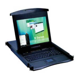
- Page 1 User Manual N Series 1U LCD Keyboard Drawer 17", 19" screen size Models N117 / 119 Series - With KVM options Models N1417 / 1419 Series - Short depth version - Without KVM options...
-
Page 2: Table Of Contents
Chapter 1 Getting Started Important Safeguards...1 Regulatory Notice...2 Package Contents...3 Before Installation...4 Unpacking...4 Optional Accessories...4 Peripheral Products...5 Structure Diagram...5 Installation...6 1.10 How to Use "N" Series LCD Keyboard Drawer...7 1.11 How to Use the Slides...8 1.12 How to Use "One Man" Installation slides ...9 1.13 Connect to Server via USB Interface...11 1.14... -
Page 3: Important Safeguards
1.1 Important Safeguards Please read all of these instructions carefully before you use the device. Save this manual for future reference. What the warranty does not cover ■ Any product, on which the serial number has been defaced, modifi ed or removed. ■... -
Page 4: Regulatory Notice
1.2 Regulatory Notice Legal Information First English printing, October 2002 Information in this document has been carefully checked for accuracy; however, no guarantee is given to the correctness of the contents. The information in this document is subject to change without notice. We are not liable for any injury or loss that results from the use of this equipment. -
Page 5: Package Contents
Fasteners for rear L-bracket x 4 pcs 330mm rear mounting L-bracket x 1 pair * N117 / 119 series mounting depth-adjustable from 320 to 920mm * N1417 / 1419 series mounting depth-adjustable from 150 to 750mm CB-6 2-in-1 USB KVM cable x 1 pc... -
Page 6: Before Installation
1.4 Before Installation ■ It is very important to locate the LCD Keyboard Drawer in a suitable environment. ■ The surface for placing and fi xing the LCD Keyboard Drawer should be stable and level or mounted into a suitable cabinet. -
Page 7: Peripheral Products
1.7 Peripheral Products Item Model No. IP-802 / IP-1602 CV-802 / CV-1602 DB-15 KVM CV-401 / CV-801 / CV-1601 CV-S801 / CV-S1601 UIP-1602 / UIP-3202 U-1602 / U-3202 Cat5 KVM U1601 / U3201 IP-101 CV-101 KVM Extender CV-S101 1.8 Structure Diagram Carry handle to release the 2-pt lock 2-point lock LCD interchangeable module kit... -
Page 8: Installation
1.9 Installation Figure 1. Installing the rear L-bracket to the LCD keyboard drawer. Figure 2. Aligning the rear L-brackets to a suitable length for the rack. Figure 3. Fixing the LCD keyboard drawer into the rack. ■ Install each rear L-bracket using two fasteners shown in Figure 1. -
Page 9: How To Use "N" Series Lcd Keyboard Drawer
1.10 How to Use "N" Series LCD Keyboard Drawer Figure 4. Pulling the tab toward the front of LCD. Figure 5. Flipping up the LCD to a suitable angle. Figure 6. Operating the LCD keyboard drawer ■ Gently pull the tab toward the front of the LCD shown in Figure 4. -
Page 10: How To Use The Slides
1.11 How to Use the Slides Figure 7. White arrow button. Figure 8. Pushing the white arrow button. Figure 9. Pushing the LCD keyboard drawer into the rack. ■ A white arrow release button is located on the outside of each slide (shown in Figure 7). ■... -
Page 11: Install The Front Mounting Ear X 2 Pcs
1.12 How to Install "One Man" Installation Slides Package Contents Install the Front Mounting Ear x 2 pcs ■ Disassemble the standard front mounting ears carefully. ■ Install the optional front mounting ears with M3.2*4.5mm screw x 8 pcs. Chapter 1 Model No : NBK-01 Mounting bracket x 2 pcs Front mounting ear (left &... - Page 12 1.12 How to Install "One Man" Installation Slides Install into Rack ■ Attach mounting brackets to vertical mounting rails. ■ Leaving the screws slightly loose. ■ Attach support brackets to chassis with M3.2*4.5mm screw x 6 pcs ■ Pickup the unit. ■...
-
Page 13: Connect To Server Via Usb Interface
1.13 Connect to Server via USB Interface Figure 10. Example of connecting CB-6 2-in-1 USB KVM cable to server via USB interface 1.14 Connect to KVM via USB Interface Figure 11. Example of connecting CB-6 2-in-1 USB KVM cable to KVM via USB interface Remarks : ■... -
Page 14: Connect To Server Via Ps/2 Interface
1.15 Connect to Server via PS/2 Interface Figure 12. Example of connecting CD-6 3-in-1 PS/2 KVM cable to server via PS/2 interface 1.16 Connect to KVM via PS/2 Interface Figure 13. Example of connecting CD-6 3-in-1 PS/2 KVM cable to KVM via PS/2 interface Remarks : ■... -
Page 15: On-Screen Display Operation
2.1 On-screen Display Operation Membrane Switch Function Power light Green = On Orange = Power saving Power on / off LCD Display the OSD menu Scrolls through menu options and adjusts the displayed control Exit the OSD screen Shortcut key to auto adjustment by pressing the button for 5 seconds Toggle analog, digital &... -
Page 16: On-Screen Menu
2.2 On-screen Menu MAIN MENU BRIGHTNESS/CONTRAST AUTO ADJUST PHASE/CLOCK H/V POSITION MISC RESET BRIGHTNESS / CONTRAST Brighthtness: Adjust background black level of the screen image. Contrast: Adjust the difference between the image background (black level) and the foreground (white level). AUTO ADJUST Auto Adjust: Fine tunes the video signal to eliminate waviness and distortion. -
Page 17: Specifi Cations
3.1 Specifi cations Item Form Factor LCD Manufacturer Diagonal Size Max. Resolution Brightness (cd/m²) Color Support Contrast Ratio (typ.) Viewing Angle (H/V) Display Area (mm) Tr Response Time (ms) VGA Signal Input Sync. Type Resolution Plug & Play DDC Console Port (Combo) Power Input Power Consumption Compatilibity... -
Page 18: Keyboard & Mouse
3.2 Keyboard & Mouse N keyboard integrated with touchpad N keyboard integrated with trackball P.16 Chapter 3 Supporting layouts... -
Page 19: Kvm Options
4.1 KVM Options Our KVM is designed to seamlessly integrate into the rear of our full range of LCD drawer solutions: ■ For KVM operation, please refer to "Integrated LCD KVM Switch" user manual ■ Option with high desnsity Cat5 KVM with either 16 or 32 ports ■... -
Page 20: S-Video + Bnc Input Option
Chapter 4 4.4 S-Video + BNC Input Option 3-in-1 VGA KB mouse Internal power version S-Video BNC console port External power version Remarks : ■ Package includes an extra 6ft S-Video cable P.18... -
Page 21: On-Screen Menu For Dvi, Bnc, S-Video & Rca Input
4.5 On-screen Menu for DVI, BNC, S-Video & RCA Input Image Brightness: Adjust background black level of the screen image Contrast: Adjust the difference between the image background (black level) and the foreground (white level) Sharpness: Adjust the image from weak to sharp Saturation: Adjust the saturation of the image color Hue:... -
Page 22: Dc Power Options
4.6 DC Power Options Model Input rating Input voltage: Input range: Input current - No load - Full load Output rating Output voltage: Output current: Effi ciency Remarks : ■ Package does not include power cord and AC power adapter 12-Volt 24-Volt 9 ~ 18V... -
Page 23: Chapter 5 Troubleshooting
Chapter 5 5.1 Troubleshooting 1. How do I adjust the resolution? To change monitor resolution, click Start -> Control Panel -> Display. Select Setting tab to adjust the monitor resolution in Desktop Area. The available resolutions, "640 x 480", "800 x 600", "1024 x 768", "1152 x 864", "1280 x 1024", are deter- mined by the display card in your computer. -
Page 24: Chapter 6 Dimensions
The company reserves the right to modify product specifi cations without prior notice and assumes no reponsibility for any error which may appear in this publication. All brand names, logo and registered trademarks are properties of their respective owners. Copyright 2007 Austin Hughes Electronics Ltd. All rights reserved. Packing Dimension (W x D x H)
Need help?
Do you have a question about the N117 Series and is the answer not in the manual?
Questions and answers