Table of Contents
Advertisement
Available languages
Available languages
Quick Links
Advertisement
Chapters
Table of Contents

Related Manuals for baltur GI MIST 1000 DSPGM


Summary of Contents for baltur GI MIST 1000 DSPGM
- Page 1 Instruction manual Manuale istruzioni per l'uso GI MIST 1000 DSPGM - BRUCIATORI MISTI GAS / GASOLIO A DUE STADI PROGRESSIVI / MODULANTI - PROGRESSIVE/MODULATING TWO-STAGE MIXED GAS/DIESEL BURNERS ISTRUZIONI ORIGINALI (IT) ORIGINAL INSTRUCTIONS (IT) 0006080764_201312...
-
Page 3: Table Of Contents
SCOPO DEL MANULE Il manuale si propone di contribuire all’utilizzo in sicurezza dei componenti per impianti di riscaldamento ad uso civile e produzione di acqua calda per uso sanitario, mediante l’indicazione di quei comportamenti necessari da adottare al fine di evitare alterazioni delle caratteristiche di sicurezza derivanti da eventuali installazioni non corrette, usi erronei, impropri o irragionevoli. - Page 4 4 Responsabilità. 4.1 La Baltur S.p.A. non è in alcun modo responsabile per cause non imputabili a difetti di conformità del prodotto e risponde nei limiti di quanto previsto al punto “2 Termini e decorrenza della garanzia convenzionale.” e di quanto stabilito nella Direttiva 1999/44/CE.
- Page 5 DICHIArAZIONE DI CONFOrmITÁ Dichiarazione di Conformità CE0085: DVGW CERT GmbH, Josef-Wirmer Strasse 1-3 – 53123 Bonn (D) Dichiariamo che i nostri bruciatori ad aria soffiata di combustibili liquidi, gassosi e misti, domestici e industriali, serie: BPM...; BGN…; BT…; BTG…; BTL…; TBML...; Comist…; GI…; GI…Mist; Minicomist…;...
- Page 6 L’eventuale riparazione dei prodotti dovrà essere effettuata solamente vigenti. da un centro di assistenza autorizzato dalla BALTUR utilizzando d) Verifi care la funzionalità dei dispositivi di regolazione e di sicurezza. esclusivamente ricambi originali. Il mancato rispetto di quanto sopra, può...
- Page 7 AVVERTENZE PER L’UTENTE PER L’USO IN SICUREZZA DEL BRUCIATORE ALIMENTAZIONE ELETTRICA - b) la regolazione della portata del combustibile secondo la potenza • La sicurezza elettrica dell’apparecchio è raggiunta soltanto quando lo richiesta al bruciatore; stesso è corretamente collegato a un’efficace impianto di messa a terra, - c) che il bruciatore sia alimentato dal tipo di combustibile per il quale eseguito come previsto dalle vigenti norme di sicurezza.
-
Page 8: Caratteristiche Tecniche
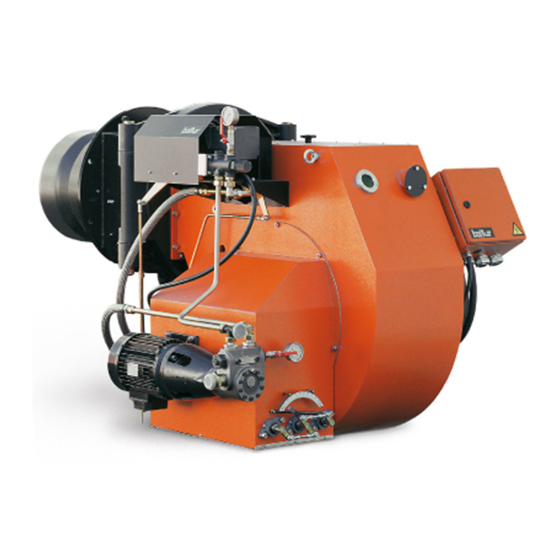
CArATTErISTICHE TECNICHE GI mist 1000 DSPGM 10 500 POTENZA TERMICA 2 500 1 056 PORTATA PRESSIONE INGRESSO AL REGOLATORE mbar 8kV - 20mA TRASFORMATORE 10 500 POTENZA TERMICA 2 500 kg/h PORTATA kg/h 1,5° E - 20° C VISCOSITA’ MAX COMBUSTIBILE... - Page 9 DIMENSIONI DI INGOMBRO Mod. E Ø GI mist 1000 DSPGM 1465 1260 2350 Mod. F Ø L Ø N Ø GI mist 1000 DSPGM DN80 Rp1/2 1910 1575 7 / 42 0006080764 _201312...
-
Page 10: Descrizione Bruciatori Industriali
CAMPO DI LAVORO Gasolio Potenza termica DESCrIZIONE BrUCIATOrI INDUSTrIALI Il bruciatore “GI 1000” è in versione monoblocco ed è costituito da termico si ottiene mediante un servomotore che regola in ma- gruppi forniti separatamente, il collegamento tra questi componenti niera combinata la quantità di aria comburente e di combustibile deve essere realizzato sul posto di installazione del bruciatore, su comando della sonda in caldaia. -
Page 11: Collegamenti Elettrici
COLLEGAmENTI ELETTrICI E’ consigliabile che tutti i collegamenti siano eseguiti con filo elettrico flessibile. Le linee elettriche devono essere distanziate dalle parti calde. Assicurarsi che la linea elettrica a cui si vuol collegare l’apparecchio sia alimentata con valori di tensione e frequenza adatti al bruciatore. - Page 12 SCHEMA IDRAULICO DI PRINCIPIO IMPIANTO DI ALIMENTAZIONE CON REGOLATORE DI PRESSIONE PER BRUCIATORI FUNZIONANTI A COMBUSTIBILE LIQUIDO CON VISCOSITÁ NOMINALE MASSIMA DI 5° E A 50° C 1 - Cisterna principale I serbatoi di recupero olio (diametro ~ 150 mm - altezza ~ 400 mm) devono essere installati il più...
- Page 13 SCHEMA IDRAULICO DI PRINCIPIO ALIMENTAZIONE PER PIÚ BRUCIATORI DI COMBUSTIBILE LIQUIDO CON VISCOSITÁ NOMINALE MASSIMA DI 5° E A 50° C 1 - Cisterna principale I serbatoi di recupero olio (diametro ~ 150 mm - altezza ~ 400 mm) devono essere installati il più vicino possibile al bruciatore ad una 2 - Filtro quota superiore di almeno 0,5 m.
-
Page 14: Descrizione Funzionamento Con Combustibile Liquido
SCHEMA CIRCUITO IDRAULICO REGOLATORE PRESSIONE RITORNO MIN-10 - 12 bar MAX 18-20 FILTRO TUBO FLESSIBILE MANOMETRO 0-40BAR POMPA BRUCIATORE (20-22BAR) 11 RIDUTTORE O STABILIZZATORE DI PRESSIONE (PILOTA) MANOMETRO 0-40BAR 12 PRESSOSTATO GAS MINIMA E MASSIMA CON PRESE DI PRES- SERVOMOTORE DI MODULAZIONE SIONE (PILOTA) DISCO CON VITI DI REGOLAZIONE EROGAZIONE ARIA / 13 VALVOLA GAS DI SICUREZZA FIAMMA D’ACCENSIONE (PILOTA) - Page 15 di un bruciatore rilevi la fiamma dell’altro bruciatore. Questa a vapore), al di sotto del valore di intervento del dispositivo di condizione è ottenuta installando la fotocellula su un supporto arresto, il bruciatore ritorna ad accendersi come precedentemente brandeggiabile, per poter orientare opportunamente la stessa descritto.
- Page 16 PARTICOLARE BRUCIATORE CON GRUPPO POLVERIZZATORE, SERVOMOTORE MODULAZIONE, REGOLATORE PRESSIONE DI RITORNO, REGOLATORE SERRANDA ARIA CON BRUCIATORE PILOTA A GAS G.P.L. O METANO REGOLATORE PRESSIONE RITORNO MIN = 10 + 12 bur MAX = 18 + 20 bur PER VERSIONE ...D TERMOSTAT0 T R U COLLEGAMENTO AL CIRCUITO DI...
- Page 17 PARTICOLARE VALVOLA DI REGOLAZIONE PRESSIONE DEL COMBUSTIBILE Corpo valvola Tappo accesso vite di regolazione Manometro 0 - 40 bar Al ritorno della pompa Dal ritorno gruppo polverizzatore PARTICOLARE VALVOLA REGOLAZIONEPRESSIONE DEL COMBUSTIBILE PER CIRCUITO AUSILIARIO Corpo valvola Molla Tappo di sostegno vite regolazione Otturatore Dado di bloccaggio vite di regolazione Attacco manometro...
- Page 18 UGELLO (CB) CHARLES BERGONZO SMONTATO (SENZA SPILLO) Dati di identificazione ugello: Erogazione in Kg/h Angolo di spruzzo (30°-45°-60°-80°) Anello di tenuta in Viton Rapporto di erogazione (1/3 = B3 – 1/5 = B5) (resistente ail’olio e alta temperatura) Camera di turbolenza Ritorno combustibile Ingresso combustibile Foro uscita combustibile...
-
Page 19: Accensione E Regolazione Combustibile Liquido
ACCENSIONE E rEGOLAZIONE • Aprire ora tutte le saracinesche ed eventuali altri organi di COmBUSTIBILE LIQUIDO intercettazione posti sulle tubazioni del gasolio. • Portare l’interruttore, posto sul quadro di comando, nella posizione • Verificare che le caratteristiche dell’ugello (erogazione ed angolo “O”... - Page 20 ( + e - ). Il valore della corrente di cellula per assicurare il fiamma rossa con presenza di fumo, come pure fiamma bianca funzionamento dell’apparecchiatura è riportato sullo schema con esagerato eccesso di aria. elettrico. • Verificare ora il corretto funzionamento automatico della •...
-
Page 21: Descrizione Funzionamentoa Metano
SCHEMA DI PRINCIPIO REGOLAZIONE “minimo” del regolatore di portata, esce dalla testa di combustione. Il bruciatore è così acceso alla portata minima. PILOTA GAS PER MODELLO Il circuito pilota si disinserisce dopo l’apertura delle valvole principali. Il servomotore di modulazione viene inserito dopo l’apertura delle valvole principali e, se il termostato o pressostato modulante lo consente (regolato ad un valore di temperatura o pressione superiore a quella esistente in caldaia) inizia a girare determinando un aumento... - Page 22 SCHEMA PRINCIPIO RAMPA GAS LIMITE DI FORNITURA BALTUR LIMITE DI FORNITURA BALTUR SERVOMOTORE DI MODULAZIONE DISCO CON VITI DI REGOLAZIONE PER APERTURA E CHIU- SURA ARIA ALLA TESTA DISCO CON VITI DI REGOLAZIONE EROGAZIONE ARIA/GAS VALVOLA GAS DI SICUREZZA FIAMMA D’ACCENSIONE (PI-...
-
Page 23: Accensione E Regolazionea Gas Metano
ACCENSIONE E rEGOLAZIONE • Inserire ora, l’interruttore del quadro di comando e portare gli interruttori della modulazione in posizione MIN (minimo) e MAN A GAS mETANO (manuale). L’apparecchiatura di comando riceve così tensione ed il programmatore determina l’inserzione del bruciatore come •... -
Page 24: Uso Del Bruciatore
USO DEL BrUCIATOrE carbonica (CO ) che aumenta all’aumentare dell’erogazione, indicativamente, per il metano, almeno 8% all’erogazione minima del bruciatore, fino al valore ottimo del 10% per Il bruciatore è a funzionamento completamente automatico; l’erogazione massima. Sconsigliamo di superare il valore del chiudendo l’interruttore generale e quello del quadro di comando 10% per evitare di funzionare con un eccesso di aria troppo il bruciatore viene inserito. - Page 25 viti del disco di modulazione. A regolazione effettuata ricordarsi di bloccare le viti di fissaggio delle viti registrabili. SCHEMA DI PRINCIPIO REGOLAZIONE ARIA REGOLAZIONE NON CORRETTA Grande apertura passaggio aria Testa di combustione Ingresso aria di combustione serrande molto chiuse REGOLAZIONE CORRETTA Passaggio aria relativamente chiuso Attenzione:...
- Page 26 DESCRIZIONE FUNZIONAMENTO SCHEMA DI PRINCIPIO PRESSOSTATO ARIA DIFFERENZIALE REGOLAZIONE PILOTA GAS Il pressostato aria ha lo scopo di mettere in sicurezza (blocco) l’apparecchiatura se la pressione dell’aria non è quella prevista. Il pressostato deve quindi essere regolato per intervenire chiudendo il contatto NO (normalmente aperto) quando la pressione dell’aria nel bruciatore raggiunge il valore sufficiente.
-
Page 27: Istruzioni Valvole Gas
ISTrUZIONI VALVOLE GAS VALVOLE GAS TIPO: VE 4000B1 (...B... = APERTURA - CHIUSURA, RAPIDA, fig.1 REGOLATORE DI PORTATA) CARATTERISTICHE • Valvola normalmente chiusa • Apertura e chiusura rapida • Con regolatore di portata Le valvole VE 4000B1 sono valvole a solenoide in classe A, normalmente chiuse. - Page 28 VALVOLA GAS SKP 15.000 E2 SKP 15... completa con valvola FUNZIONAMENTO Valvole ad uno stadio In caso di segnale di apertura della valvola, la pompa si inserisce e la valvola magnetica si chiude. La pompa trasferisce il volume di olio situato sotto il pistone nella parte superiore dello stesso, il pistone si muove verso il basso e comprime la molla di richiamo di chiusura attraverso lo stelo ed il piattello, la valvola resta in posizione di apertura, la pompa e la valvola magnetica restano sotto tensione.
- Page 29 VALVOLA SKP 25.003 E2 CON SKP 15.../ 25... con connettore AGA62.000A000 REGOLATORE DI PRESSIONE ESECUZIONE Servomotore Il sistema di comando oleoidraulico è costituito da un cilindro pieno di olio e da una pompa con pistone oscillante. É prevista inoltre una elettrovalvola tra la camera di aspirazione e quella di spinta della pompa, per la chiusura.
-
Page 30: Particolare Motore Sqm 10 E Sqm 20 Per Regolazione Cammes
PArTICOLArE mOTOrE SQm 10 E SQm APPArECCHIATUrA DI COmANDO 20 PEr rEGOLAZIONE CAmmES E CONTrOLLO LFL 1.333 .. A p p a r e c c h i d i c o m a n d o e c o n t r o l l o p e r b r u c i a t o r i a d a r i a s o f f i a t a d a m e d i e a g r a n d i p o t e n z i a l i t à... - Page 31 Collegamenti elettrici Per il collegamento della valvola di sicurezza vale lo schema del produttore del bruciatore Legenda per l’intero foglio di catalogo Contatto commutatore di fine corsa per la posizione Termostato o pressostato APERTA della serranda aria Valvola del combustibile a regolazione continua Segnalazione a distanza di un arresto di blocco (allarme) Fusibile Relè...
- Page 32 Note sul programmatore sequenza del programmatore segnali in uscita sulla morsettiera Legenda tempi tempi (50 Hz) in secondi 31,5 Tempo di pre-ventilazione con serranda aria aperta Intervallo dall’avvio all’inizio del controllo della pressio- ne aria senza tempo di corsa reale della serranda aria Tempo di sicurezza Tempo di corsa della serranda in apertura t2’...
- Page 33 t2´, t3´, t4´: nel circuito di controllo della fiamma ecc.) Questi intervalli sono validi solo per gli apparecchi di comando Interruzione della sequenza di avviamento, perché il se- e controllo bruciatore serie 01, ovvero LFL1.335, LFL1.635, gnale APERTO non è stato inviato al morsetto 8 dal contatto LFL1.638.
-
Page 34: Apparecchiatura Di Controllo Tenuta Valvole Gas Ldu 11
APPArECCHIATUrA DI CONTrOLLO Questo circuito normalmente è quello del consenso al circuito di comando di avviamento dell’apparecchiatura. TENUTA VALVOLE GAS LDU 11... Dopo la chiusura del circuito tra i morsetti 3 e 6 il programmatore dell’LDU 11 ... ritorna nella posizione di riposo e si arresta, cioè Impiego predispone per una nuova verifica, senza modificare la posizione L’apparecchio LDU 11 .. -
Page 35: Smontaggio Gruppo Polverizzatore E Disco Fiamma
segnalazione di allarme a distanza relè principale con i contatti ‘ar...’ fusibile dell’apparecchio relè di blocco con i contatti ‘br...’ pressostato esterno (controllo della tenuta) pulsante di sblocco pressostato esterno (della pressione del gas di rete) relè ausiliario con i contatti ‘hr...’ lampada di segnalazione anomalia dell’apparecchio interruttore di linea I ... - Page 36 2 - Scollegare tirante gruppo polverizzatore e testa scorrevole 3 - Scollegare connettore resistenze 4 - Scollegare connettore cavo elettrodo accensione 5 - Svitare dado per raccordo Woss per estrarre tubo pilota 6 - Sfilare perno cerniera 7 - Estrarre vite superiore cerniera e aprire bruciatore 8 - Estrarre vite di bloccaggio gruppo polverizzatore 9 - Sfilare il gruppo polverizzatore per smontare l’ugello 10 - Estrarre n°...
-
Page 37: Schema Elettrico
SCHEmA ELETTrICO 35 / 42 0006080764 _201312... - Page 38 36 / 42 0006080764 _201312...
- Page 39 37 / 42 0006080764 _201312...
- Page 40 38 / 42 0006080764 _201312...
- Page 41 39 / 42 0006080764 _201312...
- Page 42 40 / 42 0006080764 _201312...
- Page 43 41 / 42 0006080764 _201312...
- Page 44 COMANDO CAMBIO COMBUSTIBILE A DISTANZA (APERTO=GAS,CHIUSO=COMBUSTIBILE APPARECCHIATURA LIQUIDO) CONTROLLO TENUTA VALVOLE TERMOSTATO 2 STADIO FOTOCELLULA UV TRASFORMATORE D'ACCENSIONE PRESSOSTATO CONTROLLO TENUTA VALVOLE TERMOSTATO CALDAIA RELE’ TERMICO PONTE RADDRIZZATORE RELE’ TERMICO POMPA MORSETTIERA QUADRO ELETTRICO FU1÷4 FUSIBILI X1B/S CONNETTORE ALIMENTAZIONE SPIA DI FUNZIONAMENTO MORSETTIERA BRUCIATORE SPIA FUNZIONAMENTO OLIO X2B/S...
- Page 45 PURPOSE OF THIS MANUAL This manual is aimed at ensuring the safe use of the components of heating systems for domestic use and the production of hot water. They indicate the proper behaviour to prevent the original safety features from being jeopardized by improper or erroneous installation and by improper, erroneous or unreasonable use.
- Page 46 2 / 42 0006080764 _201312...
- Page 47 STATEMENT OF CONFORMIT Statement of Conformity CE0085: DVGW CERT GmbH, Josef-Wirmer Strasse 1-3 – 53123 Bonn (D) We hereby declare under our own responsibility, that our domestic and industrial blown air burners fired by gas, oil and dual fuel series: BPM...;...
- Page 48 In such case get in touch with only qualifi ed technicians. Any c) Carry out a check on combustion to ensure the production of no- product repairs must only be carried out by BALTUR authorised assi- xious or polluting unburnt gases does not exceed limits permitted stance centres using only original spare parts.
- Page 49 WARNING NOTES FOR THE USER HOW TO USE THE BURNER SAFELY Special warning notes when using gas ELECTRICAL SUPPLY • Have qualifi ed technicians check the following: • The equipment is electrically safe only when it is correctly connected to an effi cient ground connection carried out in accordance with current safety a) that the feed line and the train comply with current law and regulations.
-
Page 50: Technical Data
TECHNICAL dATA GI mist 1000 DSPGM 10 500 HEATING CAPACITY 2 500 1 056 FLOW RATE REGULATOR INLET PRESSURE mbar 8kV - 20mA TRANSFORMER 10 500 HEATING CAPACITY 2 500 kg/h FLOW RATE kg/h 1.5° E - 20° C MAX FUEL VISCOSITY... - Page 51 OVERALL DIMENSIONS Mod. E Ø GI mist 1000 DSPGM 1465 1260 2350 Mod. F Ø L Ø N Ø GI mist 1000 DSPGM DN80 Rp1/2 1910 1575 7 / 42 0006080764 _201312...
-
Page 52: Description Of The Industrial Burners
OPERATING RANGE Diesel Thermal power dESCRIPTION OF THE INdUSTRIAL BURNERS The GI 1000 burner is a packaged version made up of separately “GI 1000” series burners are modulating with a modulating supplied units; these components must be connected at the burner range of 1 - 4. -
Page 53: Electrical Connections
ELECTRICAL CONNECTIONS It is advisable to make all connections with flexible electric wire. The electric lines should be at an adequate distance from hot parts. Make sure that the electric line to which the unit will be connected has frequency and voltage ratings suitable for the burner. Check that the main line, the relevant switch with fuses (essential) and the current limiter (if required) are capable of withstanding the maximum current absorbed by the burner. - Page 54 SUPPLY HYDRAULIC DRAWING FOR LIQUID FUEL BURNERS WITH MAXIMUM NOMINAL VISCOSITY (5°E AT 50°C) WITH PRESSURE REGULATOR 1 - Main tank The oil recovery tanks (diameter ~ 150 mm - height ~ 400 mm) must be installed as close as possible to the burner at least 0.5 2 - Filter m above the burner pump.
- Page 55 SUPPLY HYDRAULIC DRAWING FOR SEVERAL LIQUID FUEL BURNERS WITH MAXIMUM NOMINAL VISCOSITY (5°E AT 50°C) 1 - Main tank The oil recovery tanks (diameter ~ 150 mm - height ~ 400 mm) must be installed as close as possible to the burner at least 0.5 m 2 - Filter above the burner pump.
-
Page 56: Functional Description With Liquid Fuel
HYDRAULIC DIAGRAM RETURN PRESSURE REGULATOR MIN 10-12 bar MAX 18-20 bar FILTER 10 PRESSURE GAUGE 0-40 BAR HOSE 11 REDUCTION UNIT OR (PILOT) PRESSURE STABILISER BURNER PUMP (20-22 BAR) 12 GAS MINIMUM AND MAXIMUM PRESSURE SWITCH WITH PRESSURE GAUGE 0-40 BAR (PILOT) PRESSURE INTAKES MODULATION SERVOMOTOR 13 IGNITION FLAME SAFETY GAS VALVE (PILOT) - Page 57 Just 2.5 seconds after the ignition of the pilot flame, the control box powers the magnet which, via a series of lever mechanisms, moves The air pressure switch must be adjusted on igniting the the two nozzle fuel flow (delivery and return) interception rods. burner as a function of the pressure value observed for When the rods move back they close the atomization unit internal operation with the pilot flame.
- Page 58 DETAIL OF BURNER WITH ATOMIZER UNIT, MODULATION SERVOMOTOR, RETURN PRESSURE REGULATOR, AIR GATE REGULATOR WITH LPG OR NATURAL GAS PILOT BURNER RETURN PRESSURE REGULATOR MIN = 10 + 12 bar MAX = 18 + 20 bar FOR VERSION ...D THERMOSTAT T R U CONNECTION TO POWER SUPPLY CIRCUIT SEE 0002901120 FOR ONE...
- Page 59 DETAIL OF FUEL PRESSURE ADJUSTING VALVE Valve body Adjusting screw tap Pressure gauge 0- 40 bar To the pump return pipe From the atomizing group return pipe DETAIL OF FUEL PRESSURE ADJUSTING VALVE FOR AUXILIARY CIRCUIT Valve body Spring Adjusting screw support plug Shutter Adjusting screw stop nut Pressure gauge connection...
- Page 60 DISMANTLED ( C.B. ) CHARLES BERGONZO NOZZLE (WITHOUT PIN) Nozzle rating data: Flow rate kg/h Spray angle (30° - 45° - 60° - 80°) Viton seal ring Output ratio (1/3 = B3 - 1/5 = B5) (oil and temperature resistant) Fuel outlet Fuel return Fuel inlet...
-
Page 61: Ignition And Adjustment With Liquid Fuel
IGNITION ANd AdJUSTMENT • Start the burner pump by manually pressing the relevant remote WITH LIqUId FUEL control switch until the pump pressure gauge detects a slight pressure. The presence of low pressure in the circuit confirms that filling up has taken place. •... - Page 62 • The modulation motor starts moving: wait for the disk (on which the adjuster screws are fitted) to sweep through an angle of about 12° (this corresponds to the space taken up by three screws) and then stop modulation by turning the switch back to position “0”.
-
Page 63: Description Of Operation With Methane
MODEL SPECIFIC GAS PILOT The pilot circuit cuts out after the main valves open. The modulator servo-motor cuts in after the main valves open, and ADJUSTMENT PRINCIPLE DIAGRAM on a consent signal from the modulating thermostat or pressure switch (assuming they are set at a temperature or pressure value in excess of the temperature or pressure in the boiler), the servo- motor will start turning to provide a gradual increase in the supply of gas and combustion air until the maximum nominal flow at which... - Page 64 BASIC DIAGRAM OF GAS TRAIN LIMITS ON BALTUR SUPPLY LIMITS ON BALTUR SUPPLY MODULATION SERVOMOTOR IGNITION FLAME SAFETY GAS VALVE (PILOT) DISC WITH SCREWS FOR ADJUSTING THE AIR/GAS OUTPUT OPERATING GAS VALVE WITH PRESSURE REGULATOR VALVE SEAL CONTROL DEVICE AND PRESSURE SWITCH (LDU)
-
Page 65: Natural Gas Starting Up And Regulation
NATURAL GAS STARTING pressure (and does not change status), neither the ignition transformer nor the pilot flame gas valve are activated and the UP ANd REGULATION equipment shuts down. However, an occasional lock-out during the first stage of ignition is normal, as air is still present in the •... -
Page 66: Use Of The Burner
MAINTENANCE • The modulating servo-motor will now start up. wait until the modulator disk has moved through an angle of about 12° (corresponding to the space occupied by three screws) and Burners do not require particular servicing, however it is good then interrupt modulation by turning the switch back to “O”. - Page 67 AIR ADJUSTMENT DIAGRAM WRONG ADJUSTMENT Air passageway wide open Combustion head Combustion air inlet gates very closed CORRECT ADJUSTMENT Air passage relatively closed. Attention: Do not close completely Combustion head Combustion air inlet gates considerably open 23 / 42 0006080764 _201312...
- Page 68 DESCRIPTION OF THE WORKING OF THE GAS PILOT ADJUSTMENT PRINCIPLE DIAGRAM DIFFERENTIAL AIR PRESSURE SWITCH The air pressure switch stops the equipment operation if air pressure is not at the expected value. The pressure switch must therefore be adjusted so that it is triggered to close the NO contact (normally open) when the air pressure in the burner reaches a particular value.
-
Page 69: Regulation Instructions For Gas Valves
REGULATION INSTRUCTIONS FOR GAS VALVES GAS VALVES TYPE: VE 4000B1 (...B... = OPENING - CLOSURE, RAPID. FLOW REGULATOR) fig.1 FEATURES • Valve usually closed • Fast opening and closing • With flow regulator The VE4000B1 valves are Class A solenoid valves, normally closed. They may be used as ON/OFF valves in the supply trains with Natural Gas, Manufactured Gas or GPL, on burners or combustion plants. - Page 70 SKP 15,000 E2 GAS VALVE SKP 15... complete with valve OPERATION One-stage valves In the case of a valve opening signal, the pump turns on and the magnetic valve closes. The pump transfers the volume of oil located under the piston in its upper section, the piston moves downward and presses the closing return spring through the stem and the plate.
- Page 71 SKP 25,003 E2 VALVE WITH SKP 15.../ 25... with AGA62.000A000 connector PRESSURE REGULATOR IMPLEMENTATION Servomotor The hydraulic control system consists of a cylinder full of oil and a pump with oscillating piston. There is also a solenoid valve between the aspiration chamber and the pump thrust chamber, for closure. The piston moves on a sealed joint in a cylinder that at the same time hydraulically separates the suction chamber from the delivery chamber.
-
Page 72: Details Of The Modulation Control Motor Sqm 10 And Sqm 20 For Regulation Of Cams
dETAILS OF THE MOdULATION CONTROL ANd COMMANd CONTROL MOTOR SqM 10 ANd SqM EqUIPMENT LFL 1,333 .. 20 FOR REGULATION OF CAMS Command and control equipment for mid and large output blown- air burners (intermittent service *) for 1 or 2 stage burners or for Use the corresponding red rings (A - Z - M) to modify the adjustment modulating burners with air pressure monitoring for air shutter of the 3 used cams. - Page 73 Electric connections For the safety valve connection refer to the drawing provided by the burner manufacturer for the entire catalogue Limit switch commutation contact for Thermostat or pressure switch air shutter OPEN position Fuel valve with continuous regulation Remote signal of lock-out stop (alarm) Fuse Main relay (operating relay) with “ar…”...
- Page 74 Notes on the programmer programmer sequence Output signals on terminal board Time key time (50 Hz) in seconds 31,5 Pre-ventilation time with open air gate Time from start-up to the beginning of the air pressure control without air gate real travel time Safety time Damper opening travel time t2’...
- Page 75 t2´, t3´, t4´: Shut-down in lock condition, due to no air pressure signal. Such time intervals are valid only for burner command and From this moment on, any missing air pressure indication control equipment of series 01, i.e. LFL1.335, LFL1.635, triggers a shutdown! LFL1.638.
-
Page 76: Gas Valve Seal Control Equipment Ldu 11
GAS VALVE SEAL CONTROL Symbol meaning: EqUIPMENT LdU 11... Start-up = operating position In systems without vent valve = test circuit put under atmospheric pressure by the opening of the burner The LDU 11 equipment..is used to check the gas burner valve furnace side valve. -
Page 77: Dismounting Of The Atomizing Group And Flame Disk
remote alarm signal main relay with the ‘ar...’ contacts device fuse shut-down relay with ‘br...’ contacts external pressure switch (leak test) reset key external pressure switch (of system gas pressure) reset relay with ‘hr...’ contacts lamp signalling device faults line switch I ... - Page 78 2 - Disconnect the atomising group and head tie rods 3 - Disconnect the heating element connector 4 - Disconnect the ignition electrode cable 5 - Unscrew the Woss coupling nut to take out the pilot tube 6 - Take out the hinge pivot 7 - Take out the hinge upper screw and open the burner 8 - Take out the blocking screw of the atomising group 9 - Take out the atomising group to dismount the nozzle...
-
Page 79: Wiring Diagram
WIRING dIAGRAM 35 / 42 0006080764 _201312... - Page 80 36 / 42 0006080764 _201312...
- Page 81 37 / 42 0006080764 _201312...
- Page 82 38 / 42 0006080764 _201312...
- Page 83 39 / 42 0006080764 _201312...
- Page 84 40 / 42 0006080764 _201312...
- Page 85 41 / 42 0006080764 _201312...
- Page 86 REMOTE FUEL CHANGE CONTROL (OPEN=GAS, CLOSED=LIqUID FUEL) EqUIPMENT STAGE THERMOSTAT VALVES TIGHTNESS CONTROL IGNITION TRANSFORMER UV PHOTOCELL BOILER THERMOSTAT VALVE SEAL CONTROL PRESSURE SWITCH RECTIFIER BRIDGE THERMAL RELAY CONTROL PANEL TERMINAL BOARD PUMP THERMAL RELAY X1B/S POWER SUPPLY CONNECTOR FU1÷4 FUSES BURNER TERMINAL OPERATION INDICATOR LIGHT...
- Page 88 - Il presente catalogo riveste carattere puramente indicativo. La casa, pertanto, si riserva ogni possibilità di modifica dei dati tecnici e quant’altro in esso riportato. - Technical data in this brochure are given as information only. Baltur reserves the right to change specification, without notice.
Need help?
Do you have a question about the GI MIST 1000 DSPGM and is the answer not in the manual?
Questions and answers