
Related Manuals for baltur GI MIST 350 DSPGM


Summary of Contents for baltur GI MIST 350 DSPGM
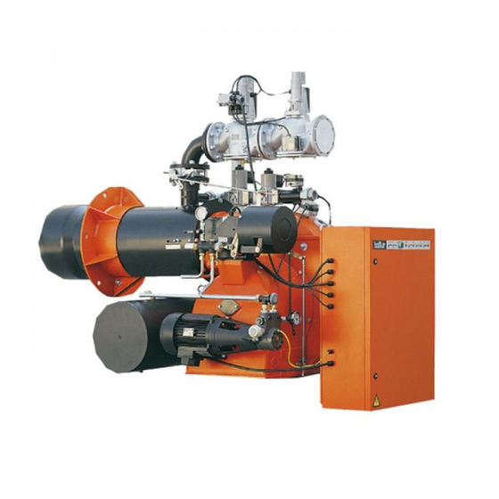
- Page 1 - Instruction for burners model GI MIST 350 DSPGM GI MIST 420 DSPGM GI MIST 510 DSPGM 2005/10 Edition Cod. 0006080103...
- Page 2 CE, CEI and UNI standards. • BALTUR guarantees the “CE” certifi cation provided that the burner is coupled to the “CE” gas train supplied by BALTUR and the “CE” gas line accessories (on request).
- Page 3 INDEX PAGE Technical data “ Gas train assembly diagram - Fastening the burner to the boiler - Electrical connections “ Gas feed system at average pressure “ Fuel feed system (light oil) “ Description of operations two stage progressive with light oil “...
-
Page 4: Technical Data
N° 0002670222 TECHNICAL DATA Rev. 24/10/2005 GI mist 350 DSPGM GI mist 420 DSPGM GI mist 510 DSPGM THERMIC CAPACITY 4743 5522 6500 1581 1840 2430 FLOW RATE m³/h m³/h PRESSURE mbar (In order to obtain the maximum fl ow rate) -
Page 5: Working Field
Ø Ø Ø GI mist 350 DSPGM 1345 660 685 1585 750 835 545 1970 230 355 325 DN65 480 M20 375 GI mist 420 DSPGM 1345 660 685 1530 750 780 490 2030 320 400 355 DN65 520 M20 420... - Page 6 FASTENING THE BURNER TO THE BOILER The burner must be applied to the boiler’s iron plate, where the stud bolts given as standard accessories have already been fi tted in accordance with the plate drilling. It is advisable to electrically weld the stud bolts to the internal part of the plate to avoid extracting them together with the unit’s locking nuts, should the burner disas- sembled.
-
Page 7: Electrical Connections
N° 8807 GAS TRAIN ASSEMBLY DIAGRAM Rev. ELECTRICAL CONNECTIONS The three-phase or single-phase electric supply line of the minimum section, in proportion to the power absorbed by the burner, must be equipped with a fused switch. Furthermore, regulations require a switch on the burner’s feed line which should be located outside the boiler room in an easily accessible position. - Page 8 GAS FEED SYSTEM AT AVERAGE PRESSURE (a few bars) (see BT 8058 - BT 8530/1 - BT 8531/1) When high delivery is required, the Gas Distributing Company requests the installation of a unit comprising a pressure reducer and a meter, and then connects it to the gas pipe network at average pressure (a few bars). This unit can be supplied by the Gas Distributing Company or by the user, but should be according to the Gas Company’s precise instructions.
- Page 9 DIAGRAM OF CONNECTING MORE THAN ONE BURNER TO THE N° 8530-1 Rev. 15/11/90 GAS PIPE NETWORK AT AVERAGE PRESSURE 1 - Measuring and reducing unit 2 - Interception 3 - Filter 4 - Reducer 5 - Meter 6 - Emergency interception (installed outside) 7 - Ball cock 8 - Filter 9 - Final reducer or stabilizer...
- Page 10 FUEL FEED SYSTEM (LIGHT OIL) The burner pump should receive fuel from a feed circuit which has an ancillary pump and, in some cases, a pressure regulator capable of modifying the pressure value 0,2 to 1 bar (see drawing 0002901120). In this case, the value of the fuel feed pressure at the burner pump (0,2 ÷...
- Page 11 N° 8666-3 DIAGRAM OF PIPES OF FEED SYSTEM FOR LIGHT OIL BURNERS OR Rev. HEAVY OIL BURNERS WITH MAXIMUM NOMINAL VISCOSITY 5 °E AT 50 °C 1 - Main tank 2 - Filter 3 - Circulation pump 4 - Water and plant discharge The light oil recovery tanks 5 - Air-gas discharge, normally closed (diameter ~ 150, height ~ 400) should be installed...
- Page 12 These “pins” are pressed against their seats by strong springs which are situated at the opposite ends of the rods. The oil circulates, comes out of the atomizer unit return and arrives at the return pressure regulator. It passes through this and reaches the pump return and from there it is discharged back into the return. Oil circulation, as described above, should be carried out at a pressure value slightly higher (by some bar) than the minimum pressure at which the return pressure regulator has been set (10 ÷...
- Page 13 DESCRIPTION OF MODULATING OPERATIONS WITH LIGHT OIL (See BT 8714/2) The burner’s control box (cyclic relay) is connected by operating panel switch ( I ). Control box specifi cations Control box & Safety Time Pre-Ventilation Post-ignition Time between Pre-ignition relative Pro- in seconds &...
- Page 14 Fuel and combustion air delivery remain at maximum value until the boiler temperature (pressure, if steam boiler), approaches the value at which it has been set and causes the servomotor regulating fuel/air delivery to reverse its previous sense of movement. The return movement of the servomotor causes a gradual reduction in light oil delivery and a relative reduction in combustion air until they reach minimum value.
- Page 15 DIAGRAM OF A DISMANTLED (CB) CHARLES BERGONZO NOZZLE N° 9353/1 Rev. (WITHOUT PIN) N° 0002900580 BALTUR PUMP MODEL BT..Rev. Suction 1/4” Vacuum-meter connection Return Pump plate Delivery (nozzle) Pump pressure 1/4” Pressure gauge connection regulation (20 ÷ 22 bar)
- Page 16 DESCRIPTION OF TWO STAGE PROGRESSIVE OPERATIONS WITH NATURAL GAS (See N° 0002910611) Control box & Pre-Ventilation Pre-ignition Post-ignition Time between Safety Time relative Time with shut- Time Time 1st fl ame & Start of in seconds Programmer ter open in seconds in seconds Modulation in seconds...
- Page 17 DESCRIPTION OF MODULATING OPERATIONS WITH NATURAL GAS FOR (see N° 0002910611) Control box specifi cations Control box & Pre-Ventilation Pre-ignition Post-ignition Time between Safety Time relative Time with shut- Time Time 1st fl ame & Start of in seconds Programmer ter open in seconds in seconds...
- Page 18 DIAGRAM FOR MODULATING OR TWO-STAGE PROGRESSIVE GAS N° 0002910611 Rev. AND DUAL FUEL BURNERS AT NOMINAL THERMAL POWER > 2000 Kw - Minimum and maximum gas pressure switches with - Modulation Servomotor pressure take-off - Defl ector with air and gas supply rate adjuster screws 10 - Gas pressure regulator - Gas supply modulating throttler valve 11 - Filter...
- Page 19 STARTING UP AND REGULATION WITH LIGHT OIL 1) Check that the characteristics of the nozzle (delivery and spray angle) are suitable for the furnace (see BT 9353/1). If not, replace it. 2) Check that there is fuel in the cistern and that it is, at least visually, suitable for the burner. 3) Check that there is water in the boiler and that the system’s gate valves are open.
- Page 20 18) The servomotor which regulates the fuel/air delivery starts moving; wait until the disk on which the regula- ting screws have been fi tted, has reached an angle of about 12° (this corresponds to a space taken up by three screws), stop the modulation and return the switch to the “O” position. Carry out a visual control of the fl...
- Page 21 STARTING UP AND REGULATION WITH METHANE GAS 1) If not already done at the moment of connecting the burner to the gas pipeline, it is indispensable to carry out a purge of the air contained in the pipeline. As a precaution, special care should be taken and doors and windows should be opened.
- Page 22 Note: If gas fl ame detection is carried out with an ionization electrode, the shut down (with fl ame presence) could be caused by fl ame instability in the ionization zone. This fault can be eliminated by operating the combustion head regulator (move it backwards or forwards) until the necessary conditions to ensure fl...
- Page 23 14) With the burner operating at maximum delivery required for the boiler, check combustion with the appropriate instruments and modify, if necessary, the previous regulation carried out after a visual control only (CO max. = 10 % CO max. = 0,1 %). 15) We recommend controlling the combustion with the appropriate instruments and, if necessary, modify the previous regulation carried out, after a visual control only, also in a few intermediate points of the modulation run.
- Page 24 REGULATION OF THE COMBUSTION HEAD AND FLAME DISK (See BT 8608/1) The burner is equipped with a combustion head which can be regulated (by moving it backwards or forwards) in such a way as to close more or open more the air passage between the disk and the head. By closing the passage, it is possible to achieve high pressure upstream the disk and therefore high velo- city and air turbulence for low inputs as well.
- Page 25 READING GAS (METHANE) METER When the burner is operating at maximum output, check that the quantity of gas delivered is necessary for the boiler’s needs. The low calorifi c value for methane gas is about 8550 kcal/m To fi nd out the low calorifi c values of other types of gas, contact the Gas Distributing Company. Delivery per hour should be taken at the meter.
-
Page 26: Maintenance
USE OF THE BURNER The burner operates fully automatically; it is activated by closing the main switch and the control board switch. Burner operations are controlled by command and control devices, as described in the Chapter “Description of Operations” The “shut down” position is a safety position automatically taken up by the burner when a particular part of the burner or of the system is ineffi... - Page 27 INSTRUCTIONS FOR SETTING DUNGS GAS VALVES N° 8875 Rev. 06/11/90 mod. MVD ... and MVDLE ... The MVD gas valves open and close rapidly. Mod. MVD..To regulate the gas fl ow, unscrew and remove cap “A” and loosen nut “B”. Then, using a screwdriver turn screw “C”.
- Page 28 INSTRUCTIONS FOR SETTING LANDIS & GYR mod. SKP 10.110 B27 N° 8880 Rev. 06/11/90 - SKP 10.111B27 SINGLE STAGE GAS VALVES DESCRIPTION OF HOW THE VALVE OPERATES Single-stage valves When the valve receives the signal to open, the pump cuts in and the magnetic valve closes. The pump tran- sfers the oil from under the piston to above it, forcing the piston downward, which compresses the closure return spring with the rod and plate.
- Page 29 INSTRUCTIONS FOR HONEYWELL GAS VALVES UNIVERSAL GAS N° 0002910370 Rev. 25/06/96 VALVES TYPE: VE 4000A1 (..A ..= Opening - Closure, rapid) The VE 4000A1 valves are Class A solenoid valves, normally clo- sed. They may be used as ON/OFF valves in the supply trains with Natural Gas, Manufactured Gas or GPL, on burners or combustion installations.
- Page 30 DETAILS OF THE MODULATION CONTROL MOTOR SQM 10 - SQM 20 N° 8562/1 Rev. FOR REGULATING CAMS OF GAS AND MIXER BURNERS Reference index Cam shaft Adjustable cams Maximum opening end of the run Total air closure (burner at a standstill) Air ignition opening Principle feed valve(s) B = Insertion and disinsertion lever...
- Page 31 N° CONTROL BOX FOR LFL 1... SERIES 02 GAS BURNERS Rev. 10/1997 Control box for burners of average and high power, with forced draught, intermittent service (*), 1 or 2 stages, or modulating types, with supervision of the air pressure for controlling the air damper. This control box bears the EC mark, in accordance with the Gas and Electromagnetic Compatibility Directive.
- Page 32 N° CONTROL BOX FOR LFL 1... SERIES 02 GAS BURNERS Rev. 10/1997 Electrical connections The burner manufacturer’s diagram is valid for the relief valve connections. LEGEND NTC resistor For the entire catalogue sheet QRA.. UV probe Thermostat or pressure probe Limit switch commutation contact for air damper OPEN position Fuel valve with continuous regulation...
- Page 33 N° CONTROL BOX FOR LFL 1... SERIES 02 GAS BURNERS Rev. 10/1997 Notes on the programmer. Programmer sequence Output signals on terminal Times Legend time (50 Hz) in seconds 31.5 ...t1 Pre-ventilation time with air damper open 3 ....t2 Safety time - ....t2’...
- Page 34 N° CONTROL BOX FOR LFL 1... SERIES 02 GAS BURNERS Rev. 10/1997 t2’, t3’, t3’: These times are valid only for series 01 or LFL1.335, LFL1.635, LFL1.638 burner control and command equi- pment. They are not valid for types of Series 032, since they involve simultaneous activation of cams X and VIII. Working The above diagrams illustrate both the connection circuit and the sequencer mechanism control program.
- Page 35 N° CONTROL BOX FOR LFL 1... SERIES 02 GAS BURNERS Rev. 10/1997 Control program in the event of stopping, indicating position of stop As a rule, in the event of any kind of stop, the fuel fl ow is cut off immediately. At the same time, the program- mer remains immobile, as does the switch position indicator.
- Page 36 LDU 11.. GAS VALVE TIGHTNESS CONTROL EQUIPMENT LDU 11 equipment is used to verify tightness of valves on natural gas burners. The LDU 11 combined with a normal pressure switch automatically verifi es tightness of natural gas burners valves, before every start up and immediately after each stop. Tightness control is carried out by two-stage verifi...
- Page 37 LDU 11.. GAS VALVE TIGHTNESS CONTROL EQUIPMENT Control programme Putting control circuit under atmospheric pressure 7,5s Time between start-up and energizing of main “AR” relay 22,5s 1st verifi cation stage at atmospheric pressure Putting control circuit gas under pressure 27,5s 2nd verifi...
- Page 38 NOTES ON USE OF PROPANE (L.P.G.) We think it would be useful to inform you on a few points regarding use of liquid propane gas (L.P.G.). 1) Approximate evaluation of running costs a) 1 m of liquid gas in gaseous state has heating power inferior by about 22.000 Kcal. b) to obtain 1 m of gas about 2 Kg of liquid gas are required.
- Page 39 N° 8721/2 GENERAL DIAGRAM FOR TWO-STAGE L.P.G. PRESSURE Rev. 21/03/1990 REDUCTION FOR BURNER OR BOILER 39 / 61 0006080103 ed2005/10...
- Page 60 BALTUR S.p.A. Via Ferrarese 10 - 44042 CENTO (Ferrara) ITALIA Tel. 051.684.37.11 Fax 051.685.75.27/28 (International Tel. ++39.051.684.37.11 - Fax ++39.051.683.06.86) http://www.baltur.it - http://www.baltur.com E-MAIL info@baltur.it...
Need help?
Do you have a question about the GI MIST 350 DSPGM and is the answer not in the manual?
Questions and answers