Table of Contents
Advertisement
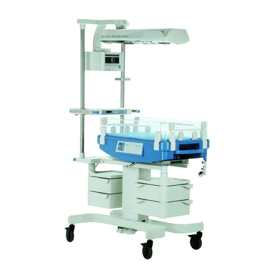
Repair Instructions for Babytherm 8000
Table of contents:
1.
Mechanical system ........................................................................................................... 3
1.1 Trolley ........................................................................................................................... 3
1.2 Column with electrical height adjustment...................................................................... 5
1.3 Base plate for resting surface and accessory rails........................................................ 7
1.4 Socket strip ................................................................................................................... 7
1.5 Resting surface ............................................................................................................. 8
1.6 Accessories................................................................................................................. 14
2.
Pneumatic system .......................................................................................................... 14
2.1 Extraction .................................................................................................................... 14
3.
Heating panel with sensors ............................................................................................ 15
3.1 General information .................................................................................................... 15
3.2 Heating-panel assembly ............................................................................................. 16
3.3 Testing ........................................................................................................................ 18
3.4 Replacement in repair situation .................................................................................. 18
3.5 Testing after replacement ........................................................................................... 19
3.6 Repair information and modification statuses ............................................................. 20
4.
Mattress heating electronics........................................................................................... 22
4.1 Removal and installation of electronics and components ........................................... 22
4.2 Electronics, complete.................................................................................................. 27
4.3 Controller PCB ............................................................................................................ 34
4.4 Power PCB ................................................................................................................. 39
4.5 Display PCB................................................................................................................ 52
4.6 Mains switch ............................................................................................................... 55
4.7 Transformer ................................................................................................................ 56
4.8 Keypad........................................................................................................................ 58
4.9 Mains input ................................................................................................................. 64
4.10 Heating and sensor adapters .................................................................................. 66
5.
Mattress heating software .............................................................................................. 68
5.1 Software versions ....................................................................................................... 68
5.2 Testing after replacement ........................................................................................... 68
6.
Troubleshooting - mattress heating ................................................................................ 69
6132.200
Babytherm 8000
Repair Instructions
04.01
Page 1 of 115
Advertisement
Table of Contents
Troubleshooting

Related Manuals for Dräger Babytherm 8000


Summary of Contents for Dräger Babytherm 8000
-
Page 1: Table Of Contents
Repair Instructions for Babytherm 8000 Table of contents: Mechanical system ......................3 1.1 Trolley ........................... 3 1.2 Column with electrical height adjustment..............5 1.3 Base plate for resting surface and accessory rails............7 1.4 Socket strip ........................7 1.5 Resting surface ......................8 1.6 Accessories......................... - Page 2 9.2 Mounting the mechanics of the resting-surface tilt-mechanism (09.94)....109 9.3 Alteration of class type B to BF (12.94) ..............109 9.4 Additional height adjustment extra high (02.95)............115 9.5 Castors of non-height-adjustable units (03.95) ............115 Repair Instructions 6132.200 Babytherm 8000 04.01 Page 2 of 115...
-
Page 3: Mechanical System
Mechanical system Trolley The Babytherm 8000 is available with various trolleys: Units with no electrical height adjustment: Small base plate for heated cot Large base plate for intensive-care model or reanimation unit. This version permits installation of a radiant heater. - Page 4 2M 21 174 (must nor be used on the Heated Cot with the short trolley 2M 21 038) Height adjustment 115V 2M 20 946 Height adjustment 110V (extra high) 2M 21 175 Repair Instructions 6132.200 Babytherm 8000 04.01 Page 4 of 115...
-
Page 5: Column With Electrical Height Adjustment
2M 20 940 Height adjustment 230V (extra high) 2M 21 174 (must nor be used on the Heated Cot with the short trolley 2M 21 038) Height adjustment 115V 2M 20 946 Repair Instructions 6132.200 Babytherm 8000 04.01 Page 5 of 115... - Page 6 Height adjustment 115V: Dynamic force: 750 N Stroke: 295 mm Speed: 12 - 15 mm/s Voltage: 100 - 127 V / 50/60 Hz Current consumption: < 0.1 mA Leakage current: Fuses: Repair Instructions 6132.200 Babytherm 8000 04.01 Page 6 of 115...
-
Page 7: Base Plate For Resting Surface And Accessory Rails
Replacement parts are available in line with the spare parts list. Base plate for resting surface and accessory rails The resting surface is attached to the base plate. The Babytherm 8000 comes with various base plates: Small base plate and small trolley for heated cot... -
Page 8: Resting Surface
Floating) must be used. The units are currently being supplied as type B (Body) i.e. with earthed resting surface. Production of the Babytherm 8000 with mattress heating is to be switched as of the start of 1995 to class type Typ BF; prior to this date roughly 300 units will be delivered with the old class type B. - Page 9 40 °C ⇒ danger of burns! Keep sharp objects away from gel mattress ⇒ danger of damage! Without mattress heating: Foam mattress 2M 21 012 Babytherm 8000 dummy panel 2M 21 067 Repair Instructions 6132.200 Babytherm 8000 04.01...
- Page 10 Pull out lever A approximately half way (20 mm): ⇒ Resting surface remains fixed in every position Pull out lever A to 3/4 of overall distance (30 mm): ⇒ Resting surface can be silently adjusted Repair Instructions 6132.200 Babytherm 8000 04.01 Page 10 of 115...
- Page 11 Presence of and check on the two return springs 83 00 445 ⇒ Spring force must be sufficient to reliably return lever to initial position. Pull out lever A approximately half way (20 mm): Repair Instructions 6132.200 Babytherm 8000 04.01 Page 11 of 115...
- Page 12 Apply epoxy hardening glue (UHU Plus, order no. 11 95 255) on the threads of the bolts E and F. Screw in the bolts E and F and re- tighten them. Repeat the test. Reattach resting surface Electrical safety check Repair Instructions 6132.200 Babytherm 8000 04.01 Page 12 of 115...
- Page 13 Visually inspect correct installation of all parts Check resting-surface tilt mechanism (see 1.5.2.1) If heating or electronics assembly has been removed: Electrical safety check Functional check (Test time at least 20 minutes) • Heating function Repair Instructions 6132.200 Babytherm 8000 04.01 Page 13 of 115...
-
Page 14: Accessories
Cabinet mount, complete 2M 20 868 Swivel cabinet 2M 20 638 1.6.2 Rail for resting-surface Modification kit rail 2M 21 468 Pneumatic system Extraction The extraction is not part of this documentation. Repair Instructions 6132.200 Babytherm 8000 04.01 Page 14 of 115... -
Page 15: Heating Panel With Sensors
As not all parts of the mattress heating are interchangeable, the modified components have new order numbers. Always pay attention to repair information when performing repairs. The heating panel is only intended for the gel mattress 2M 20 827 Repair Instructions 6132.200 Babytherm 8000 04.01 Page 15 of 115... -
Page 16: Heating-Panel Assembly
Danger: The gel mattress 2M 20 827 may only be used in the Babytherm 8000 in conjunction with the resting-surface heater! The gel mattress 2M 20 827 is not to be used in the Babytherm 4200 and in other heated cots with a heating-panel temperature in excess of 40 °C ⇒... - Page 17 Sensor 1, second half Module 3 black Sensor 2, second half Module 4 white Sensor 2, second half Module 4 There is no preferential position for the two halves on the backing plate. Repair Instructions 6132.200 Babytherm 8000 04.01 Page 17 of 115...
-
Page 18: Testing
Heating-panel assembly 2M 20 877 Twin temperature sensor 2M 20 859 Backing-plate seal 2M 20 882 For type BF: Heating-panel assembly 2M 21 510 Twin temperature sensor 2M 20 859 Repair Instructions 6132.200 Babytherm 8000 04.01 Page 18 of 115... -
Page 19: Testing After Replacement
Proper connection of heating to electronics assembly Correct installation of electronics assembly Functional check (Test duration at least 30 minutes): Adjust setpoint to 37.0 °C. If setpoint higher than actual value: ⇒ Heating LED flashes Repair Instructions 6132.200 Babytherm 8000 04.01 Page 19 of 115... -
Page 20: Repair Information And Modification Statuses
Floating) must be used. The units are currently being supplied as type B (Body) i.e. with earthed resting surface. Production of the Babytherm 8000 with mattress heating is to be switched as of the start of 1995 to class type Typ BF; prior to this date roughly 300 units will be delivered with the old class type B. - Page 21 (with metal tube) with a tube ID of approx. 2.6 mm. Important: A summary of class alteration from type B to BF is given in Section 9.3. Consult this Section in the event of doubt. Repair Instructions 6132.200 Babytherm 8000 04.01 Page 21 of 115...
-
Page 22: Mattress Heating Electronics
- 2. Pull electronics assembly slightly out of Babytherm 1. (2x) - 3. Detach mains connection - 4. Detach sensor and heating connecting cable - 5. Pull out electronics assembly - Install in reverse order Repair Instructions 6132.200 Babytherm 8000 04.01 Page 22 of 115... - Page 23 Detach cable connections from connectors in cover to printed circuit cards. Bend housing apart on side (1.) and tilt keypad with display PCB forwards (2.). Transformer PCB Power PCB Controller PCB Display Keyboard Install in reverse order. Repair Instructions 6132.200 Babytherm 8000 04.01 Page 23 of 115...
- Page 24 RS232 Sensors PCB Display Keyboard Switch Important: 100 - 127 V units feature a voltage adapter from the accessory set: voltage conversion 2M 21 176 between mains switch and transformer. Repair Instructions 6132.200 Babytherm 8000 04.01 Page 24 of 115...
- Page 25 Removal of the controller PCB may involve removal of the snap fasteners for the power PCB. To do so, squeeze snap fasteners Repair Instructions 6132.200 Babytherm 8000 04.01 Page 25 of 115...
- Page 26 Detach cable connections at mains input (see 4.1.3 wiring diagram) Mains input is attached to housing with two screw connections Install in reverse order 4.1.7 Transformer, adapter for mains voltage conversion 100 - 127 V Repair Instructions 6132.200 Babytherm 8000 04.01 Page 26 of 115...
-
Page 27: Electronics, Complete
The repair information for these individual components is given in sections 4.3 - 4.2.2 Voltage conversion As the heating is driven via the transformer, the mains voltage is no problem to convert. Repair Instructions 6132.200 Babytherm 8000 04.01 Page 27 of 115... - Page 28 All displays and horn are actuated for 2 s. All displays and horn then off for 2 s. This is followed by return to original display. If setpoint higher than actual value: Repair Instructions 6132.200 Babytherm 8000 04.01 Page 28 of 115...
- Page 29 0.4 °C. Note: The value displayed in DS mode is 1.0 °C higher than the value normally displayed in operation. Instead of sensors, connect up Babytherm 8000 test plug (35 °C + 1 °C Offset) 79 00 965. Testing in DS mode, see 6.1: Read out all four temperature values in each case in DS mode.
- Page 30 The following tests are to be performed after replacement of the electronics assembly: Visual checks: Correct mains voltage set in electronics assembly (see 4.2.3). Electrical safety check Functional test (Test duration at least 20 minutes) Function of heating Repair Instructions 6132.200 Babytherm 8000 04.01 Page 30 of 115...
- Page 31 Mains failure alarm Data storage with mains failure alarm Function of keys Function of display elements No error messages Repair Instructions 6132.200 Babytherm 8000 04.01 Page 31 of 115...
- Page 32 Floating) must be used. The units are currently being supplied as type B (Body) i.e. with earthed resting surface. Production of the Babytherm 8000 with mattress heating is to be switched as of the start of 1995 to class type Typ BF; prior to this date roughly 300 units will be delivered with the old class type B.
- Page 33 Important: A summary of class alteration from type B to BF is given in Section 9.3. Consult this Section in the event of doubt. Repair Instructions 6132.200 Babytherm 8000 04.01 Page 33 of 115...
-
Page 34: Controller Pcb
PCB Power + PCB Controller Transformer Mains input with fuses Connection heating PCB Power Horn Gold Cap Relay Fuses Test points PCB Controller Connection EPROM Sensors 4 Service-LEDs Switch PCB Display Keyboard Repair Instructions 6132.200 Babytherm 8000 04.01 Page 34 of 115... - Page 35 RS232 Sensors Components and jumpers: Item Component/function Connection to display PCB Connection to power PCB Connection to sensors of heating panel; refer to 3.2.1 for wiring diagram RS232 (not active) Repair Instructions 6132.200 Babytherm 8000 04.01 Page 35 of 115...
- Page 36 3 keys pressed = 3 LEDs flash Processor ok Processor ok V1 V2 V3 V4 Important: There are no components on the controller PCB which have to be replaced at service intervals. Repair Instructions 6132.200 Babytherm 8000 04.01 Page 36 of 115...
- Page 37 Floating) must be used. The units are currently being supplied as type B (Body) i.e. with earthed resting surface. Production of the Babytherm 8000 with mattress heating is to be switched as of the start of 1995 to class type Typ BF; prior to this date roughly 300 units will be delivered with the old class type B.
- Page 38 1.04. If a new Controller PCB is used with the previous software version error code 15 will be generated. When replacing the Controller PCB P/N 8290668, software version 1.04 (P/N 2M22467) must be installed. Repair Instructions 6132.200 Babytherm 8000 04.01 Page 38 of 115...
-
Page 39: Power Pcb
PCB Power + PCB Controller Transformer Mains input with fuses Connection heating PCB Power Horn Gold Cap Relay Fuses Test points PCB Controller Connection EPROM Sensors 4 Service-LEDs Switch PCB Display Keyboard Repair Instructions 6132.200 Babytherm 8000 04.01 Page 39 of 115... - Page 40 3 = Voltage, gold cap (battery) 4 = not used 5 = not used 6 = not used Connection, heating: 1 and 2 = Heating 3 = Protective conductor, heating panel Repair Instructions 6132.200 Babytherm 8000 04.01 Page 40 of 115...
- Page 41 18 24 880 Important: There are no components on the power PCB which have to be replaced at service intervals. 4.4.3 Testing power PCB 4.4.3.1 Supply voltages Preparation for testing: Repair Instructions 6132.200 Babytherm 8000 04.01 Page 41 of 115...
- Page 42 Remove cover from electronics assembly Heating and sensors do not have to be connected Establish mains connection Caution: Parts under current (e. g. mains switch) may be touched by coincidance, therefore use insulation transformer. Repair Instructions 6132.200 Babytherm 8000 04.01 Page 42 of 115...
- Page 43 F1 = Fuse for 24 V AC - Voltage F2 = Fuse for 5 V - Voltages 9 V AC Fuses 24 V AC PCB Power Test points GND digital + 5 V digital Batt.-Volt. Testing: Repair Instructions 6132.200 Babytherm 8000 04.01 Page 43 of 115...
- Page 44 PCB. Connect up Uni test board, complete 79 00 610 with 40-pin ribbon cable to power PCB. Connect up heating on power PCB. Establish mains connection: Repair Instructions 6132.200 Babytherm 8000 04.01 Page 44 of 115...
- Page 45 PCB Power Horn Relay Test points LP Controller EPROM 4 Service-LEDs PCB Display Dräger Testboard Uni 79 00 620 free 5 VD Heating on Relay on Feedback heating GNDD Repair Instructions 6132.200 Babytherm 8000 04.01 Page 45 of 115...
- Page 46 Interrupt ribbon cable connection between power PCB and controller PCB; this involves disconnecting power PCB. Connect up Uni test board complete 79 00 610 with 40-pin ribbon cable to power PCB. Establish mains connection. Repair Instructions 6132.200 Babytherm 8000 04.01 Page 46 of 115...
- Page 47 Test set-up and measurement points: Connection heating PCBPower Horn Relay Fuses Test points PCB Controller EPROM 4 Service-LEDs Switch PCB Display Tastatur Dräger Testboard Uni 79 00 620 free Repair Instructions 6132.200 Babytherm 8000 04.01 Page 47 of 115...
- Page 48 + 5V defective - Charging circuit for gold cap C25 defective - Switch defective V ≈ 0 V Testing horn and mains failure recognition: Prerequisite: Mains-switch auxiliary contacts OK Repair Instructions 6132.200 Babytherm 8000 04.01 Page 48 of 115...
- Page 49 Test set-up and measurement points: Connection heating PCB Power Horn Relay Fuses Test points PCB Controller EPROM 4 Service-LEDs Switch PCB Display Dräger Testboard Uni 79 00 620 free Horn on Horn off Repair Instructions 6132.200 Babytherm 8000 04.01 Page 49 of 115...
- Page 50 The following spare parts are available for repairs: Power PCB, complete (see TSB # 4 or IDM # 5) 82 90 771 Relay 5V / 8A 18 37 001 Fuse T 800 mA 18 15 075 Repair Instructions 6132.200 Babytherm 8000 04.01 Page 50 of 115...
- Page 51 Functional check (Test duration at least 20 minutes) Function of heating Mains failure alarm Data storage with mains failure alarm Function of keys Function of display elements No error messages Repair Instructions 6132.200 Babytherm 8000 04.01 Page 51 of 115...
-
Page 52: Display Pcb
LEDs on the controller PCB. Important: a jumper on the controller PCB X12 at position 1-2 (call-up of DS mode without keys) is classed as a key being pressed (refer also to 4.3.3). Repair Instructions 6132.200 Babytherm 8000 04.01 Page 52 of 115... - Page 53 All LEDs (and horn) are actuated for one second; "88.8" appears on the 7-segment displays. Possible faults: Display Possible faults - Display PCB defective LEDs "40°C", "±1°C", ">37°C/<35°C" and "horn off" defective (off or flash); 7-segment displays not OK Repair Instructions 6132.200 Babytherm 8000 04.01 Page 53 of 115...
- Page 54 Display PCB correctly installed Electrical safety check Functional check: Test duration at least 20 minutes Function of keys Function of displays Mains failure alarm Data storage with mains failure alarm No error messages Repair Instructions 6132.200 Babytherm 8000 04.01 Page 54 of 115...
-
Page 55: Mains Switch
Knob for mains switch 83 02 369 4.6.5 Testing after replacement The following tests are to be performed after replacing the keypad: Visual checks Mains switch correctly installed (see also 4.1.3 Wiring diagram) Repair Instructions 6132.200 Babytherm 8000 04.01 Page 55 of 115... -
Page 56: Transformer
2 x 100 V 2 x 120 V Output, secondary: 24 V / 6.7 A with centre tap 9 V Frequency: 50 / 60 Hz Ambient temperature: max. 45 °C Limit temperature: Repair Instructions 6132.200 Babytherm 8000 04.01 Page 56 of 115... - Page 57 Testing after replacement The following tests are to be performed after replacing the keypad: Visual checks Transformer correctly installed (see also 4.1.3 Wiring diagram) Test output voltages of transformer Electrical safety check Repair Instructions 6132.200 Babytherm 8000 04.01 Page 57 of 115...
-
Page 58: Keypad
Function of keys Function of displays Mains failure alarm Data storage with mains failure alarm • No error messages Keypad 4.8.1 General information The keypad contains: 5 touch-sensitive keys 6 LEDs Repair Instructions 6132.200 Babytherm 8000 04.01 Page 58 of 115... - Page 59 4.8.2 Keypad 2M 20 885 Layout: Components and function: Compone Function Touch-sensitive key ">37°C/<35°C" read in by display Touch-sensitive key "negative setpoint" read in by display PCB Repair Instructions 6132.200 Babytherm 8000 04.01 Page 59 of 115...
- Page 60 LED "Inop.", red, actuated by controller PCB LED "power failure", red, actuated by power PCB LED ">37°C/<35°C", yellow, actuated by display PCB LED "horn off", yellow, actuated by display PCB The keypad cannot be repaired. Repair Instructions 6132.200 Babytherm 8000 04.01 Page 60 of 115...
- Page 61 1 key pressed = 1 LED flashes RAM defective 2 keys pressed = 2 LEDs flash PCB Display INOP 3 keys pressed = 3 LEDs flash Processor ok Processor ok V1 V2 V3 V4 Repair Instructions 6132.200 Babytherm 8000 04.01 Page 61 of 115...
- Page 62 - Actuation transistor on power PCB defective LED "horn off" and horn off - Power PCB defective LED "Inop." off - Keypad defective (LED defective or cable break) - Controller PCB defective (actuation) Repair Instructions 6132.200 Babytherm 8000 04.01 Page 62 of 115...
- Page 63 "+" is fed in in each case at the anodes of the LEDs (pins 14, 15, 16, 17, 18 or 22). Repair Instructions 6132.200 Babytherm 8000 04.01 Page 63 of 115...
-
Page 64: Mains Input
Data storage with mains failure alarm No error messages Mains input 4.9.1 General information The mains-input assembly features the following functions: Power cord connector Accommodation of both mains fuses Mains filter Repair Instructions 6132.200 Babytherm 8000 04.01 Page 64 of 115... - Page 65 Electrical safety check: Functional check (Test duration at least 20 minutes) Function of keys Function of display elements Mains failure alarm Data storage with mains failure alarm No error messages Repair Instructions 6132.200 Babytherm 8000 04.01 Page 65 of 115...
-
Page 66: Heating And Sensor Adapters
Floating) must be used. The units are currently being supplied as type B (Body) i.e. with earthed resting surface. Production of the Babytherm 8000 with mattress heating is to be switched as of the start of 1995 to class type Typ BF; prior to this date roughly 300 units will be delivered with the old class type B. - Page 67 This cable can also be used in type Important: A summary of class alteration from type B to BF is given in Section 9.3. Consult this Section in the event of doubt. Repair Instructions 6132.200 Babytherm 8000 04.01 Page 67 of 115...
-
Page 68: Mattress Heating Software
Software 1.02 mattress heating no longer available Software 1.04 mattress heating 2M 22 467 Testing after replacement See 4.2, however not including test with Babytherm 8000 test plug. Repair Instructions 6132.200 Babytherm 8000 04.01 Page 68 of 115... -
Page 69: Troubleshooting - Mattress Heating
Readout of all A/D converter channels and mono-times Actuation of safety relay and heating 4 Service LEDs on Controller PCB One LED indicates status of processor Three LEDs are assigned various functions depending on operating status Repair Instructions 6132.200 Babytherm 8000 04.01 Page 69 of 115... -
Page 70: Usage Instructions For Ds Mode
Important: Error message after 30 s with sustained short circuit. Position in normal operation without jumper or jumper in park position 2-3: Call-up of service mode. Short circuit for max. 30 seconds between 1-2: Repair Instructions 6132.200 Babytherm 8000 04.01 Page 70 of 115... - Page 71 It is possible to exit from service mode at any time by: jointly pressing the keys "horn off" and "negative temp." for more than 2 s or by switching off the unit Repair Instructions 6132.200 Babytherm 8000 04.01 Page 71 of 115...
-
Page 72: Diagnosis Mode
6.3.C Mode C Switch-on and switch-off, heating and readout of heating status feedback 6.3.d Mode d Position of mains switch 6.3.E Mode E Readout and setting of elapsed time meter Repair Instructions 6132.200 Babytherm 8000 04.01 Page 72 of 115... - Page 73 Temperature in °C without 1.0 °C offset subtracted during operation Switching status, excess temperature comparator No excess temperature Excess temperature detected Press key "check": Display A B , C = 41.6 ± 0.2 °C and D = 1 Repair Instructions 6132.200 Babytherm 8000 04.01 Page 73 of 115...
- Page 74 "ANASW2" and readout of switching status of excess temperature comparator (UETEMPQ). A B C D E F 37°C Horn Check 35°C Mode number 3 flashing A B , C Temperature in °C without 1.0 °C offset subtracted during operation Repair Instructions 6132.200 Babytherm 8000 04.01 Page 74 of 115...
- Page 75 Mode number 4 flashing A B , C Temperature in °C without 1.0 °C offset subtracted during operation Mode number can be switched with the keys "positive temp." or "negative temp.". Back Repair Instructions 6132.200 Babytherm 8000 04.01 Page 75 of 115...
- Page 76 Gold cap voltage with charging voltage (D = 1): ≥ A ; B C 3.5 V Gold cap voltage without charging voltage (D = 0); to do so press key "check": Repair Instructions 6132.200 Babytherm 8000 04.01 Page 76 of 115...
- Page 77 A/D converter; it corresponds to the voltage of 0.39 ± 0.02 V at the input of the A/D converter. Mode number can be switched with the keys "positive temp." or "negative temp.". Back Repair Instructions 6132.200 Babytherm 8000 04.01 Page 77 of 115...
- Page 78 Mode number A flashing Mono-time in ms, set value = 250 ± 3 ms A B C Mode number can be switched with the keys "positive temp." or "negative temp.". Back Repair Instructions 6132.200 Babytherm 8000 04.01 Page 78 of 115...
- Page 79 Mode for switching on and switching off heating and readout of heating status feedback A B C D E F 37°C Horn Check 35°C Mode number C flashing Repair Instructions 6132.200 Babytherm 8000 04.01 Page 79 of 115...
- Page 80 A B C D E F 37°C Horn Check 35°C Mode number d flashing A B C P F S as flag for power fail switch Position of mains-switch auxiliary contacts Repair Instructions 6132.200 Babytherm 8000 04.01 Page 80 of 115...
- Page 81 Key "horn off" Selection of digit A, B, C, D or E ⇒ Key "check" Change digit Mode number can be switched with the keys "positive temp." or "negative temp.". Back Repair Instructions 6132.200 Babytherm 8000 04.01 Page 81 of 115...
-
Page 82: Troubleshooting And Error List
INOP in self-test Description: Unit switches to INOP after switch-on in self-test Cause: Stored in error list or indicated by service LEDs on controller PCB Troubleshooting: Test voltage supply (see 4.4.3.1) Repair Instructions 6132.200 Babytherm 8000 04.01 Page 82 of 115... - Page 83 Modules for displays behind keypad and display driver on display PCB defective Permanent mains failure Power cord not correctly connected Mains input fuses defective (see 4.9) Fuse F2 for 5V supply on controller PCB Repair Instructions 6132.200 Babytherm 8000 04.01 Page 83 of 115...
- Page 84 (see 4.4.2) Repair Instructions 6132.200 Babytherm 8000 04.01 Page 84 of 115...
- Page 85 1 key pressed = 1 LED flashes RAM defective 2 keys pressed = 2 LEDs flash PCB Display INOP 3 keys pressed = 3 LEDs flash Processor ok Processor ok V1 V2 V3 V4 Repair Instructions 6132.200 Babytherm 8000 04.01 Page 85 of 115...
- Page 86 LED 1 - 3 Keypad test: One key pressed: ⇒ Only one LED flashes Two keys pressed: ⇒ Two LEDs flash Three or more keys pressed: ⇒ Three LEDs flash Repair Instructions 6132.200 Babytherm 8000 04.01 Page 86 of 115...
- Page 87 Err22 Err23 Err24 Err25 Err30 Err31 Err32 Err50 Err51 Err53 Err57 Err58 Err59 Err60 Err61 Err70 Err80 Err81 Err82 Err83 Err84 Err85 Err86 Err87 Err88 Err89 Err90 Err91 Err92 Err93 Repair Instructions 6132.200 Babytherm 8000 04.01 Page 87 of 115...
- Page 88 RAM on controller PCB defective Error recognition: RAM test in self-test unsuccessful Cause: - RAM on controller PCB defective - Controller PCB defective Remedy: Renew controller PCB (see 4.3) Back Repair Instructions 6132.200 Babytherm 8000 04.01 Page 88 of 115...
- Page 89 EEPROM error on controller PCB Error recognition: EEPROM test unsuccessful Cause: - EEPROM on controller PCB defective - Controller PCB defective - Wrong software version, see TSB Babytherm 8000 # 11 Remedy: Renew controller PCB (see 4.3) or software version. Back Repair Instructions 6132.200 Babytherm 8000 04.01...
- Page 90 Input of temperature channel 1 (Vin0) is switched to test resistor 41.6 °C during test; resultant measured value is outside tolerance. Troubleshooting: See 6.2.1 Diagnosis mode 1 Cause: Controller PCB defective Remedy: Renew controller PCB (see 4.3) Back Repair Instructions 6132.200 Babytherm 8000 04.01 Page 90 of 115...
- Page 91 Input of temperature channel 3 (Vin2) is switched to test resistor 41.6 °C during test, however excess temperature comparator has not switched. Troubleshooting: See 6.2.3 Diagnosis mode 3 Cause: Controller PCB defective Remedy: Renew controller PCB (see 4.3) Back Repair Instructions 6132.200 Babytherm 8000 04.01 Page 91 of 115...
- Page 92 - Activation/deactivation of charging voltage on controller PCB defective Remedy: If all other A/D channels functioning: 1) Renew power PCB (see 4.4) 2) If 1) unsuccessful: renew controller PCB (see 4.3) Back Repair Instructions 6132.200 Babytherm 8000 04.01 Page 92 of 115...
- Page 93 - Read-in of check-back signal on Controller PCB defective Remedy: 1) Renew Power PCB or Relay K1 on Power PCB (see 4.4) 2) If 1) unsuccessful: renew Controller PCB (see 4.3) Back Repair Instructions 6132.200 Babytherm 8000 04.01 Page 93 of 115...
- Page 94 ⇒ Check-back signal = heating off = Relay OK Without diagnosis mode: See 4.4.3.2 Remedy: 1) Renew power PCB (see 4.4) 2) If 1) unsuccessful: renew controller PCB (see 4.3) Back Repair Instructions 6132.200 Babytherm 8000 04.01 Page 94 of 115...
- Page 95 - Display PCB defective - Controller PCB defective Remedy: 1) Renew display PCB or D1 on display PCB (see 4.5) 2) If 1) unsuccessful: renew controller PCB (see 4.3) Back Repair Instructions 6132.200 Babytherm 8000 04.01 Page 95 of 115...
- Page 96 Cause: - Key on keypad defective - Display PCB defective Remedy: 1) If other keys function: renew keypad (see 4.8) 2) If 1) unsuccessful: renew display PCB (see 4.5) Back Repair Instructions 6132.200 Babytherm 8000 04.01 Page 96 of 115...
- Page 97 Cause: - Key on keypad defective - Display PCB defective Remedy: 1) If other keys function: renew keypad (see 4.8) 2) If 1) unsuccessful: renew display PCB (see 4.5) Back Repair Instructions 6132.200 Babytherm 8000 04.01 Page 97 of 115...
- Page 98 - Heating high impedance - Power PCB defective Troubleshooting: - Heating connected? - Measure heating resistance approx. R = 4.8 ohms Remedy: If heating OK, renew power PCB (see 4.4) Back Repair Instructions 6132.200 Babytherm 8000 04.01 Page 98 of 115...
- Page 99 - Cable connection between controller PCB and connector on cover of electronics assembly defective - Temperature measurement on controller PCB defective (Vin 1) Troubleshooting: - Test sensors (see 3.2.1) - Test controller PCB (see 4.3) Back Repair Instructions 6132.200 Babytherm 8000 04.01 Page 99 of 115...
- Page 100 - Cable connection between controller PCB and connector on cover of electronics assembly defective - Temperature measurement on controller PCB defective (Vin 3) Troubleshooting: - Test sensors (see 3.2.1) - Test controller PCB (see 4.3) Back Repair Instructions 6132.200 Babytherm 8000 04.01 Page 100 of 115...
- Page 101 - Cable connection between controller PCB and connector on cover of electronics assembly defective - Temperature measurement on controller PCB defective (Vin 1) Troubleshooting: - Test sensors (see 3.2.1) - Test controller PCB (see 4.3) Back Repair Instructions 6132.200 Babytherm 8000 04.01 Page 101 of 115...
- Page 102 - Cable connection between controller PCB and connector on cover of electronics assembly defective - Temperature measurement on controller PCB defective (Vin 3) Troubleshooting: - Test sensors (see 3.2.1) - Test controller PCB (see 4.3) Back Repair Instructions 6132.200 Babytherm 8000 04.01 Page 102 of 115...
- Page 103 (Vin1) at joint measurement location (first half) more than 0.5 °C. Cause: - Measurement electronics on controller PCB defective - Sensors defective Troubleshooting: See 4.2 Remedy: Depending on cause Back Repair Instructions 6132.200 Babytherm 8000 04.01 Page 103 of 115...
- Page 104 - Cold object on one half of heating panel - Heating defective (one half) Troubleshooting: - Measure heating resistance approx. R = 4.8 ohms - Cold object on heating Remedy: Depending on cause Back Repair Instructions 6132.200 Babytherm 8000 04.01 Page 104 of 115...
- Page 105 Excess temperature shutdown 41.6 °C tripped Error recognition: Temperature of more than 41.6 °C, mandatory shutdown of heating Cause: - External heat source - Heating actuation defective Troubleshooting: See 4.2 Remedy: Depending on cause Back Repair Instructions 6132.200 Babytherm 8000 04.01 Page 105 of 115...
-
Page 106: 10-Minute Test
Readout errors with key " ⇑ " and " ⇓ ". Radiant heater 600W The radiant heater 600 W is not part of this documentation; the radiant heater has its own service documentation. Repair Instructions 6132.200 Babytherm 8000 04.01 Page 106 of 115... -
Page 107: List Of Test Equipment And Tools
List of test equipment and tools The following test equipment and tools is/are required for repair work: Primarily for work on electrical components Babytherm 8000 test plug 79 01 965 (35.0 °C + offset) Uni test board with cable set... -
Page 108: Equipment For Functional Tests
1.00 and 1.01 used in the test devices are no longer valid. Software 1.00/1.01 Babytherm mattress heating not valid Software 1.02 Babytherm mattress heating 82 90 673 See also Chapter 5.1. Repair Instructions 6132.200 Babytherm 8000 04.01 Page 108 of 115... -
Page 109: Mounting The Mechanics Of The Resting-Surface Tilt-Mechanism (09.94)
Floating) must be used. The units are currently being supplied as type B (Body) i.e. with earthed resting surface. Production of the Babytherm 8000 with mattress heating is to be switched as of the start of 1995 to class type Typ BF; prior to this date roughly 300 units will be delivered with the old class type B. - Page 110 Important: Differentiation is also possible by way of a mark on the control unit for the mattress heating. Newer control units for type BF feature a stamped mark on the underside, i.e. readily legible even when installed. Repair Instructions 6132.200 Babytherm 8000 04.01 Page 110 of 115...
- Page 111 "Extractor for crimp socket 2.6 mm" with the order no. 79 01 120; another possibility is to make use of ballpoint-pen refills (with metal tube) with a tube ID of approx. 2.6 mm. Repair Instructions 6132.200 Babytherm 8000 04.01 Page 111 of 115...
- Page 112 Wiring harness without ferrite between sensor connection on between sensor connection on housing cover and controller PCB. housing cover and controller PCB This cable can also be used in type Repair Instructions 6132.200 Babytherm 8000 04.01 Page 112 of 115...
- Page 113 9.3.4.4 Operating instructions There are different operating instructions for types B and BF. Type B Type BF Joint operating instructions for Babytherm 8000 WB (Heated Babytherm 8000 WB (Heated cot/Resuscitation Unit)): Cot/Resuscitation Unit) and - German 90 28 323 Babytherm 8000 OC (Resuscitation...
- Page 114 Only for use in type B. Can be used in types B and BF Use in type BF could lead to destruction of sensor input caused by the influence of voltage peaks Repair Instructions 6132.200 Babytherm 8000 04.01 Page 114 of 115...
-
Page 115: Additional Height Adjustment Extra High (02.95)
64mm (= 2.5 inch) higher than the normal one. This extra high height adjustment must not be used on the Heated Cot Babytherm 8000 WB with the short trolley. For further details, refer to Chapters 1.1.2 und 1.2.
Need help?
Do you have a question about the Babytherm 8000 and is the answer not in the manual?
Questions and answers