Table of Contents
Advertisement
Quick Links
Advertisement
Table of Contents

Subscribe to Our Youtube Channel
Related Manuals for LifeSize Gateway-PRI


Summary of Contents for LifeSize Gateway-PRI
- Page 1 LifeSize Gateway ™ User Guide...
- Page 2 LifeSize Communications. Trademark Acknowledgments LifeSize is the trademark of LifeSize Communications, Inc. All other trademarks are the property of their respective owners. Contacting Customer Support If you have questions, concerns, or need assistance, contact your LifeSize Channel Partner.
-
Page 3: Table Of Contents
1 1 1 1 Functionality About LifeSize Gateway Products About the Gateway-PRI About the Gateway-Serial About Gateway Features About LifeSize Gateway Applications and Topologies About Multimedia Conferencing About Point-to-Point Conferencing About Multipoint Conferencing About Gateway IP Network Connections About Gateway ISDN Network Connections... - Page 4 Mounting the LifeSize Gateway Unit in a 19-inch Rack LifeSize Gateway Unit Initial Configuration Connecting to a PC Setting the IP Address Changing the Configuration Tool Login Password Connecting the LifeSize Gateway Unit to the LAN Connecting Serial Lines to the Gateway...
- Page 5 Changing Address Settings Changing the Administrator Interface Web Server Port Configuring Security About the Gateway Administrator Interface Viewing the Status Tab Viewing B Channel Status Refreshing Gateway Status Configuring Gateway Settings Configuring Basic Gateway Settings Configuring IP Connectivity Settings Configuring IVR Settings Configuring Outgoing Call Delimiters About Encoding/Decoding Protocols Configuring Encoding/Decoding Protocols...
- Page 6 Accessing Device Commands through the Serial Port Changing a Global User Name and Password Setting Echo Cancellation Configuring the Web Server Port Setting T.120 Data Collaboration Capability Restoring the Factory Default Settings Configuring the Ethernet Port vi LifeSize Gateway User Guide...
- Page 7 6 6 6 6 Using the LifeSize Audio Message Utility Introduction About Gateway Call Routing Launching the Utility Playing a Message LifeSize Gateway Messages Recording a Message Replacing a Message Uploading a Message to a Device Viewing Message Details Exiting the Utility...
- Page 8 LifeSize Gateway User Guide...
-
Page 9: Functionality
UNCTIONALITY This section introduces the LifeSize Gateways, and includes the following topics: About LifeSize Gateway Products About Gateway Features About LifeSize Gateway Applications and Topologies About LifeSize Gateway Functionality BOUT LifeSize Gateway consists of the following products: ATEWAY Gateway-PRI (see... -
Page 10: About Gateway Features
About Gateway Features The LifeSize Gateway offers a serial leg for multimedia conferencing over IP by providing an interface for legacy endpoints with serial interfaces, encryption/decryption devices, satellite networks and leased line services. BOUT ATEWAY Table 1-1 lists the major features of the LifeSize Gateways. - Page 11 IP endpoint and sets the same bit rate for the ISDN (or serial interface) side of the call. Direct dialing and call routing The LifeSize Gateway dial plan supports the following direct dialing and call routing facilities: Direct Inward Dialing (DID)
- Page 12 H.323 fast start The LifeSize Gateway H.323 fast start feature enables endpoints to join a voice conference in the LifeSize Gateway more quickly. ISDN rollover (available in The LifeSize Gateway features ISDN rollover. In this Gateway-PRI only) feature, the LifeSize Gateway sends a “busy out”...
- Page 13 Downspeeding contributes to a higher percentage of call completion on the network. The LifeSize Gateway supports downspeeding at call setup and in mid-call. Multiple trap server support The LifeSize Gateway supports up to three SNMP trap servers. H.239 support The LifeSize Gateway supports the H.239 protocol in ISDN-to-IP calls and in IP-to-ISDN calls.
- Page 14 IP and ISDN sides if needed. Note When your LifeSize unit includes both a LifeSize Gateway and an MCU, G.728 transcoding is supported on the MCU only. Supported video protocols H.261, H.263, H.263+ (Annexes F, J and N), H.263++ (Annex W), H.264...
- Page 15 About Gateway Features Table 1-2 LifeSize Gateway Feature Specifics (continued) Feature Gateway-PRI Gateway-Serial Call handling capabilities For 1 x PRI T1 line: 1 call per serial connection, up to a maximum 23 ports (voice) bandwidth of 1920 Kbps per port.
- Page 16 About Gateway Features Table 1-2 LifeSize Gateway Feature Specifics (continued) Feature Gateway-PRI Gateway-Serial Line quality Supports line echo cancellation, H.323 Fast Supports line echo cancellation and DTMF Start and DTMF detection for voice and detection for voice calls. video calls.
-
Page 17: About Lifesize Gateway Applications And Topologies
Parallel dialing for bonded calls. Internal IVR capacity 30 simultaneous calls 4 simultaneous calls BOUT The LifeSize Gateway supports multimedia conferencing by translating between H.323 and H.320 protocols. Examples of network applications that use the ATEWAY LifeSize Gateway include: PPLICATIONS AND... -
Page 18: About Multimedia Conferencing
About LifeSize Gateway Applications and Topologies The LifeSize Gateway-PRI enables H.323 endpoints on the IP network to BOUT ULTIMEDIA ONFERENCING communicate with an H.320 terminal, an ISDN phone, or a regular phone on a circuit-switched public network without having to connect directly to these networks. -
Page 19: About Point-To-Point Conferencing
For example, when an H.320 ISDN terminal wants to participate in a multipoint conference with H.323 IP endpoints, the H.320 ISDN terminal can either join the multipoint conference by dialing to the LifeSize Gateway, or be invited into the conference by one of the participating IP endpoints. In either case, the LifeSize Gateway connects the ISDN terminal to the LifeSize Multipoint, enabling it to participate in the multipoint conference. -
Page 20: About Gateway Ip Network Connections
H.323 H.320 terminal terminal IP phone H.323 terminal The LifeSize Gateway-PRI features one 10/100Base-T Ethernet IP port (on the BOUT ATEWAY ETWORK front panel) and connects to an IP segment through a direct connection to a ONNECTIONS network switch. The LifeSize Gateway-PRI features configurable E1/T1 PRI ISDN connections. - Page 21 About LifeSize Gateway Applications and Topologies PRI G You can connect the Gateway-PRI directly to a PRI line provided by your local ATEWAYS ISDN provider (as shown in Figure 1-4), or to a local private branch exchange (PBX) that provides the PRI connection (as shown in Figure 1-5).
-
Page 22: About Gateway Encryption
About LifeSize Gateway Applications and Topologies The Gateway-Serial enables encrypted videoconferencing between H.323 BOUT ATEWAY NCRYPTION endpoints on the IP network and endpoints on remote sites by connecting to external encryption/decryption devices via serial interfaces (as shown in Figure 1-6). The Gateway-Serial also enables encrypted videoconferencing via... -
Page 23: About Conferencing Via Leased Lines
About LifeSize Gateway Applications and Topologies The Gateway-Serial enables conferencing between H.323 endpoints on IP BOUT ONFERENCING EASED INES networks connected via a leased line (as shown in Figure 1-8). Figure 1-8 Conferencing via Leased Lines IP network H.323 H.323... -
Page 24: About Lifesize Gateway Functionality
UNCTIONALITY About Gateway Call Bandwidth Overhead on page 16 About Peer-to-Peer Connectivity on page 17 PRI G Table 1-3 lists the maximum call handling capacity of the Gateway-PRI for BOUT ATEWAY ANDLING different types of calls. APACITY Table 1-3 PRI Gateway Call Handling Capacity... -
Page 25: Resource Allocation Across E1/T1 Lines
E1/T1 lines is combined. For example, a LifeSize Gateway using two T1 lines can support three 6B calls on each T1 line, with 320 Kbps spare capacity per line: Each T1 line provides 23 B channels. - Page 26 About LifeSize Gateway Functionality LifeSize Gateway User Guide...
-
Page 27: Setting Up Your Lifesize Gateway
ETTING ATEWAY This section introduces the LifeSize Gateway solution and details the components that LifeSize Gateway includes, and includes the following topics: Physical Description Preparing for Installation Verifying the Package Contents Mounting the LifeSize Gateway Unit in a 19-inch Rack... -
Page 28: Physical Description
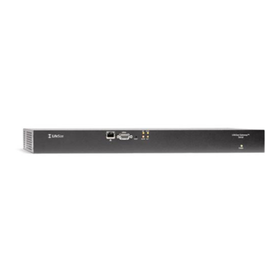
Physical Description HYSICAL This section provides a physical description of the LifeSize Gateway units. ESCRIPTION Figure 2-1 shows the front panel of the LifeSize Gateway unit. Table 2-1 RONT ANEL describes the components of the front panel. Figure 2-1 LifeSize Gateway Front Panel... -
Page 29: Gateway-Pri Rear Panel
Physical Description -PRI R Figure 2-2 shows the rear panel components of the Gateway-PRI unit. Table 2-2 ATEWAY ANEL describes these components. Figure 2-2 Gateway-PRI: Rear Panel Table 2-2 Gateway-PRI Rear Panel Components Component Description ACT LEDs Lights green to indicate that there are active calls in the LifeSize Gateway on the specified PRI line. -
Page 30: Gateway-Serial Rtm
LifeSize Gateway unit an IP address Dedicated IP address for the LifeSize Gateway unit IP address of the router that the LifeSize Gateway unit will use to communicate across the network For an H.323 environment, IP address of the H.323 gatekeeper with... -
Page 31: Verifying The Package Contents
LifeSize Gateway CD-ROM containing product documentation, utilities and online help files. OUNTING THE You can optionally mount the LifeSize Gateway unit in a standard 19-inch rack. Two mounting brackets and a set of screws are included in the LifeSize ATEWAY Gateway unit shipping box. -
Page 32: Lifesize Gateway Unit Initial Configuration
Fitting a Bracket for Rack Mounting Pass the screws through the brackets and tighten them into the screw holes on each side of the LifeSize Gateway unit using a suitable screwdriver. Insert the LifeSize Gateway unit into the 19-inch rack. -
Page 33: Connecting To Apc
DDRESS IP address and other address information. The serial port on the LifeSize Gateway unit front panel is used to assign a new IP address to your LifeSize Gateway unit. You must assign the IP address before you connect the LifeSize Gateway unit to the network. - Page 34 Set the communication settings in the terminal emulation application on the PC as follows: Baud rate: 9600 Data bits: 8 Parity: None Stop bits: 1 Flow control: None Turn on the power to the LifeSize Gateway unit. LifeSize Gateway User Guide...
- Page 35 A log of the auto-boot events and a VxWorks banner scrolls across the computer monitor. When the LifeSize Gateway unit is started for the first time, two Note VxWorks banners appear. The configuration option appears after the second banner.
-
Page 36: Changing The Configuration Tool Login Password
ASSWORD Procedure Start a terminal emulator session for the LifeSize Gateway unit. Press the RST button on the front panel of the LifeSize Gateway unit. After 60 seconds, a new terminal emulator session begins on the computer monitor. LifeSize Gateway User Guide... -
Page 37: Connecting The Lifesize Gateway Unit To The Lan
LifeSize Gateway interface and press Enter. There is no default password. The configuration menu re-appears. Enter Q and press Enter to exit. ONNECTING THE This section describes how to connect the LifeSize Gateway unit to the Local Area Network (LAN). ATEWAY NIT TO THE Procedure... -
Page 38: Connecting Serial Lines To The Gateway
41 Signaling Interface Pin Layout on page 42 This section describes the following DTE cables supplied with the HYSICAL ESCRIPTION OF Gateway-Serial unit: ABLES V.35/RS366-DTE on page 31 EIA449/RS366-DTE on page 32 EIA530/RS366-DTE on page 33 LifeSize Gateway User Guide... - Page 39 The DB-25 connector provides the RS-366 signaling interface for all Gateway-Serial unit cables. V.35/RS366-DTE Figure 2-5 shows the V.35/RS366-DTE cable. Figure 2-5 V.35/RS366-DTE Cable J2 Male (M-34 Winchester) J1 Male (DB-60) V.35 data J3 Male (DB-25) RS-366 signaling Setting Up Your LifeSize Gateway...
- Page 40 Serial Gateway Cable Connections and Pin-outs EIA449/RS366-DTE Figure 2-6 shows the EIA449/RS366-DTE cable. Figure 2-6 EIA449/RS366-DTE Cable J2 Male (DB-37) J1 Male (DB-60) EIA-449 data J3 Male (DB-25) RS-366 signaling LifeSize Gateway User Guide...
- Page 41 Serial Gateway Cable Connections and Pin-outs EIA530/RS366-DTE Figure 2-7 shows the EIA530/RS366-DTE cable. Figure 2-7 EIA530/RS366-DTE Cable J2 Male (DB-25) J1 Male (DB-60) EIA-530 data J3 Male (DB-25) RS-366 signaling Setting Up Your LifeSize Gateway...
- Page 42 Serial Gateway Cable Connections and Pin-outs EIA530/RS366-DTE- Figure 2-8 shows the EIA530/RS366-DTE-LOS cable. Figure 2-8 EIA530/RS366-DTE-LOS Cable J2 Male (DB-25) J1 Male (DB-60) EIA-530 data J3 Male (DB-25) RS-366 signaling LifeSize Gateway User Guide...
- Page 43 Serial Gateway Cable Connections and Pin-outs KIV7/RS366-DTE Figure 2-9 shows the KIV7/RS366-DTE cable. Figure 2-9 KIV7/RS366-DTE Cable J2 Male (DB-37) J1 Male (DB-60) KIV-7 data J3 Male (DB-25) RS-366 signaling Setting Up Your LifeSize Gateway...
-
Page 44: Data Interface Cable Pin-Out Configurations
Clear To Send CTS A Data Set Ready DSR A Data Terminal DTR A ready Carrier Detect DCD A Terminal Timing TT A Signal Ground — Transmit Data TXD B Transmit Timing TXC B Receive Data RXD B LifeSize Gateway User Guide... - Page 45 Local Loopback — — L, K Remote — — Loopback Loss of Sync — — — — unbalanced Loss of Sync LOS A — — — — Loss of Sync LOS B — — — — Setting Up Your LifeSize Gateway...
-
Page 46: Data Interface Pin Layouts
Serial Gateway Cable Connections and Pin-outs This section illustrates the pin layouts for the Gateway-Serial cable connectors. NTERFACE AYOUTS M-34 C Figure 2-10 shows the M-34 pin assignment. ONNECTOR Figure 2-10 M-34 Pin Layout LifeSize Gateway User Guide... - Page 47 Serial Gateway Cable Connections and Pin-outs DB-37 C Figure 2-11 shows the DB-37 pin layout. ONNECTOR Figure 2-11 DB-37 Pin Layout Setting Up Your LifeSize Gateway...
-
Page 48: Connector
Serial Gateway Cable Connections and Pin-outs DB-25 C Figure 2-12 shows the DB-25 pin layout. ONNECTOR Figure 2-12 DB-25 Pin Layout LifeSize Gateway User Guide... -
Page 49: Signaling Interface Cable Pin-Out Configuration
Call Request Present Next Digit Power Indication Signal Ground — Distant Station Connection Digit Signal Circuit 1 Digit Signal Circuit 2 Digit Signal Circuit 4 Digit Signal Circuit 8 Receive Common Send Common Data Link Occupied Setting Up Your LifeSize Gateway... -
Page 50: Signaling Interface Pin Layout
Serial Gateway Cable Connections and Pin-outs This section illustrates the pin layout for the Gateway-Serial signaling cable IGNALING NTERFACE AYOUT connector. DB-25 C Figure 2-13 shows the DB-25 pin layout. ONNECTOR Figure 2-13 DB-25 Pin Layout LifeSize Gateway User Guide... -
Page 51: Managing And Monitoring The Lifesize Gateway Unit
PC. Using a terminal emulation application running on the PC, you can assign an IP address and subnet mask to the LifeSize Gateway unit. The RJ-45 serial port is used to connect a PC terminal to the LifeSize Gateway unit. -
Page 52: Accessing The Lifesize Gateway Administrator Interface
You can use your web browser from any remote PC station to monitor and to configure the LifeSize Gateway unit. A web server is installed in the LifeSize Gateway unit to facilitate the use of the remote web-based monitoring and management. -
Page 53: Registering The Online Help
If you try to sign in as an Administrator and another Administrator is Note currently signed in, the LifeSize Gateway signs you in as a Read only user and the words Read Only appear at the top of the window. Read only users cannot edit any of the LifeSize Gateway settings. -
Page 54: Netscape Navigator Users
Click Upload in the LifeSize Gateway Administrator tool bar, followed by Refresh. On the toolbar, click Upload. You may need to log out and log back in to the LifeSize Gateway Administrator for the change to take effect. On the toolbar, click Upload. -
Page 55: Configuring The Lifesize Gateway
ONFIGURING THE ATEWAY This section describes what you can configure and how to configure LifeSize Gateways, and includes the following topics: About Gateway Interface Users Viewing LED Information Viewing General Information About the Gateway Viewing Address Settings Changing the Administrator Interface Web Server Port... -
Page 56: About Gateway Interface Users
SERS Gateway and monitor LifeSize Gateway activity. You can view and manage the list of LifeSize Gateway users in the Users tab of the Device section of the LifeSize Gateway interface. The Users tab displays all currently configured users and their access levels. -
Page 57: Editing Gateway Interface Users
Viewing LED Information In the Users tab of the Device section of the LifeSize Gateway interface, you DITING ATEWAY NTERFACE SERS can edit LifeSize Gateway interface users. Procedure In the LifeSize Gateway interface, on the sidebar, click Device. Click the Users tab. -
Page 58: Viewing General Information About The Gateway
Monitoring tab to view a description of that LED. IEWING ENERAL In the Basics tab in the Device interface, you can view and configure general information about the hardware and software the LifeSize Gateway uses. NFORMATION BOUT THE ATEWAY Procedure In the LifeSize Gateway interface, on the sidebar, click Device. -
Page 59: Updating Your License
52 Setting the Gateway Location on page 53 Resetting Default Device Basic Settings on page 53 You use the Basics tab to update your LifeSize Gateway license. PDATING ICENSE Procedure On the sidebar, click Device. Click the Basics tab. -
Page 60: Setting The Time And Date On The Gateway
Viewing General Information About the Gateway You use the Basics tab to choose how your LifeSize Gateway tracks the date and ETTING THE IME AND ATE ON THE time. ATEWAY Procedure On the sidebar, click Device. Click the Basics tab. -
Page 61: Setting The Gateway Location
Viewing General Information About the Gateway You can install the LifeSize Gateway anywhere on your network including at a ETTING THE ATEWAY OCATION remote site. In the Basics tab, you can describe the current location of the LifeSize Gateway. Procedure On the sidebar, click Device. -
Page 62: Viewing Address Settings
Viewing Address Settings IEWING DDRESS In the Addressing tab, you can view address information for the LifeSize Gateway such as IP address informations, Domain Name Server (DNS) ETTINGS information and Ethernet port speed and duplex. Table 3-2 describes the elements that appear on the Addressing tab. -
Page 63: Changing Address Settings
Port 80 is the default Administrator interface web server port. For additional security, you can modify the web server port in the Web tab. DMINISTRATOR NTERFACE ERVER Procedure In the LifeSize Gateway interface, on the sidebar, click Device. Click the Web tab. Configuring the LifeSize Gateway... -
Page 64: Configuring Security
In the Web server port field, enter the port number. On the toolbar, click Upload. ONFIGURING You can configure the access that external programs have to the LifeSize Gateway. These external programs include Telnet, Simple Network ECURITY Management Protocol (SNMP), File Transfer Protocol (FTP), and ICMP (Internet Control Message Protocol, or ping). -
Page 65: About The Gateway Administrator Interface
LifeSize Gateway Administrator interface. Note There may be slight variations between the configuration options described in this section and the options appearing in the LifeSize Gateway you are working with. Table 3-3 Gateway Administrator Interface Tabs... - Page 66 About the Gateway Administrator Interface Figure 3-1 Table 3-4 display and list the elements in the LifeSize Gateway Administrator interface. Figure 3-1 Gateway Administrator Interface LifeSize Gateway User Guide...
- Page 67 Note the Administrator web page of the LifeSize Gatekeeper with which the LifeSize Gateway registers. Enter the IP address of the LifeSize Gatekeeper with which the LifeSize Gateway registers in the Specify Gatekeeper address field in the IP Connectivity section of the Settings tab when the IP connectivity mode option is set to Using gatekeeper.
-
Page 68: Viewing The Status Tab
Viewing the Status Tab IEWING THE The Status tab displays the current rate of use of LifeSize Gateway resources, the total number of current calls, and servicing details. Table 3-5 lists the TATUS information in the Status tab. Table 3-5... -
Page 69: Viewingb Channel Status
This section applies only to Gateway-PRI. IEWING HANNEL Note TATUS From the Status tab in the LifeSize Gateway interface, you can view detailed status information for each B channel. Procedure In the LifeSize Gateway interface, on the sidebar, click Gateway (if not already selected). -
Page 70: Configuring Gateway Settings
90 About DTMF Settings on page 96 Configuring Advanced Commands on page 100 In the Basics section of the Settings tab, you can set the LifeSize Gateway ONFIGURING ASIC ATEWAY ETTINGS identifier, which is the name that the LifeSize Gateway uses when registering to a gatekeeper and when dialing to endpoints. -
Page 71: Configuring Ip Connectivity Settings
LifeSize Gateway operates, set the address of ETTINGS the gatekeeper with which the LifeSize Gateway registers, and define the way in which the LifeSize Gateway interacts with the gatekeeper. You can configure the IP connectivity mode in the following two ways: Using a gatekeeper—The LifeSize Gateway registers with a... - Page 72 Select the Registration refresh every n seconds check box to set the Time To Live interval (in seconds) that determines how often the LifeSize Gateway sends a “keep alive” message to the gatekeeper to ensure that the LifeSize Gateway registration is listed with the gatekeeper and does not expire.
- Page 73 13 step Gatekeepers can perform load balancing on the network using feedback from the LifeSize Gateway in the form of Resource Available Indication (RAI) messages that inform the gatekeeper of LifeSize Gateway resource availability. If the LifeSize Gateway is unavailable, the gatekeeper performs line hunting operations to route the call to an alternative gateway.
- Page 74 Always start from last successful peer—The LifeSize Gateway attempts to connect a call to the last peer device in the Peer list section with which a call was successfully established. An arrow in the Peer list section indicates with which of the peer devices a call was last connected successfully.
- Page 75 LifeSize Gateway fails to establish a Transmission Control Protocol (TCP) connection to the specified peer device after a timeout; the LifeSize Gateway receives a “Release Complete” message from a peer device with a “No Resources” call rejection reason, or one of the other reasons that the Peer-to-Peer disconnect reason add advanced command specifies;...
- Page 76 The peer hunting process stops when one of the peer devices accepts Note the call or when the call is rejected with a disconnect reason. When a LifeSize Gateway has scanned the Peer list section and still cannot connect a call, the...
- Page 77 LifeSize Gateway allows incoming calls from IP-side entities not defined in the Peer list section. (Gateway-PRI only) In the Reject calls from peer devices when less than n B channels are free field, type the lower capacity threshold for rejecting calls from H.323 peer devices.
-
Page 78: Configuring Ivr Settings
Indicates that the purpose of the message is to transport higher-layer information. In the IVR section of the Settings tab, you can configure the LifeSize Gateway ONFIGURING ETTINGS to route calls using an Interactive Voice Response (IVR) system. - Page 79 Configuring Gateway Settings Use internal IVR—Enables the LifeSize Gateway IVR functionality so that incoming calls can route to an endpoint on the IP network. Follow step 5 step Note The IVR must be enabled for the port that supports IVR.
-
Page 80: Configuring Outgoing Call Delimiters
The G.722 and G.722.1 formats, using a digital sampling rate of 7 KHz, provide higher quality voice sampling with a greater dynamic range. The LifeSize Gateway does not transcode G.722 or G.722.1, but supports them transparently. Since the G.722 codec is of a much higher audio quality than other codecs and requires higher bandwidths, the LifeSize Gateway supports G.722... - Page 81 G.723.1 (IP) to G.711 (ISDN) G.728 (ISDN) to G.711 (IP) G.711 (IP) to G.728 (ISDN) When your unit includes both a LifeSize Gateway and LifeSize Multipoint, Note G.728 transcoding is supported on the Multipoint only. Each audio codec differs in the audio quality, compression, and bit rates that it provides.
- Page 82 MLP, HMLP and VarMLP formats. If transcoding or T.120 capabilities are required, the LifeSize Gateway has to reserve resources for these. The LifeSize Gateway can differentiate between those calls that support T.120 and those that do not. When receiving calls, the LifeSize Gateway can check whether you are reserving resources for transcoding or for T.120 capabilities.
-
Page 83: Configuring Encoding/Decoding Protocols
In the Transcoding priority field, choose the priority that determines the order of requested audio transcoding or choose Disable to disable audio transcoding priority. When your unit includes both a LifeSize Gateway and LifeSize Note Multipoint, G.728 transcoding is supported on the Multipoint only. -
Page 84: Configuring Isdn Channel Bonding Settings For Downspeeding
Gateway attempts to connect a video call at the specified lower bit rate. When downspeeding is complete and the call is connected at the specified lower bit rate, the LifeSize Gateway notifies the Internet Protocol (IP) endpoint of the new call rate. -
Page 85: Configuring Quality Of Service Settings
Call disconnects (default) WAN (ISDN) to LAN (IP) disabled Call disconnects. You can configure the LifeSize Gateway to add a Quality of Service (QoS) IP ONFIGURING UALITY ERVICE ETTINGS precedence code in the IP header of outbound packets on the IP network. - Page 86 Bits 6-7: reserved for future use The possible Precedence settings are as follows: 111 = Network Control 110 = Internetwork Control 101 = CRITIC/ECP 100 = Flash Override 011 = Flash 010 = Immediate 001 = Priority 000 = Routine LifeSize Gateway User Guide...
- Page 87 In the Quality of Service section of the Settings tab, you can assign a priority level to video and voice calls. Procedure In the LifeSize Gateway interface, on the sidebar, click Gateway (if not already selected). Click the Settings tab.
-
Page 88: Configuring Alert Indications
In the Alert Indications section of the Settings tab, you can select which events ONFIGURING LERT NDICATIONS trigger Simple Network Management Protocol (SNMP) traps. You can also define multiple SNMP servers to which the LifeSize Gateway sends the SNMP traps. Note The LifeSize Gateway supports traps in the SNMPv1 format. Procedure In the LifeSize Gateway interface, on the sidebar, click Gateway (if not already selected). - Page 89 Upload button. Related Topics Gateway Event Types on page 81 Trap Severity Enumeration on page 87 Table 3-8 lists proprietary LifeSize SNMP trap event types for the ATEWAY VENT YPES Gateway-PRI, as detailed in the RvTrapEventType xtual convention. Table 3-9...
- Page 90 T.120 resources. Network problem A problem occurs on the network. TRUE Major FALSE Clear Card extract/Hot A card has been removed from the LifeSize TRUE Critical Swap chassis under power or inserted into the FALSE Clear chassis under power, or the when the LifeSize Gateway enters maintenance mode.
- Page 91 T.120 resources. Network problem A problem occurs on the network. TRUE Major FALSE Clear Card extract/Hot A card has been removed from the LifeSize TRUE Critical Swap chassis under power or inserted into the FALSE Clear chassis under power, or the when the LifeSize Gateway enters maintenance mode.
- Page 92 A call to a peer has failed because the peer Major - peer list empty list is empty. Incompatible sw An attempt to burn a version of the LifeSize Warning version install Gateway software onto incompatible hardware occurs. Call from...
- Page 93 T.120 resources. Network problem A problem occurs on the network. TRUE Major FALSE Clear Card extract/Hot A card has been removed from the LifeSize TRUE Critical Swap chassis under power or inserted into the FALSE Clear chassis under power, or the when the LifeSize Gateway enters maintenance mode.
- Page 94 A call to a peer has failed because the peer Major - peer list empty list is empty. Incompatible sw An attempt to burn a version of the LifeSize Warning version install Gateway software onto incompatible hardware occurs. Call from...
-
Page 95: Configuring Gateway Resources For Calls
ATEWAY ESOURCES ALLS In the Resources section of the Settings tab, you can reserve LifeSize Gateway resources for T.120 enabled calls and for audio transcoded video calls. This section also displays the total number of calls that the LifeSize Gateway supports at specified bandwidths. - Page 96 The LifeSize Gateway supports up to 30 video calls on two B channels. If transcoding or T.120 capabilities are required, the LifeSize Gateway has to reserve resources for these.
-
Page 97: Configuring Gateway Encryption
If not, it connects without encryption. Encryption required—Only connects encrypted calls. Encryption can either be AES 128 or DES 56. The LifeSize Gateway does not allow non-encrypted calls to connect. Strong encryption required—Only allows AES 128 encrypted calls. -
Page 98: Configuring Advanced Settings
Note call must have the same encryption levels. If the same encryption on all channels is not achieved, the call disconnects. In the Security section of the Settings tab, you can configure LifeSize Gateway encryption settings. Procedure In the LifeSize Gateway interface, on the sidebar, click Gateway (if not already selected). - Page 99 Services tab to process the call. If the service bit rate is set to Auto, the LifeSize Gateway process the call at the bearer rate.
- Page 100 Choose the default bit rate. When using a service with the bit rate of n kbps for rate set to Auto, the LifeSize Gateway uses the default bit services defined to use rate if the received bearer rate is not one of the supported bit ‘auto’...
- Page 101 Advanced Settings—ISDN (or Serial) to IP Calls Field or Check Box Description Conceal caller ID Select to have the LifeSize Gateway hide the identifier of (unavailable in the calling endpoint on the ISDN network, regardless of Gateway-Serial) whether or not the Support Presentation Restriction advanced setting is selected.
- Page 102 Description Support H.323 Fast The H.323 fast start functionality enables endpoints that Start in voice-only call support the feature to join a voice conference in the LifeSize setup (unavailable in Gateway more quickly. Gateway-Serial) Standard call setup requires four round trips of messages between endpoints before the first media stream is exchanged between peers.
- Page 103 Advanced Settings—ISDN Options Field or Check Box Description Request ISDN rollover Select to define when the LifeSize Gateway uses the ISDN when less than n B rollover feature (which is defined in advanced commands— channels are available Configuring Advanced Commands...
-
Page 104: About Dtmf Settings
Advanced Settings—General Field or Check Box Description Restrict Gateway use to Select for the LifeSize Gateway to send and receive calls to MCU conferences only and from an MCU only. This setting, together with a scheduling server, reserves resources for scheduled conferences only. - Page 105 The local telephone company receives each pair of tones, decodes the number dialed and makes the connection. Table 3-17 DTMF Tone Assignments 1209 Hz 1336 Hz 1477 Hz 1633 Hz 697 Hz 770 Hz 852 Hz oper 941 Hz Configuring the LifeSize Gateway...
- Page 106 Configuring Gateway Settings DTMF The LifeSize Gateway passes incoming in-band DTMF signals to the ISDN or BOUT ETECTION ON serial-side endpoint unchanged. In addition, you can configure the LifeSize -ISDN ERIAL Gateway to convert H.245 out-of-band DTMF signals from the IP side to ALLS in-band signals on the ISDN or serial side.
-
Page 107: Configuring Dtmf Settings
Gateway (if not already selected). Click the Settings tab. Click the Advanced button. In the IP to ISDN Calls section of the Gateway-PRI, you can select the Translate DTMF from IP out-of-band (H.245) to ISDN in-band (G.711 only) check box. -
Page 108: Configuring Advanced Commands
Configuring Gateway Settings In the ISDN to IP Calls section of the Gateway-PRI, you can select the Duplicate DTMF signal from ISDN side as out-of-band on IP side check box. In the Serial to IP Calls section of the Gateway-Serial, you can select the Duplicate DTMF signal from Serial side as out-of-band on IP side check box. - Page 109 Configuring Gateway Settings Table 3-18 Advanced Command Settings Command Description AddService2SrcNum Notifies the IP endpoint of the LifeSize Gateway service number to which the ISDN-side endpoint has called. Parameters: disable/enable. CallSignalPort Notifies the gatekeeper to which the LifeSize Gateway is registered on which port to communicate.
- Page 110 H.323 call disconnect reason, as listed in Table 3-6. Procedure In the LifeSize Gateway interface, on the sidebar, click Gateway (if not already selected). Click the Settings tab. Click the Advanced button. Click Commands. The Advanced Commands dialog box appears.
-
Page 111: About Gateway Services
The LifeSize Gateway has two types of services: default and user-defined. Default services come pre-configured on the LifeSize Gateway. User-defined services are services that you can define at any time using the LifeSize Gateway interface. Upon registration with a gatekeeper, the LifeSize Gateway provides the gatekeeper with a list of LifeSize Gateway services. -
Page 112: Viewing Existing Services
Adding or Editing Services on page 104 Deleting Gateway Services on page 106 The Services tab in the LifeSize Gateway interface displays a list of currently IEWING XISTING ERVICES defined services for the LifeSize Gateway in a table format with the following columns and fields: Prefix—Displays the prefix that identifies the service. - Page 113 The Auto setting is for video calls only. If the IP network endpoint has a configured bit rate that is not one of the options listed in this field, the LifeSize Gateway uses the default bit rate configured in the Default Service Bit Rate field in the Advanced section of the Settings tab.
-
Page 114: Deleting Gateway Services
Click the Services tab. Select a service and click Delete. ONFIGURING In the PRI Port or Serial Port tabs, you can configure physical line settings for LifeSize Gateway ports. The following topics discuss the settings you can ETTINGS configure. Configuring Basic Port Settings... -
Page 115: Configuring Basic Port Settings
Select the Port enabled check box to enable this port. For Gateway-PRIs and Gateway-Serials, if this setting is deselected, the CD LED light on the rear panel of the LifeSize Gateway is disabled. (Gateway-PRIs only) In the Port phone numbers section, choose one of the following option buttons: Single Number—Defines a single number for this... -
Page 116: Configuring Port Physical Interface Settings
Configuring Port Settings (Gateway-PRIs only—optional) Select the Strip Local Area Code check box if you want the LifeSize Gateway to strip local area codes for outbound calls to the ISDN network. Note The type of line connected to this PRI port appears in the Physical standard field. - Page 117 Configuring Port Settings In the Network access field, choose the LifeSize Gateway national access type: TE (Terminal Equipment) or NT (Network Terminator) device. In the Clock source field, choose the LifeSize Gateway clock source: Master (the LifeSize Gateway provides the clock signal)
- Page 118 IGNALING properties of the specified PRI port. Procedure In the LifeSize Gateway interface, on the sidebar, click Gateway (if not already selected). Click the applicable PRI Port tab. Click the Physical Interface button.
-
Page 119: Serial Ports
When a cable is connected to a serial port, the LifeSize Gateway identifies the type of the cable and displays the information in the Interface and Physical standard fields of the Physical Interface section. - Page 120 Manual Control—Enables an Administrator to manually connect a call via the LifeSize Gateway web user interface. Different signaling protocols are available depending on the...
- Page 121 OOPBACK loopback control options. ONTROL PTIONS Procedure In the LifeSize Gateway interface, on the sidebar, click Gateway (if not already selected). Click the applicable Port tab. Click the Physical Interface button. Click the Advanced button to configure non-standard signal state and loopback control options: Force Signal State—Enables separate control over...
- Page 122 IEWING ONNECTION TATUS loopback control settings. Procedure In the LifeSize Gateway interface, on the sidebar, click Gateway (if not already selected). Click the applicable Port tab. Click the Connection Status button. When DTE is selected in the Interface field, the...
- Page 123 When DCE is selected in the Interface field, the Connection Status screen displays the signal state and loopback control settings defined by the standard logic of the LifeSize Gateway. Blue lines indicate that the specified signal is on. Gray lines indicate Note that the specified signal is off.
-
Page 124: About Advanced Isdn Settings For Pri Gateways
Configuring Port Settings Table 3-20 Connection Status and Loopback Control Signal Descriptions Signal Description Data Line Occupied This section applies only to Gateway-PRI. BOUT DVANCED Note ISDN S ETTINGS FOR PRI G ATEWAYS In the Advanced ISDN section of the PRI Port tabs, you can view and configure ISDN settings for Gateway-PRI. - Page 125 ISDN settings from that port. When you select this option, you cannot make any edits to the configuration settings. This option is unavailable in LifeSize Gateway that support only one PRI port. NSF S The NSF Information Element (IE) feature enables system administrators to...
- Page 126 Octet fields. Table 3-22 Octet Field Functions Octet Function Octet 3 Octet 3 represents the total number of Octet 3.X fields required for the specific information element, including the Octet 3 field itself. LifeSize Gateway User Guide...
- Page 127 For a TON setting of Network, the standard integer value is 3 and the standard binary value is 0011. For a TON setting of Local, the standard integer value is 4 and the standard binary value is 0100. Configuring the LifeSize Gateway...
- Page 128 The octet contains eight bits numbered from 1 to 8 and from right to left, so that Bit 1 is rightmost and Bit 8 is leftmost. The bits contain values representing the following functions: Bits 1-7 represents the parameterized field coding value. Bit 8 is for future use. LifeSize Gateway User Guide...
- Page 129 Pre-subscribed Common Carrier Operator Reserved Call-Associated Temporary Signaling Connection (TSC) Notification of Call-Associated TSC clearing Reserved Reserved Reserved Table 3-24 Service Binary Facility Coding Values Bits Feature Software Defined Network (SDN). Includes Global SDN) AT&T Megacom Configuring the LifeSize Gateway...
- Page 130 Wide Area Telecommunications Service (WATS) AT&T Accunet Switched Data Video Gateway (SDVG) Long Distance Service International 800 (1800) Reserved Reserved Reserved Reserved Multiquest Reserved Test call Inward Wide Area Telecommunications Service (INWATS) SDN-K (Key Service Protection) Call Redirection Service LifeSize Gateway User Guide...
- Page 131 ISDN I NFORMATION LEMENTS Procedure In the LifeSize Gateway interface, on the sidebar, click Gateway (if not already selected). Click the applicable PRI Port tab. Click the Advanced ISDN button. Click Add to add a new ISDN information element or select an existing one and click Edit to modify it.
- Page 132 Default Local None, Append Local Area Code Default Any except Local None Any except Default None, Strip Prefix You are now ready to configure your required Network Specific Facility settings (see Configuring Network Specific Facility Settings). LifeSize Gateway User Guide...
- Page 133 IE 2 Octets AT&T Accunet AT&T Megacom AT&T Megacom 800 AT&T SDDN AT&T Accunet + SDVG AT&T Megacom + SDVG AT&T Megacom 800 + SDVG AT&T SDDN + SDVG MCI VNET Sprint VPN —or— Choose Custom. Configuring the LifeSize Gateway...
- Page 134 5, Bits 7-1. When you select Custom in the Type field, the values entered in the Octet 4 or Octet 5 fields are not subject to bit restriction. Repeat step 1 for as many additional NSF information elements as necessary. LifeSize Gateway User Guide...
-
Page 135: Configuring Port Call Policies
In the Call Policies section of the PRI Port or Serial Port tabs, you can ONFIGURING OLICIES configure the incoming call routing methods available in the LifeSize Gateway for each specified port. You can define each port with different settings. Procedure In the LifeSize Gateway interface, on the sidebar, click Gateway (if not already selected). -
Page 136: Configuring Port Supported Services
7, otherwise skip to step (Gateway-PRI only) In the Incoming number of digits field, enter the number of digits you want the LifeSize Gateway to expect during overlap receiving. The LifeSize Gateway waits until this number of specified digits is received and then processes the whole number. -
Page 137: Viewing Call Information
To enable or disable a service for this port, select it and click Enable or Disable. IEWING The Calls tab displays a list of the calls currently defined in the LifeSize Gateway and the basic details of each call. The Calls tab displays the following NFORMATION information in table format: Call ID—Displays the call identifier. -
Page 138: Refreshing Call Information
130 Viewing Call Details on page 130 Disconnecting Calls on page 133 You can configure the LifeSize Gateway interface to refresh information that EFRESHING NFORMATION appears in the Calls tab every ten seconds. Procedure In the LifeSize Gateway interface, on the sidebar, click Gateway (if not already selected). - Page 139 Displays the video transcoding protocol, the frame format, and the bandwidth of the video calls in both directions between the source endpoint and the LifeSize Gateway. Note The Video 2 stream is active when dual video streams for a single call are in use.
- Page 140 Packet Loss (%) Displays the rate of packet loss in communication from the IP side of the call to the LifeSize Gateway, regardless of whether the source endpoint is located on an ISDN (or serial) or IP network. Encryption Indicates the encryption algorithm in use for the call (if any).
-
Page 141: Disconnecting Calls
In the Calls tab, you can disconnect a currently active call or disconnect all ISCONNECTING ALLS active calls. Procedure In the LifeSize Gateway interface, on the sidebar, click Gateway (if not already selected). In the Calls tab, select a call and click Disconnect, or to disconnect all calls, click Disconnect All Calls. IEWING ATEWAY In the Event Log tab, you can view a list of reported alarm events. -
Page 142: Configuring Gateway Maintenance Tasks
ATEWAY upgrading software. In maintenance mode, the LifeSize Gateway cannot accept AINTENANCE new calls. You can disconnect all calls currently active in the LifeSize Gateway, ASKS or wait for them to disconnect. In maintenance mode, you can only modify the... - Page 143 Upload on the toolbar to save these settings to configuration memory prior to saving the configuration file. Procedure In the LifeSize Gateway interface, on the sidebar, click Device. Make sure that the settings in the Basics, Addressing, Web and Users tabs are correct.
-
Page 144: Importing Configuration Files
Importing Configuration Files MPORTING You can import the settings of a saved LifeSize Gateway unit configuration file from a storage device on your network. You can use the saved configuration file ONFIGURATION to restore the settings to the current LifeSize Gateway unit or to configure ILES another LifeSize Gateway unit. - Page 145 Importing Configuration Files Click Upload to save the settings in configuration memory. Note Uploading the file resets the device. Configuring the LifeSize Gateway...
- Page 146 Importing Configuration Files LifeSize Gateway User Guide...
-
Page 147: Using The Lifesize Gateway
(*), pound sign (#) or delimiter. The service prefix indicates that the call is to go through the LifeSize Gateway, and also indicates the properties of the call such as the call type or bandwidth requirements. -
Page 148: About Gateway Service Prefixes
B channel phone numbers. Because some H.323 endpoints do not support dialing long number strings or two phone numbers, you can use a delimiter to indicate to the LifeSize Gateway the end of one number and the beginning of the other. See... - Page 149 1816455318—The destination phone number including the area code. *—The second number delimiter. The second number delimiter tells the LifeSize Gateway to dial the destination phone number a second time. Dialing Example 4: 2B video calls The number string 821816455318*1816455319 is a 2B video call from an IP network terminal to an H.323 endpoint on another IP network or to a terminal on...
-
Page 150: About Dialing In To The Ip Network Via The Gateway
If a routing method fails, the LifeSize Gateway automatically tries to route the call through the next routing method in line. If all methods fail, the call is rejected. The call might also be rejected if the LifeSize Gateway routes the call to an endpoint that is busy or not available. - Page 151 Table 4-1 Routing Methods Routing Method Explanation The LifeSize Gateway supports two forms of DID (Direct Inward Dialing): Multiple Subscriber Network (MSN) and sub-addressing. MSN—The telephone company assigns a group of phone numbers to a particular ISDN line by the telephone company.
- Page 152 LifeSize gatekeeper or a third-party gatekeeper. The LifeSize Gateway internal IVR can handle up to 30 simultaneous incoming calls. With the LifeSize Gateway, you can define an endpoint on the IP network as an IVR operator (see Configuring IVR Settings page 70 for more information).
-
Page 153: About The Ivr Operator
5776—The extension number of the requested endpoint. TCS4 only routes H.320 video calls. Note When the LifeSize Gateway does not support DID or TCS4, you can reach an BOUT IALING THROUGH endpoint using the Interactive Voice Response (IVR) routing mechanism. - Page 154 When IVR is enabled, you are answered by a recorded message prompting you to enter the destination endpoint phone number. If you do not know the destination endpoint number, the IVR routes the call from the LifeSize Gateway using ISDN to the IP network endpoint that is defined as the IVR operator.
-
Page 155: Troubleshooting The Lifesize Gateway
ROUBLESHOOTING THE ATEWAY This section covers problems you might encounter when configuring, operating and managing the LifeSize Gateway. This chapter provides suggested actions you can use to solve the problems, and includes the following topics. This chapter discusses the following topics:... - Page 156 Flow control: None Make sure that the terminal cable that is shipped with the unit or a null cable is securely connected to the LifeSize Gateway serial port and to the computer serial port. Verify that the LifeSize Gateway can communicate with the terminal by using the procedure below.
-
Page 157: About Led Indications
Symptom The 10/100BaseT link LED is embedded in the 10/100BaseT jack on your left as you face the LifeSize Gateway front panel. When this LED is lit, it indicates that the LifeSize Gateway is connected to the network. Recommended Action Make sure that the LAN cable is connected to the 10/100BaseT-1 jack on the front panel of the LifeSize Gateway. - Page 158 Errors that trigger the alarm include loss of signal, loss of frame, excessive errors and incorrect configuration. The LifeSize Gateway has an ALRM LED on the front panel and an alarm for each port on the rear panel. The ALRM LED on the front panel indicates that there is a line error.
-
Page 159: About Problems With Outbound Calls
Make sure that the LifeSize Gateway port configuration is compatible with how the ISDN or serial line is configured. If the LifeSize Gateway is connected to a PBX, make sure that the PBX is properly connected and configured. If the LifeSize Gateway is connected directly to a central office switch, make sure that the PSTN line is configured to support the LifeSize Gateway (for Gateway-PRI). -
Page 160: About Problems With Inbound Calls
For PRI or serial (DCE) ports, make sure that the DID number is associated with an endpoint registered with a gatekeeper and that the number is included in the registration profile of the endpoint. Incoming calls the LifeSize Gateway receives for unused PRI phone numbers are disconnected. LifeSize Gateway User Guide... - Page 161 About Problems with Inbound Calls Make sure that the PRI line is in working order. Disconnect the PRI line from the LifeSize Gateway and connect it to a regular PSTN phone. Dial the number. If the phone does not ring, the DID line is out of order.
-
Page 162: Monitoring From A Remote Site
When the volume of the DTMF tones generated by the dialing endpoint is low, the IVR might not recognize one or more of the tones. If the LifeSize Gateway does not find an endpoint with a phone number corresponding to the tones dialed, the IVR treats this string as an incorrect number and disconnects the call. -
Page 163: Using The Hyperterminal Configuration Commands
The LED Monitoring tab appears. SING THE This section describes configuration commands that you can access through the LifeSize Gateway serial port. You can use some of these commands to set YPERTERMINAL device parameters that are unavailable in the Gateway interface. This section... -
Page 164: Changing A Global User Name And Password
LifeSize Gateway. These applications include the Upgrade Utility that allows ASSWORD you to change the LifeSize Gateway software, the Upload Utility that allows you to change the IVR messages, and the Telnet utility that allows you to monitor the LifeSize Gateway operations. This user name and password are also used to log in to the Gateway interface. -
Page 165: Setting Echo Cancellation
Press 0 to disable echo cancellation. Press 1 to enable echo cancellation. Press Enter. You can set the port number that the LifeSize Gateway uses for posting its web ONFIGURING THE ERVER pages. The default value is 80, which is the standard for web server ports. If another port is used in your environment, you can use this command to change the LifeSize Gateway module web server port setting. -
Page 166: Setting T.120 Data Collaboration Capability
At the 0/1-disable/enable echo cancellation (voice calls) prompt, do one of the following: Press 0 to disable T.120. Press 1 to enable T.120. Press Enter. You can restore the factory default settings to the LifeSize Gateway from the ESTORING THE ACTORY EFAULT command line. -
Page 167: Configuring The Ethernet Port
Using the Hyperterminal Configuration Commands You can use the command line commands to configure the speed of the LifeSize ONFIGURING THE THERNET Gateway Ethernet port. Procedure At the prompt for the command line options, press A to display the advanced command menu. - Page 168 Using the Hyperterminal Configuration Commands LifeSize Gateway User Guide...
-
Page 169: Using The Lifesize Audio Message Utility
SING THE UDIO ESSAGE TILITY This section describes the LifeSize Audio Message Utility, and includes the following topics: Introduction About Gateway Call Routing Launching the Utility Playing a Message Recording a Message Replacing a Message Uploading a Message to a Device... -
Page 170: Introduction
Introduction NTRODUCTION The LifeSize Audio Message Utility is an interactive GUI that enables you to record and replace messages and upload new messages to the call routing mechanisms in LifeSize devices. Each LifeSize device has a built-in set of audio messages. The default messages are in English. -
Page 171: Playing A Message
Target Type field. ESSAGE LifeSize Gateway Messages The devices available in the Target Type drop-down list vary according to Note the LifeSize devices included in your installation. The following LifeSize Gateway messages are available: ATEWAY ESSAGES Table 6-1 LifeSize Gateway version 5.0 Messages... -
Page 172: Recording A Message
The options available in the Target Type drop-down list vary Note according to the LifeSize devices included in your installation. The Audio Recordings window displays the messages currently uploaded to the target device. Ensure the message type you wish to play is enabled in the Audio Recordings window. -
Page 173: Replacing A Message
Note The options available in the Target Type drop-down list vary according to the LifeSize devices included in your installation. The Audio Recordings window displays the messages currently uploaded to the target device. Click the message type in the Audio Recordings window you wish to replace. -
Page 174: Uploading A Message To A Device
The Customize SNMP Settings dialog box displays. Enter the required read community and write community values and click OK. Click the Upload Messages button. The Upload in progress window appears, and the message files are uploaded and burned onto the target device. LifeSize Gateway User Guide... -
Page 175: Viewing Message Details
The options available in the Target Type drop-down list vary Note according to the LifeSize devices included in your installation. The names of audio message files currently uploaded to the target device appear in the Recorded Message field of the Audio Recordings window. -
Page 176: Using Express Setup
When you have completed the recording and replacement procedure, the Express Setup dialog box displays the new list of message types and message files associated with each type. Click Upload. The Upload dialog box appears. LifeSize Gateway User Guide... - Page 177 Using Express Setup Type the IP address of the target device. Type the user name and password as defined in the network configuration settings of the LifeSize device. Click the Upload Messages button to complete the upload procedure. The Upload in progress window displays. The message files are uploaded and burned onto the target device.
- Page 178 Using Express Setup LifeSize Gateway User Guide...
-
Page 179: Using The Lifesize Software Upgrade Utility
The upgrade files are uploaded and then burned into the memory of the LifeSize Gateway. - Page 180 Launching the Utility AUNCHING THE This section describes how to install and launch the LifeSize Software Upgrade Utility. TILITY Procedure Download the UpgradeUtility.exe file from the LifeSize Gateway directory on the LifeSize FTP site at ftp://support@ftp.lifesize.com. Contact LifeSize Customer Support if you have not received a login user name and password for accessing the LifeSize FTP site.
- Page 181 Click the Upgrade button to upgrade all components of the LifeSize Gateway software (or only those components you manually selected via the Customize option). The LifeSize Software Upgrade Utility informs you whether or not the upgrade is successful. Note When the upgrade is complete, the LifeSize Gateway automatically resets itself and starts operation with the new software version.
- Page 182 Upgrading Software LifeSize Gateway User Guide...
-
Page 183: Cable Connections And Pin-Outs
ABLE ONNECTIONS AND OUTS This section describes the pin-to-pin and pin-out configurations of the connectors and cables of the LifeSize Gateway unit, including the following topics: Unit RS-232 9-Pin Serial Port RJ-45 8-Pin IP Network Port RJ-45 Serial Port Adapter Cable... -
Page 184: Unit Rs-232 9-Pin Serial Port
Unit RS-232 9-Pin Serial Port RS-232 9-P Table 8-1 describes the LifeSize Gateway unit RS-232 9-pin D-type serial port pin-out configuration. ERIAL Table 8-1 RS-232 9-pin D-Type Serial Port Pin-out Function Input Output LifeSize Gateway User Guide... -
Page 185: 8-Pin Ip Network Port
RJ-45 to DB-9 adapter DAPTER cable used to connect a PC terminal to the RJ-45 serial port. This cable is provided with the LifeSize Gateway unit. ABLE Table 8-3 Pin-to-Pin Configuration of the RJ-45 to DB-9 Adapter Cable... -
Page 186: Isdn Port
ISDN Port ISDN P Table 8-4 describes the ISDN port RJ-45 connector pin-out configuration. Table 8-4 ISDN Port RJ-45 Connector Pin-out Function RXD + RXD - TXD + TXD - LifeSize Gateway User Guide... -
Page 187: Technical Specifications
ECHNICAL PECIFICATIONS This section provides technical specifications for the LifeSize Gateway. ECHNICAL PECIFICATIONS Table 9-1 LifeSize Gateway Unit Technical Specifications ABLE Unit Dimensions Height: 1U (1.75 inches or 44.45 mm) Width: 17.25 inches (438.15 mm) Depth: 10 inches (254 mm) Weight: 4.45 kg (9.81 lbs)—may vary according... - Page 188 Technical Specifications Table Table 9-1 LifeSize Gateway Unit Technical Specifications (continued) Rear panel ACT 1 to 4 (Gateway-Serial) ALRM 1 to 4 Push Buttons RST (front panel) Communication Interfaces Front panel Ethernet 10/100 Mbps auto-negotiate speed select Asynchronous serial port RS-232 connected via...
- Page 189 Technical Specifications Table Table 9-1 LifeSize Gateway Unit Technical Specifications (continued) Memory 32 MB on-board flash memory for field upgrades, supports up to 64 MB 1 MB L-2 Cache at 200 MHz or more 128 MB SDRAM, supports up to 256 MB...
- Page 190 Technical Specifications Table LifeSize Gateway User Guide...
-
Page 191: Index
NDEX A A A A auto dial 92 auto-boot 24 access control 3 B B B B access levels 48 ACT LED 20, 21, 22 bandwidth 88, 104, 112, 129 Add ISDN Information Elements dialog box 116, 119, 123 call overhead 16 resource allocation 17 Add peer dialog box 67 supported 6... - Page 192 146 delete ISDN information elements 127 into IP 142 delete services 106 out from IP 139 detect DTMF 99 through IVR 145 disconnect calls 133 edit interface users 49 dialing examples 140–146 184 LifeSize Gateway User Guide...
- Page 193 DID 3, 93, 127, 143 fractional channels 109 direct dialing 3 Fractional dialog box 109, 110 Discovered Gatekeepers dialog box 64 framing 110 downspeeding 5, 76, 82, 83, 101 front panel 20 DTE 30, 111 FTP 56 DTMF 3, 82, 83, 85, 96, 97 G G G G convert signals 98 detection 98...
- Page 194 O O O O supported 6 supported services 128 operating system 180 SVGA 43 operator access level 48 power supply 181 presentation restriction 91, 93, 96 P P P P call handling capacity 16 package contents 23 186 LifeSize Gateway User Guide...
- Page 195 connecting gateway directly to central office serial port connector 20, 43 switch 13 DB-9 43 connecting gateway to a PBX 13 services 103, 128 interface features 8 default 103 ISDN connections 12 prefix 103, 128, 140 ports 108 user defined 103 PRI LINE connectors 21 Services tab 91, 104 PRI Port tab 116...
- Page 196 171 user-defined services 103 Users tab 48, 49 V V V V V.35 30, 111 Version Details dialog box 51 video conferencing protocols 6 video protocols 6 enable H.263, H.263+,H.264 75 video resolutions 6 188 LifeSize Gateway User Guide...
Need help?
Do you have a question about the Gateway-PRI and is the answer not in the manual?
Questions and answers