
Related Manuals for ETC ArcLamp System


Summary of Contents for ETC ArcLamp System
- Page 1 ArcLamp System Installation Manual Part Number: 7490M2130 Rev: E Released: 2020-12...
- Page 2 To view a list of ETC trademarks and patents, go to etcconnect.com/ip. All other trademarks, both marked and not marked, are the property of their respective owners. ETC intends this document, whether printed or electronic, to be provided in its entirety.
-
Page 3: Table Of Contents
Table of Contents Introduction Document Conventions Help from ETC Technical Services Safety Chapter 1 System Overview Maximum System Limits ArcLamps Overview ArcLamp Driver ArcLamp Driver Wiring Specifications Control Specifications Chapter 2 Prepare for Installation Installation Location ArcLamp Drivers Power Disconnect Device... - Page 4 ArcLamp with ArcMesh Configuration and Commissioning ArcLamp RDM Configuration Maintenance Troubleshooting LED Indicators Overload Protection Fade to Warm Behavior Appendix A Bridge Output Channels Voltage Drop Wall-Mount Bridging Kits Rack-Mount Bridging Kits Output Channel Control Switches Example Bridge Configurations ArcLamp System Installation Manual...
- Page 5 Bridging Procedure Appendix B Emergency Driver Power Input Wiring Wall-Mount Emergency Drivers Wall-Mount Emergency Driver Installation Terminate Normal Sense Input Terminate Maintained (Emergency) Input Rack-Mount Emergency Drivers Rack-Mount Emergency Driver Installation Appendix C Emergency Operation and Test Appendix D TX1 Installation Preparing for Installation Supplies Electrical and Wiring Specifications...
- Page 6 ArcLamp System Installation Manual...
-
Page 7: Introduction
This guide provides step by step instruction on the installation of your ArcLamp system. ArcLamp products are intended for professional use only. Read the entire manual before using this equipment. -
Page 8: Help From Etc Technical Services
Help from ETC Technical Services If you are having difficulties and your problem is not addressed by this document, try the ETC support website at support.etcconnect.com or the main ETC website at etcconnect.com. If none of these resources are sufficient, contact ETC Technical Services directly at one of the offices identified below. -
Page 9: Safety
Safety ArcSystem products are intended for professional use only. Read the entire manual before using this equipment. Note: ArcSystem products contain FCC ID for US: TY0JN5168M6 and Industry Canada (IC) ID: IC 7438A CY05168M6. IMPORTANT SAFEGUARDS When using electrical equipment, basic safety precautions should always be followed including the following: READ AND FOLLOW ALL SAFETY INSTRUCTIONS... -
Page 10: System Overview
Chapter 1 System Overview The ArcLamp System is comprised of ArcLamps and the ArcLamp Driver. This system of products is designed to provide for easy retrofit of an existing space, or simple straight-forward installation for new construction. For renovation installations, ArcLamps simply connect to the ArcLamp Driver using the wires from existing incandescent luminaires, eliminating the need for invasive rewiring. -
Page 11: Maximum System Limits
Maximum System Limits Models are available to meet your installation requirements: ArcLamp 150 Systems Features Standard Wall-Mount ARCLMD150CV24 with ArcMesh Supports 25 total 4.4 W ArcLamps, 6 per ARCLRDMD150CV24 with RDM channel Max. current per channel: 1.5 A Emergency Wall-Mount Max. -
Page 12: Arclamps
E27) and candelabra style (E12 or E14) bases. A Globe Style D E12 or E14 candelabra style base B Candle Style E B15 bayonet style base E26 or E27 standard medium screw F B22 bayonet style base style base ArcLamp System Installation Manual... -
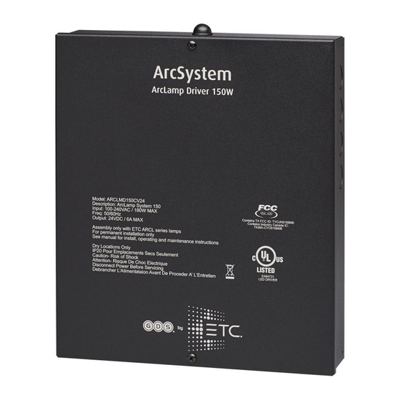
Page 13: Arclamp Driver
Each fixture with ArcLamps installed can be configured to be UL924 listed when wired to an existing emergency response system. ArcLamp drivers are available in RDM models, which control an ArcLamp System with wired DMX/RDM, or models with wireless capability that control an ArcLamp System using ArcMesh wireless protocol. -
Page 14: Arclamp Driver Wiring Specifications
72 W 700 W standard and emergency 6.1 A 146 W Note: It is possible to add a seventh ArcLamp to one channel of an ArcLamp Driver 150 (standard or emergency model) for a total of 25 ArcLamps. ArcLamp System Installation Manual... - Page 15 Note: ArcLamp System circuits may only share the same containment as other house lighting circuits. If the ArcLamp circuit must share the same containment as non-functionally associated...
-
Page 16: Control Specifications
Operation on page 30. ArcLamp System products can be controlled using wired DMX connections to the ArcLamp driver or controlled using wireless ArcMesh protocol. The following graphic shows a basic hybrid ArcLamp system installation with a wireless ArcLamp driver, ArcLamps, transmitter, and a wired DMX console for the main control source. -
Page 17: Prepare For Installation
Chapter 2 Prepare for Installation This chapter details the installation and wire termination for each ArcLamp System product. WARNING: RISK OF ELECTRIC SHOCK! LED Retrofit Kit installation requires knowledge of luminaire electrical systems. If not qualified, do not attempt installation. Contact a qualified electrician. -
Page 18: Installation Location
Installation Location ArcLamp System is designed for use in 0–40°C (32–104°F) ambient temperature. ArcLamp Drivers Note: Mounting hardware and installation location must support the ArcLamp driver, conduit hardware, and all cable required for installation. ArcLamp Rack-Mount Driver Rack-mounted ArcLamp drivers require a 19-inch equipment rack. Each ArcLamp driver requires one unit (1U) of rack space. -
Page 19: Arclamp Installation
ArcLamp Installation ArcLamps install directly to a standard E26, E27, E12, E14, B15, or B22 base. Fixtures with ArcLamps installed must only be powered by an ArcLamp driver. CAUTION: ArcLamp is not suitable for use in enclosed luminaires or in spaces with restricted air flow. -
Page 20: Arclamp Voltage Drop
ArcLamp driver at the ArcLamp. Voltage drop calculations vary by project and are based on the type, length, and gauge of wire used between the ArcLamp driver and ArcLamp. Contact a qualified electrician or ETC technical services for further information. The ArcLamp driver must be installed within a maximum distance of the fixture with ArcLamps installed. -
Page 21: Wall-Mount Driver Installation
Install the ArcLamp Driver on a power distribution system with reliably identified earthed neutral and install a maximum 15 A circuit breaker on the line conductor. ETC recommends installing all wiring to and from wall-mount drivers in grounded metal conduit. The wall-mount ArcLamp Driver accepts 100–277 VAC (150 models) or 100–240 VAC (350 and 700 models), 50/60 Hz. -
Page 22: Wire And Terminal Specifications
The following supplies are required, but not provided, for ArcLamp Driver installation: flexible conduit and conduit fittings • appropriate strain relief connectors for the installation type, as needed • Phillips screwdriver • four each mounting bolts or screws and wall anchors, as needed • ArcLamp System Installation Manual... -
Page 23: Wall-Mount The Driver
Wall-Mount the Driver 1. Using a Phillips screwdriver, remove the two screws securing the cover to the ArcLamp Driver enclosure. Set screws aside for later re-installation. The cover is grounded by a tether to the enclosure. ArcLamp Driver 350 and 700 wall-mount drivers have two hooks inside the cover and •... -
Page 24: Wall-Mount Driver Wiring Overview
B Output channels C Antenna* D DMX input and thru (RJ45) DMX input and thru (eight-pin terminal blocks)† *The antenna is not present on RDM models. †Eight-pin terminal blocks are not present on ArcLamp Driver 150. ArcLamp Driver 700 Wall-Mount ArcLamp System Installation Manual... -
Page 25: Power Input Wiring
Power Input Wiring This section provides power input wiring termination for standard wall-mount ArcLamp Driver models. See Emergency Driver Power Input Wiring on page 46 for instructions to terminate normal sense and emergency power input wiring. ArcLamp 150 Driver Factory Wire Colors Model Color Type... - Page 26 Factory Wire Colors Model Color Type North America green/yellow ground/earth and Europe North America black line/hot North America white neutral Europe brown live Europe blue neutral Wall-Mount ArcLamp Driver 350 and 700 Power Input Detail ArcLamp System Installation Manual...
-
Page 27: Output Wiring To Fixture
Connect the Input Power 1. Make sure power is off at the main circuit breaker. 2. See Wire and Terminal Specifications on page 16 for specification of wire size and strip length. Prepare the wires accordingly. 3. See Push-In Terminal Blocks on the previous page for general instructions on using the push-in terminal blocks. -
Page 28: Dmx In And Dmx Thru
All models of ArcLamp Driver have RJ45 receptacles for RJ45 Pinout Information DMX In and Thru. Description ETC recommends Cat5e (or better) minimum 0.2 mm (24 AWG) conductors terminated to T568B standard. The Data + DMX In and Thru RJ45 connectors on the wall-mount... - Page 29 ArcLamp drivers are not self-terminating. You must terminate the last driver in line with a DMX terminator plug in the RJ45 Thru receptacle. To purchase an RJ45 terminator, please contact your ETC customer service representative and request part number N4086.
- Page 30 Screw terminal connectors are supplied in the DMX Preparation Kit w/Screw Connector (part number 4100A1012) and shipped with your ArcLamp product. Cable other than Belden 9729 may have a different color code for its wire pairs. ArcLamp System Installation Manual...
-
Page 31: Rack-Mount Driver Installation
Chapter 4 Rack-Mount Driver Installation This chapter provides instructions for installing the standard rack-mount models of ArcLamp driver. Instructions for standard wall-mount, emergency wall-mount, and emergency rack-mount drivers are in these chapters: Wall-Mount Driver Installation on page 15 • Emergency Driver Power Input Wiring on page 46 •... -
Page 32: Prepare For Rack-Mount Installation
Mechanical Loading: Only mount the ArcLamp Driver in an equipment rack using the • included ETC rack-mount hardware. Mount in a horizontal orientation to ensure even mechanical loading in the rack, avoiding hazardous or dangerous loading conditions. Circuit Overloading: When installing the ArcLamp Driver in an equipment rack, consider •... -
Page 33: Terminate Wiring
Terminate Wiring Rack-Mount ArcLamp Driver 350 Rack-Mount ArcLamp Driver 700 A Output channel "CH 1" E "DMX In" B Output channel "CH 2" F "DMX Thru" C Output channel "CH 3" G Power input D Output channel "CH 4" Power Input Wiring 1. -
Page 34: Output Wiring To Fixture
This installation technique reduces the number of available output channels. Bridge Output Channels on page 37. Note: A maximum of two output channels can be bridged together on an ArcLamp Driver 700 (standard or emergency model). For more information, see Bridge Output Channels on page 37 ArcLamp System Installation Manual... -
Page 35: Dmx In And Dmx Thru
ArcLamp drivers are not self-terminating. You must terminate the last driver in line with a DMX terminator plug in the RJ45 Thru receptacle. To purchase an RJ45 terminator, please contact your ETC customer service representative and request part number N4086. -
Page 36: Final Installation And Operation
When commissioning a system installation, check all ArcLamp Drivers to ensure that the latest firmware is present. If the firmware is not up to date, upgrade it following the instructions at Updating the Driver Firmware on the facing page. ArcLamp System Installation Manual... -
Page 37: Updating The Driver Firmware
Initial system programming of a wireless ArcLamp system requires a USB commissioning tool (ARC-CT) and existing hardware such as a laptop or desktop computer that is connected to the ArcMesh network. This programming will be carried out by an ETC certified technician at the time of system commissioning and training. - Page 38 Set resets the driver configuration to 0x0090 Defaults default settings. Get returns the current software version Software Version Label 0x00C0 as an ASCII text string. Bootloader Version Get returns the current bootloader 0x00C2 Label version as an ASCII text string. ArcLamp System Installation Manual...
-
Page 39: Maintenance
Maintenance WARNING: RISK OF DEATH BY ELECTRIC SHOCK! Failure to disconnect all power to the system before installation, maintenance, cleaning, or any other system modification could result in serious injury or death. AVERTISSEMENT : RISQUE DE MORT PAR DÉCHARGE ÉLECTRIQUE! Négliger de débrancher toutes les sources d’alimentation du système avant l’installation, l’entretien, le nettoyage ou toute autre modification du système peut causer des blessures graves ou la mort. -
Page 40: Troubleshooting
ArcLamp Driver 700 and ArcLamp Emergency Driver 700 only PSU 1 Fault On: power supply 1 has a fault. Contact ETC Technical Services for assistance. ArcLamp Driver 700 and ArcLamp Emergency Driver 700 only PSU 2 Fault On: power supply 2 has a fault. Contact ETC Technical Services for assistance. -
Page 41: Overload Protection
Overload Protection There are two types of maximum output limit: warning and trip. Contact ETC technical services for assistance with warning and fault conditions. Warning On ArcLamp Driver 350 and 700 models only, the "Channel OK" LED will remain solid on and the Channel Limit LED will light if the current drawn on any channel exceeds the warning limits. -
Page 42: Fade To Warm Behavior
In order to enable fade to warm behavior, ArcLamp systems with ArcMesh must have Fade to Warm Inhibit unchecked in ArcSystem commissioning software at the time of initial system setup. ArcLamp systems with RDM must have the ArcLamp Enable FTW Support parameter set to true. ArcLamp Enable FTW Support on page 32 ArcLamp System Installation Manual... -
Page 43: Appendix A Bridge Output Channels
AVERTISSEMENT : Vous devez utiliser un kit de câblage agréé et fourni par ETC. Ne pontez pas les circuits de sortie avec des fils ou du matériel non agréés. Note: Power wiring should only be installed and terminated by a qualified electrician and should follow standard wiring installation practices. -
Page 44: Voltage Drop
ArcLamp. Voltage drop calculations vary by project and are based on the type, length, and gauge of wire used between the ArcLamp Driver and ArcLamp. Contact a qualified electrician or ETC technical services for further information. The ArcLamp Driver must be installed within a maximum distance of the fixture with ArcLamps installed. -
Page 45: Wall-Mount Bridging Kits
Wall-Mount Bridging Kits 1. 7490K2002 bridging kit for ArcLamp Driver 150 and ArcLamp Emergency Driver 150 for bridging combinations of 2, 3, or 4 channels • two 3-position WAGO® connectors, each with two attached black wires, pre-stripped • one 5-position WAGO connector with four attached black wires, pre-stripped •... -
Page 46: Output Channel Control Switches
Switch block S3 controls the output channel labeled "LED OUT 3" on ArcLamp Driver 150 • or "CH 2" on ArcLamp Driver 350 and 700. Switch block S4 controls the output channel labeled "LED OUT 4" on ArcLamp Driver • 150 or "CH 1" on ArcLamp Driver 350 and 700. ArcLamp System Installation Manual... - Page 47 Switch Functions There are six switches on each switch block. Switch positions 1 and 6 are factory set and should not be adjusted. • Switch positions 2 through 5 are factory set to allow each output to be controlled • individually.
-
Page 48: Example Bridge Configurations
ArcLamp Driver 350 Switch Settings for Four Output Channels Bridged into One Switch Positions Switch Block (Output) S4 (CH 1) S3 (CH 2) Do not adjust from Do not adjust from factory setting factory setting S2 (CH 3) S1 (CH 4) ArcLamp System Installation Manual... - Page 49 Output Channels Bridged in Pairs Bridging pairs of output channels can be done as shown below for control on output channel 1 and output channel 2, or on any pair of output channels as long as the output channels that are electrically connected (bridged) have the same switch block settings. The illustrations and table below show output channel 1 and output channel 2 bridged to form bridged output channel 1 and output channel 3 and output channel 4 bridged to form bridged output channel 3.
- Page 50 ArcLamp Driver 350 Switch Settings for Three Output Channels Bridged into One Switch Positions Switch Block (Output) S4 (CH 1) S3 (CH 2) Do not adjust from Do not adjust from factory setting factory setting S2 (CH 3) S1 (CH 4) ArcLamp System Installation Manual...
-
Page 51: Bridging Procedure
Bridging Procedure The steps below describe how to bridge output channels on wall-mount and rack-mount ArcLamp Driver models. Wall-mount ArcLamp Driver models have four two-position screw- terminal connections located inside the enclosure. Rack-mount ArcLamp Driver 350 and 700 models have four two-position screw-terminal plugs installed in the back of the enclosure. Outputs are labeled "LED OUT 1", "LED OUT 2", "LED OUT 3"... -
Page 52: Appendix B Emergency Driver Power Input Wiring
Each fixture with ArcLamps installed can be configured to be UL924 listed when wired to an existing emergency response system. Note: Fixtures with ArcLamps installed must be hard wired to an ArcLamp Emergency Driver to be considered for UL924 certification. The installation must conform to local and national codes. ArcLamp System Installation Manual... - Page 53 ArcLamp Drivers are available in UL924 listed variants including: ArcLamp Driver 150: 115 W (convection cooled) supplies power for up to 25 individual • 4.4 W ArcLamps ArcLamp Driver 350 (wall-mount or rack-mount): 264 W (single fan) supplies power for up • to 60 individual 4.4 W ArcLamps ArcLamp Driver 700 (wall-mount or rack-mount): 528 W (dual fans) supplies power for up •...
-
Page 54: Wall-Mount Emergency Drivers
C Output channels D Antenna* E DMX input and thru (RJ45) DMX input and thru (eight-pin terminal blocks)† *The antenna is not present on RDM models. †Eight-pin terminal blocks are not present on 150 W models. Wall-Mount ArcLamp Emergency Driver 700 ArcLamp System Installation Manual... -
Page 55: Wall-Mount Emergency Driver Installation
Wall-Mount Emergency Driver Installation CAUTION: RISK OF SHOCK AND FIRE - This unit has more than one power supply connection point. To reduce the risk of electric shock disconnect both the branch circuit-breakers or fuses and emergency power supplies before servicing. ATTENTION : RISQUE D'INCENDIE ET DE CHOC - Cet appareil posséde plusieurs points de connexion d'alimentation. -
Page 56: Terminate Normal Sense Input
Insert the neutral wire (typically white) into the Sense N terminal and tighten the • screw firmly to secure it in place. Insert the line (hot) wire into the Sense L terminal and tighten the screw firmly to • secure it in place. ArcLamp System Installation Manual... - Page 57 Wall-Mount ArcLamp Emergency Driver 350 or 700 Wall-Mount ArcLamp Emergency Driver 350 and 700 have push-in terminal blocks on the "Sense" and "Maintain" inputs. No tools are required to insert wires into the terminal block. Push-In Terminal Blocks on page 20 for an illustration of the push-in terminal blocks.
-
Page 58: Terminate Maintained (Emergency) Input
Insert the neutral wire (typically white) into the Maintained N terminal and • tighten the screw firmly to secure it in place. Insert the line (hot) wire into the Maintained L terminal and tighten the screw • firmly to secure it in place. ArcLamp System Installation Manual... - Page 59 Wall-Mount ArcLamp Emergency Driver 350 and 700 Wall-Mount ArcLamp Emergency Driver 350 and 700 have push-in terminal blocks on the "Sense" and "Maintain" inputs. No tools are required to insert wires into the terminal block. Push-In Terminal Blocks on page 20 for an illustration of the push-in terminal blocks.
-
Page 60: Rack-Mount Emergency Drivers
"Maintained Input" and "Sense Input". With the exception of power input terminations, rack-mount ArcLamp Emergency Driver installation requirements are the same as those of the standard rack-mount ArcLamp Driver. Complete the installation as follows, referencing these sections for installation details: ArcLamp System Installation Manual... - Page 61 Electrical and Wiring Specification on page 25 Review • Review Prepare for Rack-Mount Installation on page 26 • Connect the Normal/Sense input to the normal sense AC power source using the provided • power input cord. Connect the Maintained (Emergency) input to the maintained emergency AC power •...
-
Page 62: Appendix C Emergency Operation And Test
équipement branché à cette unité. Test the ArcSystem ArcLamp emergency system as described: 1. Turn off power at the normal circuit breaker 2. Test the system per ANSI/NFPA 101 Life Safety Code. ArcLamp System Installation Manual... -
Page 63: Appendix Dtx1 Installation
Appendix D TX1 Installation WARNING: RISK OF DEATH BY ELECTRIC SHOCK! Before you begin pulling and terminating wire to the TX1 Transmitter, make sure the main circuit breaker cabinet or other readily accessible input power disconnect device for the normal power input (and emergency power input when used) is locked out and tagged out. -
Page 64: Preparing For Installation
Phillips screwdriver • Four each wall anchors, as needed • Electrical and Wiring Specifications The TX1 Transmitter accepts 100–240 VAC, 50/60 Hz power input. ETC recommends installing all wiring in grounded metal conduit. Wire and Terminal Specifications Conduit Strip Terminal / Connector... -
Page 65: Terminate Wiring
Terminate Wiring DMX IN DATA - front panel LEDs DATA + AUX contact Inputs: DMX OUT ground is common DATA - for both inputs DATA + I/P 1 I/P 2 Power Terminals Fuse TX1 Installation... -
Page 66: Power
DMX is installed in a daisy-chain topology and includes one pair of wires (data +, data -) plus an ISO ground (common). ETC recommends the use of Belden 9729 (or approved equal) wire. For best DMX performance, twist the wires together as close to the terminals as possible. -
Page 67: Dmx Cable Preparation And Termination
DMX IN DATA - On board DMX In and Out DATA + terminal connections Description DATA - common/ground DATA + DMX OUT (GND) I/P 1 I/P 2 AUX INPUTS Data - Data + Detail of TX1 Transmitter with DMX IN connected DMX Cable Preparation and Termination on page 23 DMX Cable Preparation and Termination This instruction assumes preparation of Belden 9729 (or equivalent) cable for termination to the... -
Page 68: Dmx Wire Termination
4. Insert the Data - wire into the "Data -" terminal and tighten the screw. 5. Tug gently on the wires to ensure they are secure. Note: Specific wire colors will vary based on the DMX cable used. ArcLamp System Installation Manual... -
Page 69: Auxiliary Input
Auxiliary Input The AUX closed contact input allows the recall of two additional scenes within the TX1. An installation may utilize the two contact inputs to recall two additional scenes within the TX1 Transmitter when not connected to an external control system, such as a DMX control source. These can be used in conjunction with a fire alarm system or momentary remote push buttons. -
Page 70: Attach Antenna
The master transmitter is indicated by solid red on the LED on the front panel Front Panel LEDs on the previous page labeled "MASTER Tx". See Setup of dual redundancy is done at the time of system commissioning by an ETC certified technician. For more information on this process, contact ETC Technical Services. Maintenance... -
Page 71: Appendix E Compliance
Appendix E Compliance For current and complete compliance information, view the product datasheets at etcconnect.com/Products/Lighting-Fixtures/ArcLamp/Documentation.aspx. FCC Compliance Wireless-capable ArcLamp products comply with Part 15 of the FCC Rules. Operation is subject to the following two conditions: (1) this device may not cause harmful interference, and (2) this device must accept any interference received;... - Page 72 Holzkirchen, DE +49 (80 24) 47 00-0 Rome, IT +39 (06) 32 111 683 Hong Kong +852 2799 1220 Paris, FR +33 1 4243 3535 etcconnect.com Support support.etcconnect.com Contact etcconnect.com/contactETC © 2020 ETC Trademark and patent info: etcconnect.com/ip Product information and specifications subject to change. ETC intends this document to be provided in its entirety. 7490M2130 Rev E Released 2020-12...
Need help?
Do you have a question about the ArcLamp System and is the answer not in the manual?
Questions and answers