AMX NetLinx NXP-TPI/4 Operation/Reference Manual
Touch panel interface 4, firmware version g4
Hide thumbs
Also See for NetLinx NXP-TPI/4:
- Quick start manual (2 pages) ,
- Specifications (1 page) ,
- Operation/reference manual (274 pages)

Related Manuals for AMX NetLinx NXP-TPI/4


Summary of Contents for AMX NetLinx NXP-TPI/4
-
Page 1: Netlinx Touch Panel Interface
Operation/Reference Guide NXP-TPI/4 NetLinx Touch Panel Interface 4 Firmware version G4 D o c u m e n t I D : 0 6 0 - 0 0 4 - 2 6 0 2 Touch Panels I n i t i a l R e l e a s e : / L a s t R e v i s e d : 0 6 / 1 9 / 2 0 0 6... - Page 2 RMA number. AMX is not liable for any damages caused by its products or for the failure of its products to perform. This includes any lost profits, lost savings, incidental damages, or consequential damages. AMX is not liable for any claim made by a third party or by an AMX Dealer for a third party.
-
Page 3: Table Of Contents
Step 5: Re-Installing the TPI/4 Outer Housing... 13 Step 6: Re-Installing TP4 Input Cards ... 13 Removing TP4 Input Cards ... 15 Wiring Guidelines for the NXP-TPI/4 ... 15 Grounding the TPI/4 Unit ... 16 Preparing captive wires... 16 Wiring a power connection ... 16 RS232 Serial Program Port: Connections and Wiring ... - Page 4 Step 3: Verify and Upgrade the TPI/4 firmware via an IP ... 49 Upgrading the TP4 Input Cards via an IP Address ... 51 Step 1: Prepare the cards for firmware transfer... 51 Step 2: Upgrade the input card firmware via an IP ... 52 NXP-TPI/4 NetLinx Touch Panel Interface...
- Page 5 "^" Button Commands ... 88 Text Effect Names ... 108 Button Query Commands ... 109 Panel Runtime Operations ... 118 Input Commands... 122 Embedded Codes ... 124 Panel Setup Commands ... 125 Dynamic Image Commands... 126 NXP-TPI/4 NetLinx Touch Panel Interface Table of Contents...
- Page 6 Input mask next field characters... 136 Input mask operations... 136 Input mask literals ... 136 Input mask output examples ... 137 URL Resources ... 138 Special escape sequences ... 138 List of Touch Monitors tested with the TPI4 ... 139 NXP-TPI/4 NetLinx Touch Panel Interface...
-
Page 7: Product Information
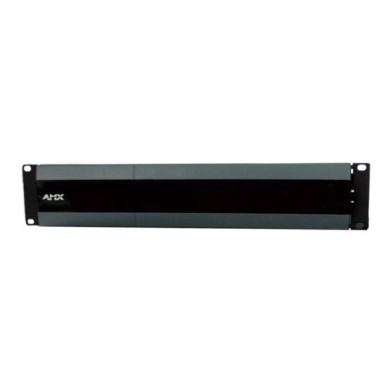
Product Information The NXP-TPI/4 (FIG. 1) is a touch panel interface that supports AMX’s 4th generation graphics (G4) consisting of both rich colors and support for high-contrast images. This G4 interface device is capable of mixing Video/RGB inputs and then combining those inputs with graphics, which can then be displayed on a variety of monitors. -
Page 8: Specifications
Type-B USB host port input connector Input Card Board Connectors FIG. 2 TP4 Input Card connectors (front and rear views) Specifications The following table lists the specifications for the NXP-TPI/4 and its available input modules. Specifications Dimensions (HWD): NXP-TPI/4 (FG2275-01) TP4-VID (FG2275-10) - Page 9 • 64 MB SDRAM (upgradeable to 256 MB) • 64 MB Compact Flash (upgradeable to 1 GB - factory programmed) • See the Other AMX Equipment: section on page 6 for component upgrade information. • 48000Hz, 44100Hz, 32000Hz, 24000Hz, 22050Hz, 16000Hz, 12000Hz, 11025Hz, and 8000Hz.
-
Page 10: Netlinx Touch Panel Interface
Note: Input slots are universal. You can use any combination of input modules in any of the four input slots. The NXP-TPI/4 handles multiple input resolutions and refresh rates. • RS-232 (DB9) 9-pin serial port. Used to connect a pointer device such as a touch screen. - Page 11 TP4 Input Cards: TP4-VID: TP4-RGB: NXP-TPI/4 NetLinx Touch Panel Interface • 2 PS/2 ports for Keyboard and Mouse control. • 2 USB ports for Keyboard and Mouse control. The two Type-A USB ports can connect up to two external keyboard or mouse devices for use with Virtual PC applications.
- Page 12 • Storage Humidity: 0% to 85% RH Non-Condensing • 2-pin PWR connector (41-5025) • Assembly Kit (Four-#10-32 screws and Four-#10 washers) (KA0001) • NXF Bezel with AMX Logo (MA2001-11) • NXP-TPI/4 Faceplate (MA2001-11) • NXP-TPI/4 Quick Start Guide (93-2275) • Rack Ear brackets (Left/Right) for shelf, wall, and under-table mounting (62-2275-07) •...
-
Page 13: Tpi/4 Front And Rear Components
TPI/4 Front and Rear Components FIG. 3 shows the components on both the front and rear of the NXP-TPI/4. PWR LED DB9 SERIAL port Front View Rear View Input Slot 4 DB9 Touch Input port FIG. 3 NXP-TPI/4 (front and rear views) -
Page 14: Ethernet Ports Used By The Tpi/4
USB mouse. If a USB keyboard has been connected, only on-screen keyboards and keypads will reflect any external keystrokes sent from the external USB keyboard. Standard Port # 1319 (UDP/TCP) ICMP 23 (TCP) NXP-TPI/4 NetLinx Touch Panel Interface... -
Page 15: Installation
Installation The NXP-TPI/4 is delivered from the factory with four installed input card covers (FIG. 4). The unit is capable of supporting any combination of up to four TP4 input cards. The two different types of input modules are the TP4-RGB and TP4-VID. -
Page 16: Step 1: Removing Input Card Covers
6. Carefully remove the outer housing by gently sliding the top housing away from the front of the unit. The removal allows you to view the internal memory located on the main board (FIG. 6). Blank card covers Round screws Housing screws NXP-TPI/4 NetLinx Touch Panel Interface... -
Page 17: Step 3: Upgrading The Internal Exm Memory Module
5. Remove the memory module upgrade from the anti-static bag. 6. Firmly grasp the new memory module (from the edges) and insert the pins (at a 45° angle) into the opening on the connector. NXP-TPI/4 NetLinx Touch Panel Interface Pull tabs outward Connector... -
Page 18: Step 4: Upgrading The Internal Compact Flash Card
Compact Flash card and securely attached to the connector. 7. Follow the procedures outlined in the following section to complete the upgrade process and resecure the outer housing back onto the TPI/4. On-board Compact Flash connector NXP-TPI/4 NetLinx Touch Panel Interface... -
Page 19: Step 5: Re-Installing The Tpi/4 Outer Housing
5. Carefully align the male pins (on the card) and female (on the TPI/4 circuit board) connector. 6. Connect the input card by inserting the male pins vertically down onto the female input connectors on the motherboard, as shown in FIG. 9. NXP-TPI/4 NetLinx Touch Panel Interface Installation... - Page 20 10. Screw-in (clockwise) the four screws (per card) to both the top and rear of the unit to secure each card firmly to the TPI/4 (along the ends of the inserted input card) (FIG. 9). Input card connectors (male) Motherboard card connectors (female) Flat phillips-head screws Housing screws Grounding bolt NXP-TPI/4 NetLinx Touch Panel Interface...
-
Page 21: Removing Tp4 Input Cards
COMMUNICATION. Wiring Guidelines for the NXP-TPI/4 The NXP-TPI/4 requires a 12 VDC-compliant power supply to provide power to the TPI/4 via the 2-pin 3.5 mm mini-Phoenix PWR connector. The incoming PWR and GND wires from the power supply must be connected to the corresponding locations within the PWR connector. -
Page 22: Grounding The Tpi/4 Unit
2. Tighten the clamp to secure the two wires. Do not tighten the screws excessively; doing so may strip the threads and damage the connector. 3. Verify the connection of the 2-pin 3.5 mm mini-Phoenix to the external 12 VDC-compliant power supply. Power Supply NXP-TPI/4 NetLinx Touch Panel Interface... -
Page 23: Rs232 Serial Program Port: Connections And Wiring
(female) to DB9 NullModem (female) cable to connect the Program port on the TPI/4 to the rear RS-232 COM port on the PC. Another option is to use a Full NullModem (male/male) connector to bridge the gap between to DB9 female connectors. NXP-TPI/4 NetLinx Touch Panel Interface Signal Female... -
Page 24: Vga Port: Connections And Wiring
Vertical synchronization signal Not used DB9 A DB9 B DB9 B Signal 6 + 1 DSR + Carrier Detect 6 +1 VGA HD-15 (male) connector DB9 female connector side A DB9 female connector side B NXP-TPI/4 NetLinx Touch Panel Interface... -
Page 25: Icsnet Port: Connections And Wiring
ICSNet Port: Connections and Wiring The following tables show the signal and pinout/pairing information used for ICSNet RJ-45 data connections. ICSNet uses a standard CAT5 Ethernet cable to provide communication between the NXP-TPI/4 touch panel interface and the NetLinx Master. ICSNet RJ-45 Signals Signal-Master... -
Page 26: Hooking-Up The Tpi/4 Rear Cable Connections
4 --------- 5 Blue-White 6 --------- 6 Green 7 --------- 7 7 --------- 8 Brown-White 8 --------- 8 Brown 1 2 3 4 5 6 7 8 1 2 3 4 5 6 7 8 NXP-TPI/4 NetLinx Touch Panel Interface... -
Page 27: Using The Tp4-Rgb Card For Pass-Thru Control
TPI/4 unit 2. Disconnect any incoming power connector from the rear of the TPI/4. 3. Connect either a PS/2 or USB mouse to the rear of the TPI/4 unit (as seen in FIG. 13). NXP-TPI/4 NetLinx Touch Panel Interface Installation... - Page 28 Initially positioning the TPI/4 incoming video can reduce any later adjustments of the video through the RGB Setup page (H-position, V-position, H-size, etc.). From USB Mouse input device (used to control actions on computer pages routed for viewing through monitor) Connect to CRT/monitor VGA output NXP-TPI/4 NetLinx Touch Panel Interface...
-
Page 29: Using A Touch Panel For Both Mouse And Touch Pass-Thru Control
TPI/4 must then have power cycled so that it can detect the newly connected mouse. This detection is most useful when using a CRT monitor. NXP-TPI/4 NetLinx Touch Panel Interface From USB Mouse input device... - Page 30 12. If necessary, use the panel’s video adjust buttons to align the incoming video signal to fit into the available screen area. Initially positioning the TPI/4 incoming video can reduce any later adjustments of the video through the RGB Setup page (H-position, V-position, H-size, etc.). NXP-TPI/4 NetLinx Touch Panel Interface...
-
Page 31: Mounting The Tpi/4 Into An Equipment Rack
FIG. 15 Installing the NXP-TPI/4 into an equipment rack 3. Connect any applicable wires to the NXP-TPI/4. Refer to the Hooking-up the TPI/4 Rear Cable Connections section on page 20 for wiring diagrams and pinout descriptions. 4. Connect the terminal NetLinx wiring to the Central Controller, RS-232, Ethernet, ICSNet, USB, and optional video/graphic wiring to the source equipment. -
Page 32: Other Mounting Options
Installation 8. The transparent plastic AMX cover can be removed to gain better access and visibility of the front LEDs and pushbuttons. Other Mounting Options The TPI/4 comes included with rack ears that can be rotated 90° in any direction to accommodate several different mounting options, including tabletop, under/over the table, and vertical wall mounting. -
Page 33: Tpi/4 And Panel Interface Setup
The TPI/4 has not been factory setup with specific touch panel pages. The first splash screen that appears (FIG. 17) indicates the TPI/4 is receiving power, loading firmware, and preparing to display the default touch panel page. When the panel is ready, the AMX Splash Screen is replaced by the Initial Panel Setup page. -
Page 34: Step 1: Setting The Output Resolution On The Tpi/4
Currently selected output resolution • 800 x 600 @72Hz • 1024 x 768 @75Hz • 800 x 600 @75Hz • 1280 x 1024 @60Hz (highest setting) • 1024 x 768 @60Hz • 1024 x 768 @70Hz NXP-TPI/4 NetLinx Touch Panel Interface... -
Page 35: Step 2: Setting The Touch Drivers
2. Press the front panel TOUCH button to cycle through the series of available touch input drivers (firmware build 67 or higher) shown in the following list: Verify that the selected touch driver matches the connected touch panel or monitor. NXP-TPI/4 NetLinx Touch Panel Interface TPI/4 and Panel Interface Setup ®... - Page 36 Refer to the List of Touch Monitors tested with the TPI4 section on page 139 for a comprehensive list of Touch Monitors that have been tested with the TPI4. Description: Selected when using an AMX DL15A touch panel. Selected when using a Cirque touch panel or other compatible touch device driver.
-
Page 37: Step 3: Calibrating The Tpi/4
1. Press the front panel SETUP button to open the Setup page. 2. Follow the procedures in the Configuring Communication section on page 33 to configure the communication parameters for the NXP-TPI/4. NXP-TPI/4 NetLinx Touch Panel Interface TPI/4 and Panel Interface Setup... - Page 38 TPI/4 and Panel Interface Setup NXP-TPI/4 NetLinx Touch Panel Interface...
-
Page 39: Configuring Communication
When using multiple TPI/4s within a NetLinx System, remember to assign unique Device Number values to each panel so that all assigned panels appear in the System listing for the target Master. NXP-TPI/4 NetLinx Touch Panel Interface Configuring Communication Connection Status... - Page 40 Connection page (FIG. 22) and begin configuring the communication settings on the TPI/4 to match those of the target Master. TPI/4 connection information MAC Address from unit is factory set to a unique address FIG. 22 System Connection page NetLinx Master’s connection information NXP-TPI/4 NetLinx Touch Panel Interface...
-
Page 41: Master Connection - Using Icsnet
8. Press the Protected Setup button on the touch panel to return to the Protected Setup page. 9. Press the on-screen Reboot button from the Protected Setup page to both save any changes and restart the TPI/4. NXP-TPI/4 NetLinx Touch Panel Interface Configuring Communication... -
Page 42: Configuring A Wired Ethernet Connection
Check with your System Administrator for a pre-reserved Static IP Address assigned to the TPI/4. This address must be obtained before Static assignment of the TPI/4 continues. 3. Toggle the DHCP/Static field (from the IP Settings section) until the choice cycles to Static. NXP-TPI/4 NetLinx Touch Panel Interface... -
Page 43: Step 2: Choosing A Master Connection Mode Setting
1. Verify the TPI/4 has been configured to communicate through an Ethernet cable connected from the rear of the TPI/4 to a valid Ethernet Hub. Before commencing, verify you are using the latest NetLinx Master firmware. NXP-TPI/4 NetLinx Touch Panel Interface Configuring Communication... -
Page 44: Master Connection - Virtual Master Communication Over Ethernet
1. Verify the TPI/4 has been configured to communicate through an Ethernet cable connected from the TPI/4 to a valid Ethernet Hub. 2. Launch NetLinx Studio 2 (default location is Start > Programs > AMX Control Disc > NetLinx Studio 2 > NetLinx Studio 2). - Page 45 Setup page and continue with the setup process and proceed to the Setup page. 14. Select Protected Setup > System Connection (located on the lower-left) to open the System Connection page (FIG. 26). NXP-TPI/4 NetLinx Touch Panel Interface Configuring Communication IP Addresses of computer (also obtained by using the Start >...
-
Page 46: Master Connection Section - Netlinx Master Ethernet Ip Address - Url Mode
By selecting URL, the System Number field becomes read-only (grey) because the TPI/4 pulls this value directly from the communicating target Master (virtual or not). A virtual Master system value can be set within the active AMX software applications such as: NetLinx Studio, TPD4, or IREdit. -
Page 47: Master Connection Section - Netlinx Master Ethernet Ip Address - Listen Mode
8. Click Add and enter the IP Address of the TPI/4 into the Add URL dialog box. 9. Click OK to enter your IP Address and add it to the list. 10. Click Done once you are finished adding your TPI/4 information to the list. NXP-TPI/4 NetLinx Touch Panel Interface Configuring Communication... -
Page 48: Master Connection Section - Netlinx Master Ethernet Ip Address - Auto Mode
Refer to the G4 Web Control Page section on page 99 for more detailed information. Verify your NetLinx Master (ME260/64 or NI-Series) has been installed with the latest firmware KIT file from www.amx.com. Refer to your NetLinx Master Instruction Manual for more detailed information on the use of the new web-based NetLinx Security. - Page 49 14. Press the Web Control Port field to open the Web Port Number keypad. 15. Within the keypad, enter a unique numeric value to be assigned to the port the VNC Web Server is running on. The default value is 5900. NXP-TPI/4 NetLinx Touch Panel Interface Configuring Communication...
-
Page 50: Using Your Netlinx Master To Control The Unit
If the Master has been previously configured for secured communication, click OK to accept the AMX SSL certificate (if SSL is enabled) and then enter a valid username and password into the fields within the Login dialog. 4. Click OK to enter the information and proceed to the Master’s Manage WebControl Connections window. - Page 51 Wired Ethernet - System Connection > IP Settings section within the IP Address field. If you do not get this field continue to step 9. NXP-TPI/4 NetLinx Touch Panel Interface Configuring Communication Compatible...
- Page 52 A left-mouse click on the computer-displayed panel page equates to an actual touch on the target G4 panel page. IP Address of touch panel - obtained from IP Settings section of the System Connection page NXP-TPI/4 NetLinx Touch Panel Interface...
-
Page 53: Upgrading Tpi/4 Firmware
NetLinx Master instruction manual to use an address. Note the IP Address and Gateway information. 2. Launch NetLinx Studio 2 (default location is Start > Programs > AMX Control Disc > NetLinx Studio 2 > NetLinx Studio 2). - Page 54 16. Click the OnLine Tree tab in the Workspace window to view the devices on the System. The default System value is one. 17. Right-click on the Empty Device Tree/System entry and select Refresh System to re-populate the list. List of previously saved IP Addresses NXP-TPI/4 NetLinx Touch Panel Interface...
-
Page 55: Step 2: Prepare The Tpi/4 For Communication Via An Ip
By selecting URL, the System Number field becomes read-only (grey) because the panel pulls this value directly from the communicating target Master (virtual or not). A virtual Master system value can be set within the active AMX software applications such as: NetLinx Studio, TPD4, or IREdit. - Page 56 Master, and populates the System list with devices on your particular system. Selected Firmware file Device value and System number must match the values listed in the Workspace window Description field for selected KIT file Firmware download status NXP-TPI/4 NetLinx Touch Panel Interface...
-
Page 57: Upgrading The Tp4 Input Cards Via An Ip Address
Upgrading the TP4 Input Cards via an IP Address The v 2.XX firmware KIT file (available at www.amx.com) upgrades any connected TP4 Input cards. If there is both a TP4-RGB and TP4-VID card in a TPI/4, then the KIT file updates the firmware on both cards. -
Page 58: Step 2: Upgrade The Input Card Firmware Via An Ip
The default TPI/4 panel value is 2275. The TP4 Input Cards will not appear on the system listing. 4. Locate the latest firmware file from the www.amx.com > Tech Center > Downloadable Files > Firmware Files > NXP-TPI/4 - Input Card Firmware section of the website. - Page 59 15. Confirm the current firmware version on the cards by pressing the Video Adjustment button and then the corresponding Slot # button of the target TP4 card. NXP-TPI/4 NetLinx Touch Panel Interface Selected Battery Base Firmware file Device value and System number...
- Page 60 Upgrading TPI/4 Firmware NXP-TPI/4 NetLinx Touch Panel Interface...
-
Page 61: Firmware Pages And Descriptions
NXP-TPI/4 Setup Navigation Buttons FIG. 39 G4 Setup Navigation Buttons These Navigation Buttons are specific to the NXP-TPI/4 and include the device specific elements described in the following table: G4 Setup Navigation Button Elements Project Information: Panel Information:... -
Page 62: Setup Page
The page (FIG. 40) centers around the basic properties used by the touch device connected to the NXP-TPI/4 such as: Connection Status of the TPI/4, Display Timeout, Inactivity Page Flip Time, and Inactivity page file information for the TPI/4 device. - Page 63 Timeout: Inactivity Page Flip Timeout: NXP-TPI/4 NetLinx Touch Panel Interface Displays whether the G4 device is communicating externally, the encryption status of the communicating Master, what connection type is being used (Ethernet or ICSNet), and what System the unit is a part of.
-
Page 64: Project Information Page
• A Lock only appears on the icon if the TPI/4 has established a connection with a currently secured target Master (requiring a username and password). Displays the name of the TPDesign4 project file downloaded to the NXP-TPI/4. Displays the designer information. -
Page 65: Panel Information Page
Displays the type of G4 device being used. Displays the G4 firmware version being used by the G4 device. • Verify you have the latest version from www.amx.com. Displays the setup port information/value being used by the TPI/4. Displays the high port (port count) value for the TPI/4. -
Page 66: Time & Date Setup Page
• The Get Time/Date button retrieves the Time and Date information from the Master. • The Set Time/Date button sets the Master to retain and save any time/date modifications made on the Time and Date Setup page. NXP-TPI/4 NetLinx Touch Panel Interface Date Display fields... -
Page 67: Volume Page
The elements of the Volume page are described in the table below: Volume Page Elements Exit: Connection Status icon: NXP-TPI/4 NetLinx Touch Panel Interface • These fields display the time in three formats: STANDARD, STANDARD AM/PM, and 24 HOUR. • These fields display the calendar date information in several different formats. -
Page 68: Supported Sampling Rates For Wav
Sets the unit to play either the default Button Hit sound (when you touch an active button) and/or the default Button Miss sound (when you touch a non-active button or any area outside of the active button). • 16000 Hz • 12000 Hz • 11025 Hz • 8000 Hz NXP-TPI/4 NetLinx Touch Panel Interface... -
Page 69: Video Adjustment - Video Adjustment
Connection Status icon: Settings: Video Settings: Status: Version: NXP-TPI/4 NetLinx Touch Panel Interface Incoming Video signal Once done making your screen adjustments, SAVE SETTINGS. Saves the changes and returns you to the previously active touch panel page. This visual display of the connection status allows the user to have a current update of the TPI/4’s connection status regardless of what page is currently... -
Page 70: Video Adjustment - Rgb Setup
• Range = 0 - 255, default = 128. Firmware version of TP4-RGB card Output resolution Once you are done making your adjustments, click SAVE SETTINGS. Incoming signal shown in the background Pressing this area activates the Full Screen Edit mode NXP-TPI/4 NetLinx Touch Panel Interface... - Page 71 Red Brightness Green Brightness Blue Brightness NXP-TPI/4 NetLinx Touch Panel Interface Saves the changes and returns you to the previously active touch panel page. This visual display of the connection status allows the user to have a current update of the TPI/4’s connection status regardless of what page is currently active.
-
Page 72: Adjusting The Incoming Image On The Rgb Adjustment Page
• Pressing the bar launches a draggable popup of all Adjustment buttons over the full screen image. • This popup allows you to view and alter the displayed image without having the image blocked by the upper section of settings buttons. NXP-TPI/4 NetLinx Touch Panel Interface... - Page 73 TP4-RGB card. Cycling power to the panel before saving your settings can cause your pages to shift back to their original locations. 12. Press the Back button to return to the Setup page. NXP-TPI/4 NetLinx Touch Panel Interface Firmware Pages and Descriptions On-screen image controls...
-
Page 74: Protected Setup Navigation Buttons
Setup Navigation Buttons FIG. 49 G4 Protected Setup Navigation Buttons These Navigation Buttons are specific to the NXP-TPI/4 device and include the device specific elements described in the following table: G4 Protected Setup Navigation Button Elements G4 Web Control: Passwords:... -
Page 75: Protected Setup Page
Protected Setup Page The Protected Setup page (FIG. 50) centers around the properties used by the NXP-TPI/4 to communicate with the NetLinx Master. Enter the factory default password (1988) into the password keypad to access this page. FIG. 50 Protected Setup page... - Page 76 The following list shows the series of available touch input drivers that are selectable by using the TOUCH button on the front panel of the TPI/4: - AMXDL15A: Selected when using an AMX DL15A touch panel. ® - Cirque: Selected when using a Cirque compatible touch device driver.
- Page 77 • The Remove User Pages button allows you remove all current TPD4 touch panel pages currently on the TPI/4 (including the pre-installed AMX Demo pages). - Pressing this button launches a Confirmation dialog (FIG. 51) which asks you to confirm your selection.
-
Page 78: G4 Web Control Page
TPI/4’s connection status regardless of what page is currently active. • A Lock only appears on the icon if the TPI/4 has established a connection with a currently secured target Master (requiring a username and password). NXP-TPI/4 NetLinx Touch Panel Interface... - Page 79 G4 Web Control page with the new web-based NetLinx Security application. NXP-TPI/4 NetLinx Touch Panel Interface Sets the IP communication values for the TPI/4 and contains: • The Enable/Enabled button allows you to toggle between the two G4 activation settings: - Enable - deactivates the G4 Web Control feature on the TPI/4.
-
Page 80: Password Setup Page
The request to touch the crosshairs is the first on-screen message Calibration successful is the second on-screen message that appears after the calibration process is completed On-screen crosshairs used for calibration of the touch device NXP-TPI/4 NetLinx Touch Panel Interface... -
Page 81: System Connection Page
• A Lock only appears on the icon if the TPI/4 has established a connection with a currently secured target Master (requiring a username and password). Sets the IP communication values for the NXP-TPI/4 and contains: Sets the G4 device to either DHCP or Static communication modes. - Page 82 Sets the speed of the Ethernet connection to the TPI/4. • Choices are: Auto, 10 Half Duplex, 10 Full Duplex, 100 Half Duplex, or 100 Full Duplex. Displays a read-only field that is factory set by AMX for the built-in Ethernet interface. Sets the NetLinx Master communication values: Sets the NetLinx Master to communicate to the TPI/4 via either ICSNet or Ethernet.
-
Page 83: Programming
Variable: Example: Adds the popup page ’Popup1’ to the popup group ’Group1’. NXP-TPI/4 NetLinx Touch Panel Interface "'@APG-<popup page name>;<popup group name>'" popup page name = 1 - 50 ASCII characters. Name of the popup page. popup group name = 1 - 50 ASCII characters. Name of the popup group. - Page 84 = Refers to the popup effect names being used. SEND_COMMAND Panel,"'@PHE-Popup1;Slide Left'" "'@PHP-<popup page name>;<x coordinate>,<y coordinate>'" popup page name = 1 - 50 ASCII characters. Name of the page the popup is displayed SEND_COMMAND Panel,"'@PHP-Popup1;75,0'" NXP-TPI/4 NetLinx Touch Panel Interface...
- Page 85 Toggles the popup page ’Popup1’ on the ’Main’ page from one state to another (On/Off). Example 2: SEND_COMMAND Panel,"'@PPG-Popup1'" Toggles the popup page ’Popup1’ on the current page from one state to another (On/Off). NXP-TPI/4 NetLinx Touch Panel Interface Programming...
- Page 86 = 1 - 50 ASCII characters. Name of the popup page. page name = 1 - 50 ASCII characters. Name of the page the popup is displayed On. SEND_COMMAND Panel,"'@PPN-Popup1;Main'" SEND_COMMAND Panel,"'@PPN-Popup1'" NXP-TPI/4 NetLinx Touch Panel Interface...
- Page 87 = 1 - 50 ASCII characters. Name of the page the popup is displayed page. show effect time = Given in 1/10ths of a second. Example: SEND_COMMAND Panel,"'@PST-Popup1;50'" Sets the Popup1 show effect time to 5 seconds. NXP-TPI/4 NetLinx Touch Panel Interface Programming...
- Page 88 = 1 - 50 ASCII characters. Name of the popup page. page name = 1 - 50 ASCII characters. Name of the page the popup is displayed On. SEND_COMMAND Panel,"'PPOG-Popup1;Main'" SEND_COMMAND Panel,"'PPOG-Popup1'" NXP-TPI/4 NetLinx Touch Panel Interface...
-
Page 89: Programming Numbers
Very Dark Red Very Light Orange Light Orange Orange Medium Orange Dark Orange Very Dark Orange Very Light Yellow Light Yellow Yellow Medium Yellow Dark Yellow Very Dark Yellow Very Light Lime Light Lime NXP-TPI/4 NetLinx Touch Panel Interface Green Blue Programming... - Page 90 Very Light Blue Light Blue Blue Medium Blue Dark Blue Very Dark Blue Very Light Purple Light Purple Purple Medium Purple Dark Purple Very Dark Purple Very Light Magenta Light Magenta Magenta Medium Magenta Green Blue NXP-TPI/4 NetLinx Touch Panel Interface...
-
Page 91: Font Styles And Id Numbers
Courier New Courier New Courier New Courier New Courier New Courier New Courier New Courier New AMX Bold AMX Bold AMX Bold NXP-TPI/4 NetLinx Touch Panel Interface Green Size Font ID # Font type Arial Arial Arial Arial Arial Arial... -
Page 92: Border Styles And Programming Numbers
Border styles Circle 95 Circle 105 Circle 115 Circle 125 Circle 135 Circle 145 Circle 155 Circle 165 Circle 175 Circle 185 Circle 195 Cursor Bottom Cursor Bottom with Hole Cursor Top Cursor Top with Hole NXP-TPI/4 NetLinx Touch Panel Interface... - Page 93 Diamond 175 Diamond 185 Diamond 195 Double Bevel -L Double Bevel -M Double Bevel -S Double Line Fuzzy NXP-TPI/4 NetLinx Touch Panel Interface Border styles Glow-L Glow-S Help Down Neon Active -L Neon Active -S Neon Inactive -L Neon Inactive -S...
-
Page 94: Button Commands
Menu Left Rounded 115 Menu Left Rounded 125 Menu Left Rounded 135 Menu Left Rounded 145 Menu Left Rounded 155 Menu Left Rounded 165 Menu Left Rounded 175 Menu Left Rounded 185 Menu Left Rounded 195 NXP-TPI/4 NetLinx Touch Panel Interface... - Page 95 Example: SEND_COMMAND Panel,"'^BAU-520,1,00770062'" Appends Unicode text '00770062' to the button’s OFF state. NXP-TPI/4 NetLinx Touch Panel Interface Stan[dardPage] - Flip to standard page Prev[iousPage] - Flip to previous page Show[Popup] - Show Popup page Hide[Popup] - Hide Popup page...
- Page 96 1 = Off state and 2 = On state). color value = Refer to theRGB Values for all 88 Basic Colors table on page 83 for more information. SEND_COMMAND Panel,"'^BCF-500.504&510.515,1,12'" SEND_COMMAND Panel,"'^BCF-500.504&510.515,1,Yellow'" SEND_COMMAND Panel,"'^BCF-500.504&510.515,1,#F4EC0A63''" SEND_COMMAND Panel,"'^BCF-500.504&510.515,1,#F4EC0A'" NXP-TPI/4 NetLinx Touch Panel Interface...
- Page 97 = (None, Channel, Invert, On (Always on), Momentary, and Blink). Example: SEND_COMMAND Panel,"'^BFB-500,Momentary'" Sets the Feedback type of the button to 'Momentary'. NXP-TPI/4 NetLinx Touch Panel Interface Image Layer = 2 Icon Layer Text Layer Border Layer = 5...
- Page 98 = 1 - 256 for multi-state buttons (0 = All states, for General buttons 1 = Off state and 2 = On state). number of lines = 0 - 240. SEND_COMMAND Panel,"'^BLN-500,55'" NXP-TPI/4 NetLinx Touch Panel Interface...
- Page 99 315 onto the OFF state border, font, Text, bitmap, icon, fill color and text color of the button with a variable text address of 150. NXP-TPI/4 NetLinx Touch Panel Interface BR - Border CB - Border Color...
- Page 100 BUT the 0 (zero) is absolute and followed by ’,<left>,<top>’ ’%JI<alignment of icon 0-9>’ = As shown the above telephone keypad alignment chart, BUT the 0 (zero) is absolute and followed by ’,<left>,<top>’ NXP-TPI/4 NetLinx Touch Panel Interface...
- Page 101 ’%VN<network name>’ = Set network connection name. ’%VP<password>’ = Set the network connection password. Example: SEND_COMMAND Panel,"'^BMF-500,1,%B10%CFRed%CB Blue %CTBlack%Ptest.png'" Sets the button OFF state as well as the Border, Fill Color, Border Color, Text Color, and Bitmap. NXP-TPI/4 NetLinx Touch Panel Interface Programming...
- Page 102 1 = Off state and 2 = On state). name of bitmap/picture = 1 - 50 ASCII characters. SEND_COMMAND Panel,"'^BMP-500.504&510.515,1,bitmap.png'" "'^BNC-<vt addr range>,<command value>'" variable text address range = 1 - 4000. command value = (0= clear, 1= clear all). SEND_COMMAND Panel,"'^BNC-973,0'" NXP-TPI/4 NetLinx Touch Panel Interface...
- Page 103 = 0 (invisible) - 255 (opaque). Example: SEND_COMMAND Panel,"'^BOP-500.504&510.515,1,200'" Example 2: SEND_COMMAND Panel,"'^BOP-500.504&510.515,1,#C8'" Both examples set the opacity of the buttons with the variable text range of 500-504 and 510-515 to 200. NXP-TPI/4 NetLinx Touch Panel Interface Programming...
- Page 104 Sets the border by number (#10) to those buttons with the variable text range of 500-504 & 510-515. Sets the border by name (AMX Elite) to those buttons with the variable text range of 500-504 & 510-515. The border style is available through the TPDesign4 border-style drop-down list. Refer to theTPD4 Border Styles by Name table on page 86 for more information.
- Page 105 1 = Off state and 2 = On state). sound name = (blank - sound cleared, not matched - button sound not changed). Example: SEND_COMMAND Panel,"'^BSO-500,1&2,music.wav'" Assigns the sound 'music.wav' to the button Off/On states. NXP-TPI/4 NetLinx Touch Panel Interface Programming...
- Page 106 = 1 - 256 for multi-state buttons (0 = All states, for General buttons 1 = Off state and 2 = On state). word wrap = (0=Off and 1=On). Default is Off. SEND_COMMAND Panel,"'^BWW-500,1,1'" NXP-TPI/4 NetLinx Touch Panel Interface...
- Page 107 The Font ID is generated by TPD4 and is located in TPD4 through the Main menu. Panel > Generate Programmer's Report >Text Only Format >Readme.txt. NXP-TPI/4 NetLinx Touch Panel Interface Stan[dardPage] - Flip to standard page Prev[iousPage] - Flip to previous page...
- Page 108 = 1 - 65535 (bargraph upper limit range). SEND_COMMAND Panel,"'^GLH-500,1000'" "'^GLL-<vt addr range>,<bargraph low>'" variable text address range = 1 - 4000. bargraph limit range = 1 - 65535 (bargraph lower limit range). SEND_COMMAND Panel,"'^GLL-500,150'" NXP-TPI/4 NetLinx Touch Panel Interface...
- Page 109 = 1 - 4000. bargraph slider name = see table below. Example: SEND_COMMAND Panel,"'^GSN-500,Ball'" Changes the bargraph slider name or the Joystick cursor name to ’Ball’. NXP-TPI/4 NetLinx Touch Panel Interface Bargraph Slider Names: None Ball Circle -M...
- Page 110 = 1 - 256 for multi-state buttons (0 = All states, for General buttons 1 = Off state and 2 = On state). new icon alignment = Value of 1 - 9 corresponds to the following locations: Zero can be used for an absolute position SEND_COMMAND Panel,"'^JSI-500.504&510.515,1&2,1'" NXP-TPI/4 NetLinx Touch Panel Interface...
- Page 111 = 1 - 4000. range. command value = (0= hide, 1= show). Example: SEND_COMMAND Panel,"'^SHO-500.504&510.515,0'" Hides buttons with variable text address range 500-504 & 510-515. NXP-TPI/4 NetLinx Touch Panel Interface Zero can be used for an absolute position Programming...
- Page 112 = 1 - 256 for multi-state buttons (0 = All states, for General buttons 1 = Off state and 2 = On state). new text = 1 - 50 ASCII characters. SEND_COMMAND Panel,"'^TXT-500.504&510.515,1&2,Test Only'" NXP-TPI/4 NetLinx Touch Panel Interface...
- Page 113 1, (for which the character code is 0041 Hex), send the following command: Note: Unicode is always represented in a HEX value. TPD4 generates (through the Text Enter Box dialog) unicode HEX values. Refer to the TPDesign4 Instruction Manual for more information. NXP-TPI/4 NetLinx Touch Panel Interface SEND_COMMAND TP,"'^UNI-1,0,0041'" Programming...
-
Page 114: Text Effect Names
• Hard Drop Shadow 4 with outline • Hard Drop Shadow 5 with outline • Hard Drop Shadow 6 with outline • Hard Drop Shadow 7 with outline • Hard Drop Shadow 8 with outline NXP-TPI/4 NetLinx Touch Panel Interface... -
Page 115: Button Query Commands
Custom Event Fields Field Uint Flag slong value1 slong value2 slong value3 string text text length (string encode) NXP-TPI/4 NetLinx Touch Panel Interface // Text // Bitmap // Icon // Text Justification // Bitmap Justification // Icon Justification // Font... - Page 116 Text length - Color name length (should be 9) SEND COMMAND Panel,"'?BCB-529,1'" ButtonGet Id = 529 Type = 1011 Flag = 0 VALUE1 = 1 VALUE2 = 9 VALUE3 = 0 TEXT = #222222FF TEXT LENGTH = 9 NXP-TPI/4 NetLinx Touch Panel Interface...
- Page 117 SEND COMMAND Panel,"'?BCT-529,1'" Gets the button 'OFF state' text color information. The result sent to Master would be: NXP-TPI/4 NetLinx Touch Panel Interface Flag - Zero Value1 - Button state number Value2 - Actual length of string (should be 9)
- Page 118 Text - Blank Text length - Zero SEND COMMAND Panel,"'?BOP-529,1'" ButtonGet Id = 529 Type = 1015 Flag = 0 VALUE1 = 1 VALUE2 = 200 VALUE3 = 0 TEXT = TEXT LENGTH = 0 NXP-TPI/4 NetLinx Touch Panel Interface...
- Page 119 SEND COMMAND Panel,"'?BWW-529,1'" Gets the button 'OFF state' word wrap flag status information. The result sent to the Master would be: NXP-TPI/4 NetLinx Touch Panel Interface Flag - Zero Value1 - Button state number Value2 - Actual length of string...
- Page 120 Text - Blank Text length - Zero SEND COMMAND Panel,"'?ICO-529,1&2'" ButtonGet Id = 529 Type = 1003 Flag = 0 VALUE1 = 2 VALUE2 = 12 VALUE3 = 0 TEXT = TEXT LENGTH = 0 NXP-TPI/4 NetLinx Touch Panel Interface...
- Page 121 Example: SEND COMMAND Panel,"'?JSI-529,1'" Gets the button 'OFF state' icon justification information. The result sent to the Master would be: NXP-TPI/4 NetLinx Touch Panel Interface Flag - Zero Value1 - Button state number Value2 - 1 - 9 justify Value3 - Zero...
- Page 122 Text length - Color name length (should be 9) SEND COMMAND Panel,"'?TEC-529,1'" ButtonGet Id = 529 Type = 1009 Flag = 0 VALUE1 = 1 VALUE2 = 9 VALUE3 = 0 TEXT = #5088F2AE TEXT LENGTH = 9 NXP-TPI/4 NetLinx Touch Panel Interface...
- Page 123 Example: SEND COMMAND Panel,"'?TXT-529,1'" Gets the button 'OFF state' text information. The result sent to the Master would be: NXP-TPI/4 NetLinx Touch Panel Interface Flag - Zero Value1 - Button state number Value2 - Actual length of string Value3 - Zero...
-
Page 124: Panel Runtime Operations
SEND COMMAND Panel,"'@AKB-Texas;Enter State'" "'AKEYB-<initial text>'" initial text = 1 - 50 ASCII characters. SEND COMMAND Panel,"'AKEYB-This is a Test'" "'AKEYP-<number string>'" number string = 0 - 9999. SEND COMMAND Panel,"'AKEP-12345'" "'AKEYR'" SEND COMMAND Panel,"'AKEYR'" NXP-TPI/4 NetLinx Touch Panel Interface... - Page 125 = 1 - 50 ASCII characters. prompt text = 1 - 50 ASCII characters. Example: SEND COMMAND Panel,"'@EKP-33333333;Enter Password'" Pops up the Keypad and initializes the text string '33333333' with prompt text 'Enter Password'. NXP-TPI/4 NetLinx Touch Panel Interface Programming...
- Page 126 = 1 - 50 ASCII characters. SEND COMMAND Panel,"'@PKP-1234567;ENTER PASSWORD'" "'SETUP'" SEND COMMAND Panel,"'SETUP'" "'SLEEP'" SEND COMMAND Panel,"'SLEEP'" "'@SOU-<sound name>'" sound name = Name of the sound file. Supported sound file formats are: WAV & MP3. SEND COMMAND Panel,"'@SOU-Music.wav'" NXP-TPI/4 NetLinx Touch Panel Interface...
- Page 127 Example: keyboard. SEND COMMAND Panel,"'@VKB'" Pops-up the virtual keyboard. Syntax: WAKE Force the panel "'WAKE'" out of screen Example: saver mode. SEND COMMAND Panel,"'WAKE'" Forces the panel out of the screen saver mode. NXP-TPI/4 NetLinx Touch Panel Interface Programming...
-
Page 128: Input Commands
0 = Pass data to G4 application (default). 1 - 4 = Pass data out to those respective cards. 5 = Pass mouse buttons to the Master in the form of a custom event. SEND COMMAND Panel,"'^MPS-1'" NXP-TPI/4 NetLinx Touch Panel Interface... - Page 129 Ctrl+Alt+3 -> sends mouse and Keyboard data to slot card 3 Ctrl+Alt+4 -> sends mouse and Keyboard data to slot card 4 NXP-TPI/4 NetLinx Touch Panel Interface Slot 1 = TP4 input card slot position 1. Slot 2 = TP4 input card slot position 2.
-
Page 130: Embedded Codes
($82) Shift key down ($83) ($84) ($85) ($86) ($87) ($88) ($89) ($8A) ($8B) ($8C) ($8D) ($8E) ($8F) Num Lock ($90) Caps Lock ($91) Insert ($92) Delete ($93) Home ($94) ($95) Page Up ($96) Page Down NXP-TPI/4 NetLinx Touch Panel Interface... -
Page 131: Panel Setup Commands
= 1 - 4. page flip password = 1 - 50 ASCII characters. Example: SEND COMMAND Panel,"'^PWD-1,Main'" Sets the page flip password on Password Level 1 to 'Main'. NXP-TPI/4 NetLinx Touch Panel Interface Virtual keystroke ($97) Scroll Lock ($98) -
Page 132: Dynamic Image Commands
= 1 - 50 ASCII characters. SEND_COMMAND Panel,"'^RFR-Sports_Image'" "'^RMF-<resource name>,<data>'" resource name = 1 - 50 ASCII characters data = Refer to the table in the RAF command for more information. SEND_COMMAND Panel,"'^RMF-Sports_Image,%ALab_Test/ Images%Ftest.jpg'" NXP-TPI/4 NetLinx Touch Panel Interface... - Page 133 Test_file%Ftest.jpg'" Adds a new resource. The resource name is ’New Image’, %P (protocol) is an HTTP, %H (host name) is AMX.COM, %A (file path) is Lab/Test file, and %F (file name) is test.jpg. NXP-TPI/4 NetLinx Touch Panel Interface Embedded Codes:...
- Page 134 Variable: given resource. Example: Sets the refresh rate to 5 seconds for the given resource (’Sports_Image’). "'^RSR-<resource name>,<refresh rate>'" resource name = 1 - 50 ASCII characters. refresh rate = Measured in seconds. SEND_COMMAND Panel,"'^RSR-Sports_Image,5'" NXP-TPI/4 NetLinx Touch Panel Interface...
-
Page 135: Troubleshooting
TPI/4, a VNC Server dialog appears on my screen. NXP-TPI/4 NetLinx Touch Panel Interface Solution • Manifest.xma is the file that contains the listing for all the files. If you see this error again, before attempting to send the file, uncheck the Smart Transfer box. - Page 136 • Update firmware to the latest v2.XX firmware. • Visit the www.amx.com > Tech Center > Downloadable Files > Firmware Files > NXP-TPI/4. Then Download the KIT file to your computer. • From the Settings > Master Comm Settings > Communication Settings >...
- Page 137 "graphics hierarchy" errors, etc.… indicating problems with the Compact Flash. • Panel will not boot, or gets stuck on "AMX" splash screen. • Other problems also started after downloading to a new panel or a panel with a TPD4 file that takes up a considerable amount of the available Compact Flash.
- Page 138 Troubleshooting NXP-TPI/4 NetLinx Touch Panel Interface...
-
Page 139: Appendix
S/Vid S/Vid S/Vid 1600x1200 InRush 1280x1024 OutPut @ 60Hz In Amps Continuous 1280x1024 OutPut @ 60Hz In Amps NXP-TPI/4 NetLinx Touch Panel Interface Video Video Video Video 0 Cards 1 Card 2 Cards 3 Cards 4 Cards In Amps In Amps... -
Page 140: Text Formatting Codes For Bargraphs/Joysticks
Adjusted Level Value (Range Low Value subtracted from the Raw Level Value) Low Range subtracted from the High Range Dollar sign Display 32 out of 100 32 of 0 - 100 532 of 500 - 600 NXP-TPI/4 NetLinx Touch Panel Interface... -
Page 141: Text Area Input Masking
Any character or a space (entry optional) The number of the above characters used determines the length of the input masking box. Example: 0000 requires an entry, requires digits to be used, and allows only 4 characters to be entered/used. NXP-TPI/4 NetLinx Touch Panel Interface Appendix... -
Page 142: Input Mask Ranges
Text entry operation using Input Masks. - Sets the input mask for the specified addresses. (see the ^BIM section on subcommand - sets the input mask of a text area (see the NXP-TPI/4 NetLinx Touch Panel Interface... -
Page 143: Input Mask Output Examples
Output Examples Common Name IP Address Quad Hour Minute/Second Frames Phone Numbers Zip Code NXP-TPI/4 NetLinx Touch Panel Interface Input Mask Input [0|255]{.} Any value from 0 to 255 [1|12]{:} Any value from 1 to 12 [0|59]{:} Any value from 0 to 59... -
Page 144: Url Resources
This URL indicates that the protocol in use is http (HyperText Transport Protocol) and that the information resides on a host machine named www.amx.com. The image on that host machine is given an assignment (by the program) name of company-info-home.asp (Active Server Page). -
Page 145: List Of Touch Monitors Tested With The Tpi4
Micro Touch Driver Make Micro Touch (15") Mitsubishi (15") Eyegonomic (15") NEC Multi LCD1550V Samsung SyncMaster 173V NEC MultiSync LCD 1850E NXP-TPI/4 NetLinx Touch Panel Interface Model Number GDB400 GDB450 Model Number (No model number available) (No model number available) Model Number... - Page 146 Wacom Touch Driver Make Wacom LCD Tablet (10") Cintiq (Hitachi 15x) Star Board EM Panel (Hitachi) Model Number PP250-1462 (with Pioneer 52" Plasma) SSIM-150 Model Number 2.0A Model Number PL-300 (No model number available) PL-550-02 NXP-TPI/4 NetLinx Touch Panel Interface...
- Page 147 Appendix NXP-TPI/4 NetLinx Touch Panel Interface...
- Page 148 It’s Your World - Take Control™ 3000 RESEARCH DRIVE, RICHARDSON, TX 75082 USA • 800.222.0193 • 469.624.8000 • 469-624-7153 fax • 800.932.6993 technical support • www.amx.com...
Need help?
Do you have a question about the NetLinx NXP-TPI/4 and is the answer not in the manual?
Questions and answers