Table of Contents
Advertisement
Quick Links
KC724 IBERT Getting
Started Guide (Vivado
Design Suite 2012.3)
UG931 (v1.0) October 23, 2012
This document applies to the following software versions: Vivado Design Suite 2012.3 and 2012.4
This document applies to the following software versions: Vivado Design Suite 2012.3 and 2012.4
This document applies to the following software versions: Vivado Design Suite 2012.3 and 2012.4
This document applies to the following software versions: Vivado Design Suite 2012.3 and 2012.4
Advertisement
Table of Contents

Subscribe to Our Youtube Channel
Related Manuals for Xilinx KC724 IBERT


Summary of Contents for Xilinx KC724 IBERT
- Page 1 KC724 IBERT Getting Started Guide (Vivado Design Suite 2012.3) UG931 (v1.0) October 23, 2012 This document applies to the following software versions: Vivado Design Suite 2012.3 and 2012.4 This document applies to the following software versions: Vivado Design Suite 2012.3 and 2012.4 This document applies to the following software versions: Vivado Design Suite 2012.3 and 2012.4...
-
Page 2: Revision History
Limited Warranties which can be viewed at http://www.xilinx.com/warranty.htm; IP cores may be subject to warranty and support terms contained in a license issued to you by Xilinx. Xilinx products are not designed or intended to be fail-safe or for use in any application requiring fail-safe performance;... -
Page 3: Table Of Contents
............. 2 Chapter 1: KC724 IBERT Getting Started Guide Overview . - Page 4 KC724 IBERT Getting Started Guide UG931 (v1.0) October 23, 2012...
-
Page 5: Chapter 1: Kc724 Ibert Getting Started Guide
Overview Chapter 1 KC724 IBERT Getting Started Guide Overview This document provides a procedure for setting up the KC724 Kintex™-7 FPGA GTX Transceiver Characterization Board to run the Integrated Bit Error Ratio Test (IBERT) demonstration using the Vivado™ Design Suite. The designs that are required to run the IBERT demonstration are stored in a Secure Digital (SD) memory card that is provided with the KC724 board. -
Page 6: Requirements
SD card reader • USB ports • Xilinx® ChipScope™ Pro software, version 14.3 or higher (included as part of Xilinx Vivado™ Design Suite 2012.3) The hardware and software required to rebuild the IBERT demonstration designs are: • Xilinx Vivado Design Suite version 2012.3 or higher •... -
Page 7: Extracting The Project Files
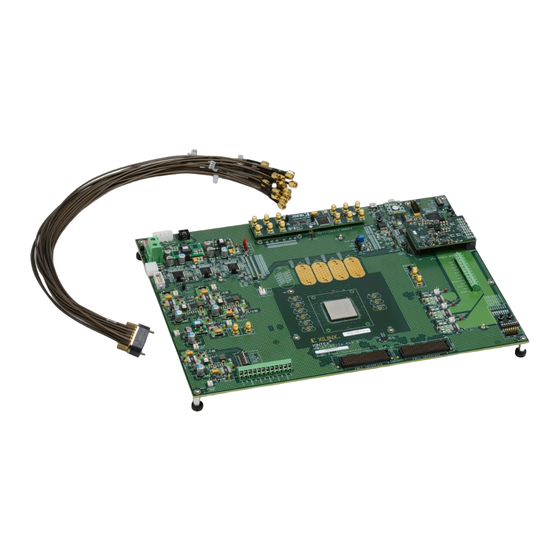
GTX transceiver Quads 115, 116, 117, and 118 on the KC724 board. Note: Figure 1-1 is for reference only and might not reflect the current revision of the board. KC724 IBERT Getting Started Guide www.xilinx.com UG931 (v1.0) October 23, 2012... - Page 8 Chapter 1: KC724 IBERT Getting Started Guide X-Ref Target - Figure 1-1 QUAD_116 QUAD_117 QUAD_115 QUAD_118 UG931_c1_01_080812 Figure 1-1: GTX Quad Locations www.xilinx.com KC724 IBERT Getting Started Guide UG931 (v1.0) October 23, 2012...
- Page 9 For the GTX IBERT demonstration, the output clock frequencies are preset to 125.000 MHz. For more information regarding the SuperClock-2 module, refer to UG770, HW-CLK-101-SCLK2 SuperClock-2 Module User Guide. KC724 IBERT Getting Started Guide www.xilinx.com UG931 (v1.0) October 23, 2012...
-
Page 10: Attach The Gtx Quad Connector
Chapter 1: KC724 IBERT Getting Started Guide Attach the GTX Quad Connector Before connecting the BullsEye cable assembly to the board, firmly secure the blue elastomer seal provided with the cable assembly to the bottom of the connector housing if... -
Page 11: Gtx Tx/Rx Loopback Connections
X-Ref Target - Figure 1-6 UG931_c1_06_080812 Figure 1-6: SMA F-F Adapter X-Ref Target - Figure 1-7 TX Coax SMA F-F Adapter RX Coax UG931_c1_07_080812 Figure 1-7: TX-To-RX Loopback Connection Example KC724 IBERT Getting Started Guide www.xilinx.com UG931 (v1.0) October 23, 2012... -
Page 12: Configuring The Fpga
Chapter 1: KC724 IBERT Getting Started Guide Figure 1-8 shows the KC724 board with the cable connections required for the Quad 115 GTX IBERT demonstration. X-Ref Target - Figure 1-8 CKOUT1_N CKOUT1_P QUAD_115 TX/RX Loopback Connections UG931_c1_08_080912 Figure 1-8: Cable Connections for Quad 115 GTX IBERT Demonstration... - Page 13 GTX Quad 115 GTX Quad 116 GTX Quad 117 GTX Quad 118 LED Scroll DIP Switches Push Buttons USB/UART Place the main power switch SW1 to the ON position. KC724 IBERT Getting Started Guide www.xilinx.com UG931 (v1.0) October 23, 2012...
-
Page 14: Setting Up The Chipscope Pro Software
Chapter 1: KC724 IBERT Getting Started Guide Setting Up the ChipScope Pro Software Start Vivado design suite on the host computer and click Open Project icon (highlighted in Figure 1-10). X-Ref Target - Figure 1-10 UG931_c1_10_100412 Figure 1-10: Vivado Design Suite, Getting Started Page www.xilinx.com... - Page 15 In the Open Project window (Figure 1-11), navigate to the project_1 directory created when Extracting the Project Files. Select project_1.xpr and click OK. X-Ref Target - Figure 1-11 UG931_c1_11_100412 Figure 1-11: Open Project KC724 IBERT Getting Started Guide www.xilinx.com UG931 (v1.0) October 23, 2012...
- Page 16 Chapter 1: KC724 IBERT Getting Started Guide Launch the ChipScope Pro Analyzer tool. From the menu bar, click Flow→ Launch (Figure 1-12). ChipScope Analyzer X-Ref Target - Figure 1-12 UG931_c1_12_100412 Figure 1-12: Launch Chipscope Analyzer In the ChipScope Pro analyzer tool click File → Open Project.
-
Page 17: Starting The Superclock-2 Module
1) An always-on Si570 crystal oscillator and, 2) an Si5368 jitter-attenuating clock multiplier. Outputs from either device can be used to drive the transceiver reference clocks. To start the SuperClock-2 Module: KC724 IBERT Getting Started Guide www.xilinx.com UG931 (v1.0) October 23, 2012... - Page 18 Chapter 1: KC724 IBERT Getting Started Guide In the Project Panel, click VIO Console below UNIT 1: SCLK2 Control (VIO) (Figure 1-15). X-Ref Target - Figure 1-15 UG931_c1_15_080812 Figure 1-15: Project Panel - VIO Console (GTX) The clock sources on the SuperClock-2 module are controlled from the VIO Console.
-
Page 19: Viewing Gtx Transceiver Operation
The line rate for all four GTX transceivers is 12.5 Gbps (see MGT Link Status in Figure 1-18). • The GTX transmitter differential output swing is preset to 850 mV. • Verify that there are no bit errors. KC724 IBERT Getting Started Guide www.xilinx.com UG931 (v1.0) October 23, 2012... -
Page 20: In Case Of Rx Bit Errors
Chapter 1: KC724 IBERT Getting Started Guide X-Ref Target - Figure 1-18 ug931_c1_18_080912 Figure 1-18: GTX IBERT Console In Case of RX Bit Errors If the RX Bit Error Count for any transceiver displays a non-zero value, or to simply reset... -
Page 21: Closing The Ibert Demonstration
Additional information on the ChipScope Pro software and IBERT core can be found in: • UG029, ChipScope Pro Software Cores. • DS855, ChipScope Integrated Bit Error Ratio Test (IBERT) for Kintex-7 GTX (v2.00.a) KC724 IBERT Getting Started Guide www.xilinx.com UG931 (v1.0) October 23, 2012... -
Page 22: Superclock-2 Frequency Table
Chapter 1: KC724 IBERT Getting Started Guide SuperClock-2 Frequency Table Table 1-2 lists the addresses for the frequencies that are programmed into the SuperClock-2 read-only-memory (ROM). Table 1-2: Si570 and Si5368 Frequency Table Frequency Frequency Frequency Address Protocol Address Protocol... - Page 23 465.000 Generic 340.000 Generic 405.000 Generic 470.000 Generic 345.000 Generic 410.000 Generic 475.000 Generic 350.000 Generic 415.000 Generic 480.000 Generic 355.000 Generic 420.000 Generic 485.000 Generic 360.000 Generic 425.000 KC724 IBERT Getting Started Guide www.xilinx.com UG931 (v1.0) October 23, 2012...
-
Page 24: Creating The Gtx Ibert Core
Chapter 1: KC724 IBERT Getting Started Guide Creating the GTX IBERT Core Vivado Design Suite is required to rebuild the designs shown here. This section provides a procedure to create a single Quad GTX IBERT core with integrated SuperClock-2 controller. The procedure assumes Quad 115 and 12.5 Gb/s line rate, but cores for any of the GTX Quads with any supported line rate can be created following the same series of steps. - Page 25 Creating the GTX IBERT Core X-Ref Target - Figure 1-22CORE Generator UG931_c1_22_101512 Figure 1-22: Project Name and Location Fields KC724 IBERT Getting Started Guide www.xilinx.com UG931 (v1.0) October 23, 2012...
- Page 26 Chapter 1: KC724 IBERT Getting Started Guide In the Project Type window, verify RTL Project (the default) is selected. Click Next (Figure 1-23). X-Ref Target - Figure 1-23CORE Generator UG931_c1_23_101512 Figure 1-23: RTL Project For each of the next three windows (Add Sources, Add Existing IP, and Add Constraints) click Next.
- Page 27 In the Default Part window, adjust the filter as shown in Figure 1-24 to select the xc7k325tffg00900-3 device , then click Next. X-Ref Target - Figure 1-24 UG931_c1_24_101512 Figure 1-24: Part Selection KC724 IBERT Getting Started Guide www.xilinx.com UG931 (v1.0) October 23, 2012...
- Page 28 Chapter 1: KC724 IBERT Getting Started Guide Review the New Project Summary window and click Finish (Figure 1-25). X-Ref Target - Figure 1-25 UG931_c1_25_101512 Figure 1-25: New Project Summary www.xilinx.com KC724 IBERT Getting Started Guide UG931 (v1.0) October 23, 2012...
- Page 29 Creating the GTX IBERT Core Click IP Catalog under the Project Manager tab (Figure 1-26). X-Ref Target - Figure 1-26 UG931_c1_26_101512 Figure 1-26: IP Catalog Icon KC724 IBERT Getting Started Guide www.xilinx.com UG931 (v1.0) October 23, 2012...
- Page 30 Chapter 1: KC724 IBERT Getting Started Guide 10. In the IP Catalog pane of the Project Manager window (Figure 1-27) select: Debug & Verification → Debug → IBERT 7 Series GTX (ChipScope Pro - IBERT) 2.02.a Double-click the selected core to begin customization.
- Page 31 Then uncheck the Generate Bitstream using ISE tools box as shown in Figure 1-28 and click Next. X-Ref Target - Figure 1-28 UG931_c1_28_101512 Figure 1-28: IP Customization Window, Page 1 KC724 IBERT Getting Started Guide www.xilinx.com UG931 (v1.0) October 23, 2012...
- Page 32 Chapter 1: KC724 IBERT Getting Started Guide 12. Enter the information shown here and in Figure 1-29, then click Next: • No. of Quads: 1 • Select Quad: QUAD 115 • Max Rate (Gbps): 12.5 • Refclk (MHz): 125.000 •...
- Page 33 MGT1_115: CUSTOM1 / 12.5 Gbps • MGT2_115: CUSTOM1 / 12.5 Gbps • MGT3_115: CUSTOM1 / 12.5 Gbps X-Ref Target - Figure 1-30 UG931_c1_30_101512 Figure 1-30: IP Customization Window, Page 3 KC724 IBERT Getting Started Guide www.xilinx.com UG931 (v1.0) October 23, 2012...
- Page 34 Chapter 1: KC724 IBERT Getting Started Guide 14. Enter the information shown here and in Figure 1-31, then click Next: • MGT0_115: MGTREFCLK1 115 • MGT1_115: MGTREFCLK1 115 • MGT2_115: MGTREFCLK1 115 • MGT3_115: MGTREFCLK1 115 X-Ref Target - Figure 1-31...
- Page 35 1-32, then click Generate. The Customize IP status bar will appear on screen for a few seconds. X-Ref Target - Figure 1-32 UG931_c1_32_100812 Figure 1-32: IP Customization Window, Page 5 KC724 IBERT Getting Started Guide www.xilinx.com UG931 (v1.0) October 23, 2012...
- Page 36 Chapter 1: KC724 IBERT Getting Started Guide 16. When the Customize IP status bar no longer appears on screen, select the XCO file under Design Sources within the Sources pane of the Project Manager window, right-click the XCO file and select Generate Output Products (Figure 1-33).
- Page 37 Creating the GTX IBERT Core X-Ref Target - Figure 1-34 UG931_c1_34_100812 Figure 1-34: Manage Outputs KC724 IBERT Getting Started Guide www.xilinx.com UG931 (v1.0) October 23, 2012...
- Page 38 Chapter 1: KC724 IBERT Getting Started Guide 18. Target generation will take several minutes. After the status bar disappears, change to the implement directory by entering this command in the Tcl Console (Figure 1-35): cd C:/vivado_work/project_1/project_1.srcs/sources_1/ip/chipsco pe_ibert_7series_gtx_v2_02_a_0/ibert_k7_q115/implement/ Note: The parent project directory location in this example is C:/vivado_work (the parent...
- Page 39 19. To take the project through the rest of the RDS and RDI implementation flow to generate a bitstream, enter: source ./v_rdi_implement.tcl (Figure 1-36). X-Ref Target - Figure 1-36 UG931_c1_36_100812 Figure 1-36: Tcl Console, Source Command Entry KC724 IBERT Getting Started Guide www.xilinx.com UG931 (v1.0) October 23, 2012...
- Page 40 Chapter 1: KC724 IBERT Getting Started Guide 20. When the Bitstream Generation Completed dialog window appears, click Cancel (Figure 1-37). X-Ref Target - Figure 1-37 UG931_c1_37_100812 Figure 1-37: Bitstream Generation Complete Window 21. When the Synthesis Completed dialog window appears, click Cancel (Figure 1-38).
- Page 41 23. When the exit confirmation window appears, click OK (Figure 1-40). X-Ref Target - Figure 1-40 UG931_c1_40_100812 Figure 1-40: Close Confirmation 24. Navigate to the C:/vivado_work/project_1/project_1.runs/impl_1 directory to locate the resultant bitstream. KC724 IBERT Getting Started Guide www.xilinx.com UG931 (v1.0) October 23, 2012...
- Page 42 Chapter 1: KC724 IBERT Getting Started Guide www.xilinx.com KC724 IBERT Getting Started Guide UG931 (v1.0) October 23, 2012...
- Page 43 For any breach by Xilinx of this limited warranty, the exclusive remedy of Customer and the sole liability of Xilinx shall be, at the option of Xilinx, to replace or repair the affected products, or to refund to Customer the price of the affected products. The availability of replacement products is subject to product discontinuation policies at Xilinx.
- Page 44 Appendix A: Warranty www.xilinx.com KC724 IBERT Getting Started Guide UG931 (v1.0) October 23, 2012...
Need help?
Do you have a question about the KC724 IBERT and is the answer not in the manual?
Questions and answers